

Page 1

FREESPEAK
DIGITAL WIRELESS
INSTRUCTION MANUAL
Version 2.0.2
Page 2

FreeSpeak Instruction Manual
© 2007, 2008, 2009 Vitec Group Communications Ltd. All rights reserved.
Part Number 810340Z Rev. 8
Vitec Group Communications LLC
850 Marina Village Parkway
Alameda, CA 94501
U.S.A
Vitec Group Communications Ltd
7400 Beach Drive
IQ Cambridge
Cambridgeshire
United Kingdom
CB25 9TP
The Vitec Group plc
Beijing Representative Office
Room 706, Tower B
Derun Building, YongAn Dongli A No.3
Jianwai Ave., Chaoyang District
Beijing, P.R.China 100022
® Clear-Com, CellCom/FreeSpeak and the Clear-Com Communication Systems logo are
registered trademarks of The Vitec Group plc
Website: www.clearcom.com
Page 3

Vitec Group Communications
SOFTWARE LICENSE
IMPORTANT: CAREFULLY READ THE FOLLOWING BEFORE
USING THIS SOFTWARE. USING THE SOFTWARE INDICATES
YOUR ACKNOWLEDGMENT THAT YOU HAVE READ THE
FOLLOWING AND AGREE TO ITS TERMS.
IF YOU DO NOT AGREE, RETURN THE SOFTWARE COMPLETE
TO VITEC GROUP COMMUNICATIONS LIMITED OR CANCEL THE
INSTALLATION.
THIS IS YOUR PROOF THAT YOU HAVE A VALID LICENSE.
PLEASE TREAT IT AS VALUABLE PROPERTY.
VITEC GROUP COMMUNICATIONS LIMITED OR VITEC GROUP
COMMUNICA TIONS, INC., as the case may be (hereinaf ter referred
to as “VGC
computer program and files (the “SOFTWARE
grant to you a non-exclusive and non-transferable License to use
the Software on the following terms. Any new revision or update
of the Software provided by VGC to Customer under this License
shall be governed by the terms and conditions of this License.
”), offers you this storage media containing a
”) and offers to
1. APPLICATION
a. These terms supersede all prior agreements representations
and understandings between you the Customer and VGC and their
authorised representatives relating to the subject matter hereof
, the Software) but shall otherwise be subject to Vitec Group
(i.e.
Communications Terms and Conditions, as amended from time to
time. For the avoidance of doubt, in the event of conflict, these
terms shall prevail.
b. No variation to these terms, nor any other terms or conditions
proposed by you, shall be of any effect unless recorded in a written
document signed by VGC. You confirm that any statement made to
the contrary by you or on your behalf shall not apply to this
License.
c. You confirm that you are not relying on any statement made by
or on behalf of VGC, other than statements recorded in a written
document signed by VGC.
d. VGC and its licensors reserve all rights not expressly granted to
you. VGC's licensors are intended third party beneficiaries of this
Agreement and have the express right to rely upon and directly
enforce the terms set forth herein.
e. You agree that the Software belongs to VGC and its licensors.
You agree that you neither own nor hereby acquire any claim or
right of ownership to the Software or to any related patents,
Clear-Com Communication Systems
FreeSpeak V2,0 Instruction Manual
i
Page 4

copyrights, trademarks or other intellectual property. VGC and its
licensors retain all right, title and interest in and to the Software and
all copies thereof at all times, regardless of the form or media in or
on which the original or other copies may subsequently exist. This
license is not a sale of the original or any subsequent copy.
2. COPYRIGHT
a. The copyright and all other rights in the Software produced by
VGC shall remain with VGC or its suppliers. You must reproduce
any copyright or other notice marked on the Software on any
copies that you make.
3. YOU MAY:
a. Use the Software only at a single site location. If you wish to use
the Software at more than one site you must contact VGC and if
required purchase further Licenses;
b. Make one copy of the Software for archival or back-up purposes,
and;
c. Transfer the Software to an end user of a VGC product, only if
you have made it clear to VGC that you are not the end user and
you assign all of your rights under this License and make no use of
the Software yourself.
4. YOU MAY NOT:
a. Use the Software or make copies of it except as permitted in this
License;
b. Publish or distribute the computer images, sound files or fonts
included with the Software as computer images, sound files or
fonts;
c. Translate, reverse engineer, decompile or disassemble the
Software, except to the extent the foregoing restriction is exp ressly
prohibited by applicable law;
d. Rent, lease, assign or transfer the Software except as set out
above; or
e. Modify the Software or merge all or any part of the Software in
another program.
5. TERM:
a. This License shall continue for as long as you use the Software.
However, it will terminate if you fail to comply with any of its terms
or conditions. You agree, upon termination, to destroy all copies of
the Software. The Limitations of Warranties and Liability set out
below shall continue in force even after any termination.
6. LIMITED WARRANTY:
a. VGC warrants that the storage media in this Software will be free
from defects in materials and workmanship for 90 days from the
date you acquire it. If such a defect occurs, return it to us at the
address below and we will replace it free. This remedy is your
exclusive remedy for breach of this warranty.
ii
Clear-Com Communication Systems
FreeSpeak V2,0 Instruction Manual
Page 5

b. After the initial 90 days, THE SOFTWARE IS PROVIDED "AS
IS" WITHOUT WARRANTY OF ANY KIND EITHER EXPRESS,
IMPLIED OR STATUTORY, INCLUDING BUT NOT LIMITED TO
THE IMPLIED WARRANTIES OF MERCHANTABILITY, FITNESS
FOR A P ARTICULAR PURPOSE, PERFORMANCE, ACCURACY,
RELIABILITY, OR NON-INFRINGEMENT OF THIRD-PARTY
INTELLECTUAL PROPERTY RIGHTS. This constitutes an
essential part of this Lic ense.
7. LIMITATION OF LIABILITY:
a. For the avoidance of doubt, all conditions imposed by law
covering matters such as fitness for purpose, compliance to
description, negligence and quality are expressly excluded
from this agreement and you agree to accept the foregoing
warranty in lieu of all such items.
b. IN NO EVENT SHALL VGC BE LIABLE FOR ANY LOSS OF
PROFITS, LOSS OF BUSINESS, LOSS OF DATA OR USE OF
DATA, INTERRUPTION OF BUSINESS, OR FOR INDIRECT,
SPECIAL, INCIDENT AL, EXEMPLARY, MUL TIPLE, PUNITIVE OR
CONSEQUENTIAL DAMAGES OF ANY KIND, WHETHER
BASED ON CONTRACT, TORT (INCLUDING WITHOUT
LIMITATION, NEGLIGENCE), WARRANTY, GUARANTEE OR
ANY OTHER LEGAL OR EQUITABLE GROUNDS, EVEN IF VGC
HAS BEEN ADVISED OF THE POSSIBILITY OF SUCH
DAMAGES.
c. The warranty is personal to you (or end user if you have made it
clear that you are not the end user) and may not be transferred
(except as permitted expressly above).
d. VGC shall not be a liable for failure to perform any obligation to
you where such failure is due to circumstances beyond VGC’s
reasonable control.
e. VGC offers extended warranties and, if you are not satisfied
with the above, you should consider such warranties or
consider separate insurance.
Clear-Com Communication Systems
FreeSpeak V2,0 Instruction Manual
8. RESTRICTED RIGHTS:
If this Software is acquired by or for the U.S. Government then it is provided with Restricted Rights. Use, duplication, or disclosure by the U.S.
Government is subject to restrictions as set forth in subparagraph
(c)(1)(ii) of The Rights in Technical Data and Computer Software clause
at DFARS 252.227-7013, or subparagraphs (c)(1) and (2) of the Commercial Computer Software - Restricted Rights at 48 CFR 52.227-19, or
clause 18-52.227-86(d) of the NASA Supplement to the FAR, as applicable. Contractor/manufacturer: Vitec Group Communications Limited,
7400 Beach Drive, Cambridge, England CB25 9TP or Vitec Group
Communications, LLC., 850 Marina Village Parkway, Alameda, CA
94501.
9. OTHER ISSUES:
a. Any failure by VGC to insist on its strict rights under this
Agreement shall not be deemed to be a waiver of those (or any
iii
Page 6

other rights) and only a duly executed written release shall
constitute such a waiver.
b. If any of these conditions is deemed invalid or unenforce able the
remainder shall be unaffected.
c. VGC's dealings with you shall be governed by English law if you
are resident in the EMEA region and California law if you are
resident elsewhere. The federal and state courts of California for
Non-EMEA Customers and English Courts for EMEA Customers
shall have exclusive jurisdiction to adjudicate any dispute arising
out of this Agreement.
d. If any document is written in more than one language the
English text shall prevail.
e. Capitalized terms not defined herein shall have the meanings
set forth in Vitec Group Communications' Terms and Conditions, as
amended from time to time.
iv
Clear-Com Communication Systems
FreeSpeak V2,0 Instruction Manual
Page 7

CONTENTS
GETTING STARTED: AN INTRODUCTION TO
FREESPEAK . . . . . . . . . . . . . . . . . . . . . . . . . . . . . . 1-1
FreeSpeak Features. . . . . . . . . . . . . . . . . . . . . . . . . . . . . . . . . . . . .1-2
A FreeSpeak Communication System . . . . . . . . . . . . . . . . . . . . . . .1-3
Important Installation Information . . . . . . . . . . . . . . . . . . . . . . . . .1-5
System Password . . . . . . . . . . . . . . . . . . . . . . . . . . . . . . . . . . .1-5
Default Map . . . . . . . . . . . . . . . . . . . . . . . . . . . . . . . . . . . . . . . .1-5
QUICK START. . . . . . . . . . . . . . . . . . . . . . . . . . . . . 2-1
Creating a Wireless Party Line. . . . . . . . . . . . . . . . . . . . . . . . . . . . .2-8
Assigning the Wireless Party Line Label to FreeSpeak Beltpack Keys
2-8
Calling the Wireless Party Line from the Beltpacks . . . . . . . . . . . . .2-9
Calling the Wireless Party Line from the 4-Wire Audio Device. . . .2-10
Calling the Wireless Party Line from the Wired Party-Line Beltpack . .
2-11
OPERATING THE FREESPEAK BASESTATION. . 3-1
Introduction. . . . . . . . . . . . . . . . . . . . . . . . . . . . . . . . . . . . . . . . . . . .3-1
Understanding Front-Panel Operation . . . . . . . . . . . . . . . . . . . . . . .3-2
Headset Connector . . . . . . . . . . . . . . . . . . . . . . . . . . . . . . . . . .3-2
& Channel A Talk Switch and Light/Listen Level Knob . . . . . .3-2
A/B Reply Button . . . . . . . . . . . . . . . . . . . . . . . . . . . . . . . . . . . .3-3
& Channel B Talk Switch and Light/Listen Level Knob . . . . . .3-3
Party Line Channels A and B Enable Switches. . . . . . . . . . . . .3-3
Program Audio Enable Switch and Light. . . . . . . . . . . . . . . . . .3-3
Antenna Light Display . . . . . . . . . . . . . . . . . . . . . . . . . . . . . . . .3-3
Display Screen. . . . . . . . . . . . . . . . . . . . . . . . . . . . . . . . . . . . . .3-4
Setup/Enter Knob . . . . . . . . . . . . . . . . . . . . . . . . . . . . . . . . . . .3-4
Power Switch. . . . . . . . . . . . . . . . . . . . . . . . . . . . . . . . . . . . . . .3-4
CONNECTING THE FREESPEAK BASESTATION 4-1
Understanding the Back-Panel Connectors . . . . . . . . . . . . . . . . . . .4-1
IEC Power Connector. . . . . . . . . . . . . . . . . . . . . . . . . . . . . . . .4-2
Party Line Channel A Connectors . . . . . . . . . . . . . . . . . . . . . . .4-2
Party Line Channel B Connectors . . . . . . . . . . . . . . . . . . . . . . .4-2
Program Input Connector . . . . . . . . . . . . . . . . . . . . . . . . . . . . .4-2
Clear-Com Communication Systems
FreeSpeak V2.0 Instruction Manual
i
Page 8

Stage Announce Output Connector. . . . . . . . . . . . . . . . . . . . . .4-2
Stage Announce Relay . . . . . . . . . . . . . . . . . . . . . . . . . . . . . . .4-3
4-Wire Matrix Ports . . . . . . . . . . . . . . . . . . . . . . . . . . . . . . . . . .4-3
Base Loop Connector (not used). . . . . . . . . . . . . . . . . . . . . . . .4-3
LAN Connector . . . . . . . . . . . . . . . . . . . . . . . . . . . . . . . . . . . . .4-3
PC Connector . . . . . . . . . . . . . . . . . . . . . . . . . . . . . . . . . . . . . .4-3
Transceiver Connectors. . . . . . . . . . . . . . . . . . . . . . . . . . . . . . .4-3
Connecting to Party-Line Intercom Systems . . . . . . . . . . . . . . . . . .4-4
Clear-Com and Compatible Party-Line. . . . . . . . . . . . . . . . . . . . .4-4
Connecting Directly to Clear-Com Party-Line Beltpacks. . . . . . . .4-5
Connecting to an RTS™ Wired Beltpack . . . . . . . . . . . . . . . . . . .4-6
Front-Panel Adjustments for Party-Line Connections. . . . . . . . . .4-6
Troubleshooting Party-Line Connections . . . . . . . . . . . . . . . . . . .4-8
Reducing FreeSpeak Beltpack echo when talking to a analogue
party-line. . . . . . . . . . . . . . . . . . . . . . . . . . . . . . . . . . . . . . . . . . . . . .4-8
How to set the microphone gain in the beltpack. . . . . . . . . .4-8
Include the Party-Line channel inside a Wireless Party-Line
group. . . . . . . . . . . . . . . . . . . . . . . . . . . . . . . . . . . . . . . . . . . . . . . . .4-8
How to set the VOX gating level on the Party-Line connected to
the Basestation. . . . . . . . . . . . . . . . . . . . . . . . . . . . . . . . . . . . . . . . .4-8
Auto null the Party-Line channel at the Basestation. . . . . . .4-9
Wireless Party Line. . . . . . . . . . . . . . . . . . . . . . . . . . . . . . . . . . . . .4-10
Connecting to 4-Wire and Digital Matrix Intercom . . . . . . . . . . . . .4-10
Connecting with Clear-Com Matrix Plus . . . . . . . . . . . . . . . . . . .4-12
Connecting with Clear-Com Eclipse Digital Matrix . . . . . . . . . . .4-12
Connecting with Other Digital Matrix Intercom Systems. . . . . . .4-13
Connecting with Other 4-Wire Devices. . . . . . . . . . . . . . . . . . . .4-14
Connecting to a Program Audio Source. . . . . . . . . . . . . . . . . . . . .4-14
IFB Configuration . . . . . . . . . . . . . . . . . . . . . . . . . . . . . . . . . . . . . .4-15
Connecting to the Stage Announce Output . . . . . . . . . . . . . . . . . .4-16
Connecting to a PC. . . . . . . . . . . . . . . . . . . . . . . . . . . . . . . . . . . . .4-17
Connecting Via the Serial Port . . . . . . . . . . . . . . . . . . . . . . . . . .4-17
Connecting Via the LAN Port . . . . . . . . . . . . . . . . . . . . . . . . . . .4-18
Connecting to Transceiver/Antennas (FS-TA) . . . . . . . . . . . . . . . .4-18
Connecting One Transceiver/Antenna (FS-TA) Directly to A Trans-
ceiver Port. . . . . . . . . . . . . . . . . . . . . . . . . . . . . . . . . . . . . . . . . . . .4-18
Connecting Transceiver/Antennas with a Splitter (PD2203) . . . .4 -19
Powering an Antenna or Antenna Splitter . . . . . . . . . . . . . . . . . .4-20
PROGRAMMING A SYSTEM FROM THE BASESTA-
TION . . . . . . . . . . . . . . . . . . . . . . . . . . . . . . . . . . . . 5-1
A Note About Terminology . . . . . . . . . . . . . . . . . . . . . . . . . . . . . . . .5-2
ii
Clear-Com Communication Systems
FreeSpeak V2.0 Instruction Manual
Page 9

Using the Basestation’s Programming Menus . . . . . . . . . . . . . . . . .5-2
Saving Changes . . . . . . . . . . . . . . . . . . . . . . . . . . . . . . . . . . . . . . . .5-2
Basestation Password . . . . . . . . . . . . . . . . . . . . . . . . . . . . . . . . . . .5-2
Changing Beltpack Labels . . . . . . . . . . . . . . . . . . . . . . . . . . . . . . . .5-4
Setting and Changing Port Labels . . . . . . . . . . . . . . . . . . . . . . . . . .5-6
Setting and Changing Group Labels. . . . . . . . . . . . . . . . . . . . . . . . .5-7
Adding Group Members . . . . . . . . . . . . . . . . . . . . . . . . . . . . . . . . .5-10
Beltpacks . . . . . . . . . . . . . . . . . . . . . . . . . . . . . . . . . . . . . . . . . . . . 5-11
Assigning Labels to Beltpacks Keys . . . . . . . . . . . . . . . . . . . . . .5-11
Setting the Beltpack Audio Level. . . . . . . . . . . . . . . . . . . . . . . . .5-14
Setting Beltpack Latching . . . . . . . . . . . . . . . . . . . . . . . . . . . . . .5-14
Setting Beltpack Groups . . . . . . . . . . . . . . . . . . . . . . . . . . . . . . .5-15
Setting Beltpack Labels. . . . . . . . . . . . . . . . . . . . . . . . . . . . . . . .5-16
Registering a Beltpack . . . . . . . . . . . . . . . . . . . . . . . . . . . . . . . .5-16
Setting Input and Output Port Levels . . . . . . . . . . . . . . . . . . . . . . .5-17
Setting Port Call Destination. . . . . . . . . . . . . . . . . . . . . . . . . . . .5-19
Configuring a Party Line. . . . . . . . . . . . . . . . . . . . . . . . . . . . . . . . .5-22
Basestation SYSTEM Menu. . . . . . . . . . . . . . . . . . . . . . . . . . . . . .5-26
System INFO (“INFO”) . . . . . . . . . . . . . . . . . . . . . . . . . . . . . . . .5-27
Restoring the Defaults (“DEFAULT”). . . . . . . . . . . . . . . . . . . . . .5-27
ANTENNAS (“ANTENNAS”) . . . . . . . . . . . . . . . . . . . . . . . . . . . .5-27
Setting the IP Address (“IP”). . . . . . . . . . . . . . . . . . . . . . . . . . . .5-28
Locking Front-Panel Enable Buttons (“Lock”). . . . . . . . . . . . . . .5-29
Remote Microphone Kill (“RMK”) . . . . . . . . . . . . . . . . . . . . . . . .5-29
Kill Beltpack Microphones (“KILL(BP”) . . . . . . . . . . . . . . . . . .5-29
Kill Party Line Microphones (“KILL(PL)”). . . . . . . . . . . . . . . . .5-29
Kill All Microphones (“KILL(ALL)”) . . . . . . . . . . . . . . . . . . . . . .5-30
Battery Indicator (“BATTERY”) . . . . . . . . . . . . . . . . . . . . . . . . . .5-30
Clear-Com Communication Systems
FreeSpeak V2.0 Instruction Manual
OPERATING THE FREESPEAK WIRELESS BELT-
PACK. . . . . . . . . . . . . . . . . . . . . . . . . . . . . . . . . . . . 6-1
Overview of the Wireless Belpack . . . . . . . . . . . . . . . . . . . . . . . . . .6-1
Beltpack Top Control Section . . . . . . . . . . . . . . . . . . . . . . . . . . . .6-2
Talk Knobs, Channels A and B . . . . . . . . . . . . . . . . . . . . . . . . .6-2
Level-Control Lights, Channels A and B . . . . . . . . . . . . . . . . . .6-3
Talk/Listen Lights, Channels A and B . . . . . . . . . . . . . . . . . . . .6-3
Answer-Back Lights. . . . . . . . . . . . . . . . . . . . . . . . . . . . . . . . . .6-3
Combo Button . . . . . . . . . . . . . . . . . . . . . . . . . . . . . . . . . . . . . .6-3
Beltpack Front/Display Section. . . . . . . . . . . . . . . . . . . . . . . . . . .6-4
Backlit LCD Display. . . . . . . . . . . . . . . . . . . . . . . . . . . . . . . . . .6-4
iii
Page 10

Left and Right Scroll Buttons. . . . . . . . . . . . . . . . . . . . . . . . . . .6-4
Enter/Answer-Back Button. . . . . . . . . . . . . . . . . . . . . . . . . . . . .6-4
Beltpack Batteries. . . . . . . . . . . . . . . . . . . . . . . . . . . . . . . . . . . . . . .6-5
Beltpack Rear/Battery Section . . . . . . . . . . . . . . . . . . . . . . . . . . .6-5
Power Button. . . . . . . . . . . . . . . . . . . . . . . . . . . . . . . . . . . . . . .6-5
Battery Case . . . . . . . . . . . . . . . . . . . . . . . . . . . . . . . . . . . . . . .6-5
Belt Clip . . . . . . . . . . . . . . . . . . . . . . . . . . . . . . . . . . . . . . . . . . .6-6
Beltpack Bottom Connector Section . . . . . . . . . . . . . . . . . . . . . . .6-6
Data Connector . . . . . . . . . . . . . . . . . . . . . . . . . . . . . . . . . . . . .6-6
Headset Connector . . . . . . . . . . . . . . . . . . . . . . . . . . . . . . . . . .6-6
Battery Recharger Connector . . . . . . . . . . . . . . . . . . . . . . . . . .6-7
Beltpack Turn-On Sequence. . . . . . . . . . . . . . . . . . . . . . . . . . . . .6-7
Beltpack Turn-Off Sequence. . . . . . . . . . . . . . . . . . . . . . . . . . . . .6-7
Powering the FreeSpeak Beltpack . . . . . . . . . . . . . . . . . . . . . . . .6-7
Registering Beltpacks with the Basestation . . . . . . . . . . . . . . . . .6-9
Removing Registered Beltpacks from the Basestation. . . . . . . .6-10
Accessing the Talk/Listen Paths on the FreeSpeak Beltpack. . . . .6-10
Setting and Adjusting Listen Levels . . . . . . . . . . . . . . . . . . . . . .6-11
Headset Limiter. . . . . . . . . . . . . . . . . . . . . . . . . . . . . . . . . . . . . .6-12
Using the Beltpack Answer-Back Functions . . . . . . . . . . . . . . . .6-12
Beltpack Menu Options. . . . . . . . . . . . . . . . . . . . . . . . . . . . . . . . . .6-13
Alarm Options . . . . . . . . . . . . . . . . . . . . . . . . . . . . . . . . . . . . . . .6-13
Low Battery Alarm . . . . . . . . . . . . . . . . . . . . . . . . . . . . . . . . . .6-13
Low Signal Alarm. . . . . . . . . . . . . . . . . . . . . . . . . . . . . . . . . . .6-13
Audio Options . . . . . . . . . . . . . . . . . . . . . . . . . . . . . . . . . . . . . . .6-14
Headphone-Off Level Option. . . . . . . . . . . . . . . . . . . . . . . . . .6-14
Page Lock Option . . . . . . . . . . . . . . . . . . . . . . . . . . . . . . . . . .6-14
Headphone Limiter Option. . . . . . . . . . . . . . . . . . . . . . . . . . . .6-14
Microphone Type Option . . . . . . . . . . . . . . . . . . . . . . . . . . . . .6-14
Microphone Level Option. . . . . . . . . . . . . . . . . . . . . . . . . . . . .6-15
Headset Options . . . . . . . . . . . . . . . . . . . . . . . . . . . . . . . . . . .6-15
View Status . . . . . . . . . . . . . . . . . . . . . . . . . . . . . . . . . . . . . . . . .6-15
Role Information . . . . . . . . . . . . . . . . . . . . . . . . . . . . . . . . . . .6-15
Beltpack Version . . . . . . . . . . . . . . . . . . . . . . . . . . . . . . . . . . .6-15
Beltpack ID . . . . . . . . . . . . . . . . . . . . . . . . . . . . . . . . . . . . . . .6-15
RF Carrier Mask . . . . . . . . . . . . . . . . . . . . . . . . . . . . . . . . . . .6-15
Connection Info . . . . . . . . . . . . . . . . . . . . . . . . . . . . . . . . . . . .6-16
Adjust Contrast . . . . . . . . . . . . . . . . . . . . . . . . . . . . . . . . . . . .6-16
iv
Clear-Com Communication Systems
FreeSpeak V2.0 Instruction Manual
Page 11

PROGRAMMING AT THE BELTPACK . . . . . . . . . . 7-1
Introduction to Programming on the Beltpack. . . . . . . . . . . . . . . . . .7-1
Beltpack Programming - Menu Structure . . . . . . . . . . . . . . . . . . . . .7-1
Main Programming Menu . . . . . . . . . . . . . . . . . . . . . . . . . . . . . . . . .7-2
The Alarm Options Menu . . . . . . . . . . . . . . . . . . . . . . . . . . . . . . . . .7-3
Switching the Low Battery Alarm ON and OFF. . . . . . . . . . . . . . .7-4
Low Battery Alarm Off . . . . . . . . . . . . . . . . . . . . . . . . . . . . . . . .7-4
Low Battery Alarm On1 . . . . . . . . . . . . . . . . . . . . . . . . . . . . . . .7-4
Low Battery Alarm On2 . . . . . . . . . . . . . . . . . . . . . . . . . . . . . . .7-4
Low Battery Alarm Threshold . . . . . . . . . . . . . . . . . . . . . . . . . .7-5
Low Battery Threshold Setup . . . . . . . . . . . . . . . . . . . . . . . . . .7-5
Switching the Low Signal Strength Alarm ON and OFF . . . . . . . .7-5
The Vibra Call Alert Menu. . . . . . . . . . . . . . . . . . . . . . . . . . . . . . .7-5
The Headphone Menu . . . . . . . . . . . . . . . . . . . . . . . . . . . . . . . . . . .7-6
Headset Noise Gate . . . . . . . . . . . . . . . . . . . . . . . . . . . . . . . . . . .7-9
The Microphone Menu . . . . . . . . . . . . . . . . . . . . . . . . . . . . . . . . . . .7-9
The Status (Information) Menu . . . . . . . . . . . . . . . . . . . . . . . . . . . .7-10
Adjust Contrast. . . . . . . . . . . . . . . . . . . . . . . . . . . . . . . . . . . . . . . .7-13
Set Factory Defaults. . . . . . . . . . . . . . . . . . . . . . . . . . . . . . . . . . . .7-14
Tap Latch . . . . . . . . . . . . . . . . . . . . . . . . . . . . . . . . . . . . . . . . . . . .7-14
Keylock. . . . . . . . . . . . . . . . . . . . . . . . . . . . . . . . . . . . . . . . . . . . . .7-15
PTT Configuration. . . . . . . . . . . . . . . . . . . . . . . . . . . . . . . . . . . . . .7-15
Master Volume Control . . . . . . . . . . . . . . . . . . . . . . . . . . . . . . . . . .7-16
Page Options . . . . . . . . . . . . . . . . . . . . . . . . . . . . . . . . . . . . . . . . .7-16
Page Locking . . . . . . . . . . . . . . . . . . . . . . . . . . . . . . . . . . . . . . .7-17
Clear-Com Communication Systems
FreeSpeak V2.0 Instruction Manual
OPERATING THE FREESPEAK TRANS-
CEIVER/ANTENNA . . . . . . . . . . . . . . . . . . . . . . . . . 8-1
Transceiver/Antenna (FS-TA) . . . . . . . . . . . . . . . . . . . . . . . . . . . . . .8-1
FS-TA Top Panel . . . . . . . . . . . . . . . . . . . . . . . . . . . . . . . . . . . . . .8-1
Omnidirectional Antennas . . . . . . . . . . . . . . . . . . . . . . . . . . . . .8-1
FS-TA Bottom/Control Panel. . . . . . . . . . . . . . . . . . . . . . . . . . . . .8-2
Serial Data Connector . . . . . . . . . . . . . . . . . . . . . . . . . . . . . . . .8-2
Data Signal LED . . . . . . . . . . . . . . . . . . . . . . . . . . . . . . . . . . . .8-2
Matrix Connector . . . . . . . . . . . . . . . . . . . . . . . . . . . . . . . . . . . .8-2
Power LED. . . . . . . . . . . . . . . . . . . . . . . . . . . . . . . . . . . . . . . . .8-3
DC In Power Connector. . . . . . . . . . . . . . . . . . . . . . . . . . . . . . .8-3
Cabling the FS-TA Transceiver/Antennas. . . . . . . . . . . . . . . . . . .8-3
Beltpack Support Capacities for Transceiver/Antennas . . . . . . . .8-3
Coverage Areas Under Various Conditions. . . . . . . . . . . . . . . . . .8-4
v
Page 12

Transceiver/Antenna Setup Rules and Tips . . . . . . . . . . . . . . . . .8-4
Transceiver/Antenna Splitter (PD2203) . . . . . . . . . . . . . . . . . . . . . .8-5
PD2203 Front Connector Panel . . . . . . . . . . . . . . . . . . . . . . . . . .8-6
Basestation Connection Indicator Light. . . . . . . . . . . . . . . . . . .8-6
Matrix (FreeSpeak Basestation) Connector. . . . . . . . . . . . . . . .8-6
Splitter-to-Transceiver/Antenna Signal Indicator Light . . . . . . .8-6
Transceiver/Antenna Connectors . . . . . . . . . . . . . . . . . . . . . . .8-6
PD2203 Rear Panel . . . . . . . . . . . . . . . . . . . . . . . . . . . . . . . . . . .8-7
Serial Data Connector . . . . . . . . . . . . . . . . . . . . . . . . . . . . . . . .8-7
Power Indicator . . . . . . . . . . . . . . . . . . . . . . . . . . . . . . . . . . . . .8-7
DC IN Power Connector . . . . . . . . . . . . . . . . . . . . . . . . . . . . . .8-7
EXP IN Connector . . . . . . . . . . . . . . . . . . . . . . . . . . . . . . . . . . .8-7
EXP OUT Connector . . . . . . . . . . . . . . . . . . . . . . . . . . . . . . . . .8-7
Connecting an Antenna Split ter to the FreeS peak Basestat ion and to
Transceiver/Antennas. . . . . . . . . . . . . . . . . . . . . . . . . . . . . . . . . . . .8-8
INSTALLING A SYSTEM. . . . . . . . . . . . . . . . . . . . . 9-1
Placing the Basestation . . . . . . . . . . . . . . . . . . . . . . . . . . . . . . . . . .9-1
Placing the Antennas and Splitters. . . . . . . . . . . . . . . . . . . . . . . . . .9-1
Wiring the Antennas and Splitters. . . . . . . . . . . . . . . . . . . . . . . . .9-2
Determining Coverage Areas . . . . . . . . . . . . . . . . . . . . . . . . . . . .9-2
Doing a Site Survey to Determine Coverage Areas . . . . . . . . . . . . .9-3
Testing Coverage Areas of Individual Antennas . . . . . . . . . . . . . .9-3
Testing Antenna Handoff. . . . . . . . . . . . . . . . . . . . . . . . . . . . . . . .9-5
Getting Information on Active Antenna Status . . . . . . . . . . . . . . .9-6
Assigning Beltpacks to Coverage Areas. . . . . . . . . . . . . . . . . . . .9-7
Conditions Affecting Coverage Areas. . . . . . . . . . . . . . . . . . . . . .9-7
FREESPEAK CONFIGURATION EDITOR . . . . . . 10-1
Introduction . . . . . . . . . . . . . . . . . . . . . . . . . . . . . . . . . . . . . . . . . .10-1
Loading and Saving Configurations . . . . . . . . . . . . . . . . . . . . . . . .10-1
Loading a configuration from disk. . . . . . . . . . . . . . . . . . . . . . . .10-2
COM port selection . . . . . . . . . . . . . . . . . . . . . . . . . . . . . . . . . . .10-2
IP Setup . . . . . . . . . . . . . . . . . . . . . . . . . . . . . . . . . . . . . . . . . . .10-2
Retrieving a configuration from a Freespeak basestation via the
Serial Link. . . . . . . . . . . . . . . . . . . . . . . . . . . . . . . . . . . . . . . . . . . .10-2
Retrieving a configuration from a Freespeak basestation via Ether-
net. . . . . . . . . . . . . . . . . . . . . . . . . . . . . . . . . . . . . . . . . . . . . . . . . .10-4
Help . . . . . . . . . . . . . . . . . . . . . . . . . . . . . . . . . . . . . . . . . . . . .10-5
Clear Map . . . . . . . . . . . . . . . . . . . . . . . . . . . . . . . . . . . . . . . .10-5
Send File . . . . . . . . . . . . . . . . . . . . . . . . . . . . . . . . . . . . . . . . .10-5
vi
Clear-Com Communication Systems
FreeSpeak V2.0 Instruction Manual
Page 13

Exit. . . . . . . . . . . . . . . . . . . . . . . . . . . . . . . . . . . . . . . . . . . . . .10-5
Uploading configurations Using the Serial Link. . . . . . . . . . . . . .10-6
Uploading configurations Using Ethernet . . . . . . . . . . . . . . . . . .10-6
Beltpacks tab . . . . . . . . . . . . . . . . . . . . . . . . . . . . . . . . . . . . . . . . .10-7
Selecting the beltpack to register or edit. . . . . . . . . . . . . . . . . . .10-7
Registering beltpacks Using the Serial Link . . . . . . . . . . . . . . . .10-8
The Overview button. . . . . . . . . . . . . . . . . . . . . . . . . . . . . . . . . .10-9
The Set Defaults Button . . . . . . . . . . . . . . . . . . . . . . . . . . . . . . .10-9
Read Beltpack Settings. . . . . . . . . . . . . . . . . . . . . . . . . . . . .10-10
Write Beltpack Settings . . . . . . . . . . . . . . . . . . . . . . . . . . . . .10-10
Remember My Default Settings. . . . . . . . . . . . . . . . . . . . . . .10-10
Recall My Default Settings. . . . . . . . . . . . . . . . . . . . . . . . . . .10-10
Recall Factory Defaults . . . . . . . . . . . . . . . . . . . . . . . . . . . . .10-11
Headset Limiter . . . . . . . . . . . . . . . . . . . . . . . . . . . . . . . . . . .10-11
MIC Type. . . . . . . . . . . . . . . . . . . . . . . . . . . . . . . . . . . . . . . .10-11
MIC Gain Level . . . . . . . . . . . . . . . . . . . . . . . . . . . . . . . . . . .10-11
MIC Noisegate Level. . . . . . . . . . . . . . . . . . . . . . . . . . . . . . .10-11
Headphone Off Level. . . . . . . . . . . . . . . . . . . . . . . . . . . . . . .10-11
Sidetone Level. . . . . . . . . . . . . . . . . . . . . . . . . . . . . . . . . . . .10-11
Master Volume. . . . . . . . . . . . . . . . . . . . . . . . . . . . . . . . . . . .10-11
Menu Level . . . . . . . . . . . . . . . . . . . . . . . . . . . . . . . . . . . . . .10-12
Page Change. . . . . . . . . . . . . . . . . . . . . . . . . . . . . . . . . . . . .10-12
Keytap Mode . . . . . . . . . . . . . . . . . . . . . . . . . . . . . . . . . . . . .10-12
RSSI Warning . . . . . . . . . . . . . . . . . . . . . . . . . . . . . . . . . . . .10-12
Low Battery Warning . . . . . . . . . . . . . . . . . . . . . . . . . . . . . . .10-12
Keylock . . . . . . . . . . . . . . . . . . . . . . . . . . . . . . . . . . . . . . . . .10-13
Call Alert . . . . . . . . . . . . . . . . . . . . . . . . . . . . . . . . . . . . . . . .10-13
Assigning beltpack keys . . . . . . . . . . . . . . . . . . . . . . . . . . . . . .10-13
The Reply key. . . . . . . . . . . . . . . . . . . . . . . . . . . . . . . . . . . . . .10-14
Key assignment types. . . . . . . . . . . . . . . . . . . . . . . . . . . . . . . .10-15
Latching keys. . . . . . . . . . . . . . . . . . . . . . . . . . . . . . . . . . . . .10-15
On Page Change Cut . . . . . . . . . . . . . . . . . . . . . . . . . . . . . .10-16
Menu . . . . . . . . . . . . . . . . . . . . . . . . . . . . . . . . . . . . . . . . . . .10-16
Advanced Menu Setting . . . . . . . . . . . . . . . . . . . . . . . . . .10-16
Normal Menu Setting . . . . . . . . . . . . . . . . . . . . . . . . . . . .10-16
Basic Menu Setting. . . . . . . . . . . . . . . . . . . . . . . . . . . . . .10-16
None Menu Setting. . . . . . . . . . . . . . . . . . . . . . . . . . . . . .10-16
Input and output levels . . . . . . . . . . . . . . . . . . . . . . . . . . . . . . .10-16
Ports tab . . . . . . . . . . . . . . . . . . . . . . . . . . . . . . . . . . . . . . . . . . .10-17
Selecting the port to edit . . . . . . . . . . . . . . . . . . . . . . . . . . . . . .10-17
Changing the label of the port. . . . . . . . . . . . . . . . . . . . . . . . . .10-18
Clear-Com Communication Systems
FreeSpeak V2.0 Instruction Manual
vii
Page 14

Type drop-down box . . . . . . . . . . . . . . . . . . . . . . . . . . . . . . . . .10-18
Cross Point assignment drop-down box . . . . . . . . . . . . . . . . . .10-18
Input and output levels . . . . . . . . . . . . . . . . . . . . . . . . . . . . . . .10-19
Groups tab . . . . . . . . . . . . . . . . . . . . . . . . . . . . . . . . . . . . . . . . . .10-20
Selecting the group to edit . . . . . . . . . . . . . . . . . . . . . . . . . . . .10-20
Changing the label of the group . . . . . . . . . . . . . . . . . . . . . . . .10-20
Changing the members of the group. . . . . . . . . . . . . . . . . . . . .10-20
Group Overview . . . . . . . . . . . . . . . . . . . . . . . . . . . . . . . . . . . .10-21
Antennas tab . . . . . . . . . . . . . . . . . . . . . . . . . . . . . . . . . . . . . . . .10-21
IFB Tab . . . . . . . . . . . . . . . . . . . . . . . . . . . . . . . . . . . . . . . . . . . . .10-22
Configuring an IFB . . . . . . . . . . . . . . . . . . . . . . . . . . . . . . . . . .10-22
System Tab. . . . . . . . . . . . . . . . . . . . . . . . . . . . . . . . . . . . . . . . . .10-24
DECT carriers . . . . . . . . . . . . . . . . . . . . . . . . . . . . . . . . . . . . . .10-26
Sys ID . . . . . . . . . . . . . . . . . . . . . . . . . . . . . . . . . . . . . . . . . . . .10-26
System Number . . . . . . . . . . . . . . . . . . . . . . . . . . . . . . . . . . . .10-26
FREESPEAK TOOLKIT . . . . . . . . . . . . . . . . . . . . . 11-1
Introduction . . . . . . . . . . . . . . . . . . . . . . . . . . . . . . . . . . . . . . . . . .11-1
Configuration Editor . . . . . . . . . . . . . . . . . . . . . . . . . . . . . . . . . . 11-1
Basestation Serial Firmware Upgrader . . . . . . . . . . . . . . . . . . .11-1
Beltpack and Antenna Serial Firmware Upgrader. . . . . . . . . . . . 11-1
Diagnostic Program. . . . . . . . . . . . . . . . . . . . . . . . . . . . . . . . . . .11-1
Toolkit Installation . . . . . . . . . . . . . . . . . . . . . . . . . . . . . . . . . . . . . . 11-1
Beltpack Registration . . . . . . . . . . . . . . . . . . . . . . . . . . . . . . . . . . . 11-7
Entering beltpack serial numbers into the basestation . . . . . . . . 11-7
Entering the basestation system ID into the beltpack . . . . . . . . 11-7
Basestation Serial Upgrader . . . . . . . . . . . . . . . . . . . . . . . . . . . . .11-8
Upgrading the basestation firmware . . . . . . . . . . . . . . . . . . . . . .11-8
Beltpack Serial Upgrader . . . . . . . . . . . . . . . . . . . . . . . . . . . . . . . 11-11
Installing the Beltpack Upgader. . . . . . . . . . . . . . . . . . . . . . . . . 11-11
Running the Beltpack Upgrader . . . . . . . . . . . . . . . . . . . . . . . .11-13
Basestation Programming Serial Cable Pinout . . . . . . . . . . . . . . 11-14
Beltpack Programming Serial Cable Pinout . . . . . . . . . . . . . . . . .11-15
viii
SPECIFICATIONS. . . . . . . . . . . . . . . . . . . . . . . . . 12-1
Notice about Specifications. . . . . . . . . . . . . . . . . . . . . . . . . . . . .12-4
Clear-Com Communication Systems
FreeSpeak V2.0 Instruction Manual
Page 15

GLOSSARY. . . . . . . . . . . . . . . . . . . . . . . . . . . . . . 13-1
APPENDIX A: DECT CARRIER FREQUENCY CHART
A-1
APPENDIX B: PROGRAMMING MENUS . . . . . . . . B-1
LIMITED WARRANTY. . . . . . . . . . . . . . . . . . . . . . . W-I
TECHNICAL SUPPORT & REPAIR POLICY. . . . . W-V
TECHNICAL SUPPORT POLICY. . . . . . . . . . . . . . . . . . . . . . . . . . W-v
RETURN MATERIAL AUTHORIZATION POLICY . . . . . . . . . . . . .W-vi
REPAIR POLICY . . . . . . . . . . . . . . . . . . . . . . . . . . . . . . . . . . . . . W-viii
Clear-Com Communication Systems
FreeSpeak V2.0 Instruction Manual
ix
Page 16

x
Clear-Com Communication Systems
FreeSpeak V2.0 Instruction Manual
Page 17

FIGURES
Figure 1-1 A FreeSpeak Antenna, Beltpack, and Basestation ........ 1-1
Figure 1-2 A FreeSpeak Digital Wireless Communication System.. 1-3
Figure 1-3 Configurations for a Studio and Large-Scale Broadcast Fa-
cility.................................................................................................. 1-4
Figure 1-4 Default Map Loaded....................................................... 1-5
Figure 1-5 Beltpack Configuration with the Default Map ................. 1-6
Figure 2-1 Connect the FreeSpeak Basestation to the Wired Devices .
2-2
Figure 2-2 Clear the Basestation’s Memory and Enable the Party Line
2-3
Figure 2-3 Overview of Beltpack Operation..................................... 2-4
Figure 3-1 FreeSpeak Basestation Front Panel .............................. 3-2
Figure 4-1 FreeSpeak Basestation Back Panel............................... 4-1
Figure 4-2 VOX Gating Level on Party Line Connection................. 4-8
Figure 4-3 VOX Gate Setting Examples.......................................... 4-9
Figure 4-4 Wireless Party Line Audio Flow.................................... 4-10
Figure 4-5 Front View of RJ-45 Connector.................................... 4-11
Figure 4-6 IFB Audio Path............................................................. 4-15
Figure 4-7 Powering an Antenna Splitter....................................... 4-21
Figure 5-1 Initial Password Request Display................................... 5-3
Figure 5-2 System Password Menu................................................. 5-3
Figure 5-3 System Password Entry................................................. 5-3
Figure 5-4 From the MAIN menu, select BELTPACKS ................... 5-4
Figure 5-5 Available Beltpacks Menu.............................................. 5-4
Figure 5-6 First Beltpack Programming Options Menu.................... 5-4
Figure 5-7 Second Beltpack Programming Menu............................ 5-5
Figure 5-8 Editing a Beltpack’s Label.............................................. 5-5
Figure 5-9 Select “Ports” from the Main Menu................................. 5-6
Figure 5-10 First Available Ports Menu ........................................... 5-6
Figure 5-11 Second Available Ports Menu...................................... 5-6
Figure 5-12 Port Programming Options Menu................................. 5-6
Figure 5-13 Editing a Port’s Label ................................................... 5-7
Figure 5-14 Standard Group Labels................................................ 5-8
Figure 5-15 Wireless Party Line Group Labels................................ 5-8
Figure 5-16 Select Label from the Menu ......................................... 5-8
Figure 5-17 Group Name Edit Menu................................................ 5-8
Figure 5-18 Group Programming Options Menu ........................... 5-10
Figure 5-19 Adding Members to a Group...................................... 5-10
Figure 5-20 First Beltpack Menu.................................................... 5-11
Figure 5-21 Second Beltpack Menu .............................................. 5-11
Figure 5-22 Assign communication routes (“labels”) to a beltpack key.
5-12
Figure 5-23 Beltpack Display....................................................... 5-12
Figure 5-24 Select the source/destination to assign to that beltpack key
5-13
Figure 5-25 Key Type Menu.......................................................... 5-13
Clear-Com Communication Systems
FreeSpeak V2.0 Instruction Manual
i
Page 18

Figure 5-26 Beltpack Levels Menu................................................ 5-14
Figure 5-27 Beltpack Input Level Setup......................................... 5-14
Figure 5-28 Beltpack Output Level Setup...................................... 5-14
Figure 5-29 Beltpack Latching Menu............................................. 5-15
Figure 5-30 Beltpack Group Editing Menu..................................... 5-15
Figure 5-31 Beltpack Groups Selected.......................................... 5-15
Figure 5-32 Labels Selected on the Beltpack Menu...................... 5-16
Figure 5-33 Beltpack Label Editing Menu...................................... 5-16
Figure 5-34 Beltpack Registration Menu ....................................... 5-17
Figure 5-35 Available Audio Ports Menu....................................... 5-17
Figure 5-36 Selected Port Menu for Level Setting......................... 5-18
Figure 5-37 Port Levels Menu ....................................................... 5-18
Figure 5-38 Port Input Level Setup................................................ 5-18
Figure 5-39 Port Output Level Setup............................................. 5-18
Figure 5-40 Available Audio Ports Menu....................................... 5-19
Figure 5-41 Selected Port Menu for Calls...................................... 5-19
Figure 5-42 Port Call Menu............................................................ 5-19
Figure 5-43 Port Destination Select Menu..................................... 5-20
Figure 5-44 Available Audio Ports Menu....................................... 5-20
Figure 5-45 Selected Port Menu for Calls...................................... 5-20
Figure 5-46 Port Call Menu............................................................ 5-20
Figure 5-47 Port Destination Select Menu..................................... 5-21
Figure 5-48 First Party Line Connection Type Menu..................... 5-22
Figure 5-49 Second Party Line Connection Type Menu................ 5-22
Figure 5-50 Party Line Noisegate Menu........................................ 5-23
Figure 5-51 Party Line Noisegate Options Menu........................... 5-23
Figure 5-52 Party Line Noisegate Trigger Level............................ 5-23
Figure 5-53 VOX Delay Setup....................................................... 5-23
Figure 5-54 Level Editing Menu for Party Line .............................. 5-24
Figure 5-55 Party Line Input Level................................................. 5-24
Figure 5-56 Party Line Output Level.............................................. 5-24
Figure 5-57 Party Line LoNULL Level ........................................... 5-25
Figure 5-58 Party Line HiNULL Level............................................ 5-25
Figure 5-59 System Menu 1 .......................................................... 5-26
Figure 5-60 System Menu 2 .......................................................... 5-26
Figure 5-61 System Menu 3 .......................................................... 5-26
Figure 5-62 System Info Menu ...................................................... 5-27
Figure 5-63 Restore Defaults Menu............................................... 5-27
Figure 5-64 ANTENNAS menu...................................................... 5-27
Figure 5-65 IP Address Menu........................................................ 5-28
Figure 5-66 Lock Enable Menu...................................................... 5-29
Figure 5-67 Remote MIC Kill Menu .............................................. 5-29
Figure 5-68 Battery Level Menu ................................................... 5-30
Figure 6-1 Overview of Beltpack Functions..................................... 6-1
Figure 6-2 View of Top of Beltpack.................................................. 6-2
Figure 6-3 View of Front of Beltpack ............................................... 6-4
Figure 6-4 View of Back of Beltpack................................................ 6-5
Figure 6-5 View of Bottom of Beltpack ............................................ 6-6
Figure 6-6 Battery Discharge Characteristics.................................. 6-8
Figure 6-7 How the beltpack displays its six communication routes......
ii
Clear-Com Communication Systems
FreeSpeak V2.0 Instruction Manual
Page 19

6-10
Figure 7-1 Connection Information Display ................................... 7-12
Figure 8-1 FreeSpeak Transceiver/Antenna.................................... 8-1
Figure 8-2 FreeSpeak Transceiver/Antenna Bottom/Control Panel 8-2
Figure 8-3 FreeSpeak Splitter Front Connector Panel .................... 8-6
Figure 8-4 FreeSpeak Splitter Rear Connector Panel..................... 8-7
Figure 9-1 A Beltpack’s Site Survey Screen.................................... 9-4
Figure 9-2 Mapping overlapping coverage zones............................ 9-5
Figure 9-3 ANTNS menu................................................................. 9-6
Figure 10-1 Configuration Editor Initial Screen.............................. 10-1
Figure 10-2 Map Select Screen..................................................... 10-2
Figure 10-3 Configuration Editor Serial Timeout ........................... 10-3
Figure 10-4 Configuration Setup.................................................... 10-3
Figure 10-5 Map Upload Progress................................................. 10-4
Figure 10-6 Configuration Editor Ethernet Timeout....................... 10-4
Figure 10-7 Configuration Setup.................................................... 10-5
Figure 10-8 Beltpacks Tab............................................................. 10-7
Figure 10-9 Beltpack List............................................................... 10-7
Figure 10-10 Beltpack Label.......................................................... 10-8
Figure 10-11 Registering a Beltpack ............................................. 10-8
Figure 10-12 Beltpack Serial Number............................................ 10-9
Figure 10-13 Beltpack Overview.................................................... 10-9
Figure 10-14 Beltpack Defaults Setup......................................... 10-10
Figure 10-15 Beltpack Page Number .......................................... 10-13
Figure 10-16 Beltpack Key Assignments..................................... 10-14
Figure 10-17 Input and Output Levels......................................... 10-17
Figure 10-18 Ports Tab................................................................ 10-17
Figure 10-19 Party Line Port Type Menu..................................... 10-18
Figure 10-20 Cross Point List for Port ......................................... 10-19
Figure 10-21 Party Line Crosspoint Type.................................... 10-19
Figure 10-22 Groups Tab ............................................................ 10-20
Figure 10-23 Group Overview Display......................................... 10-21
Figure 10-24 Antennas Tab......................................................... 10-21
Figure 10-25 Antenna Cable Length Setup................................. 10-22
Figure 10-26 IFB Configuration Tab............................................ 10-22
Figure 10-27 IFB Selection List ................................................... 10-23
Figure 10-28 Dim Level List......................................................... 10-23
Figure 10-29 System Tab............................................................ 10-24
Figure 10-30 Password Entry...................................................... 10-24
Figure 10-31 Password Entered.................................................. 10-25
Figure 10-32 Country Setup ........................................................ 10-25
Figure 11-1 Previous Version Uninstall ......................................... 11-2
Figure 11-2 Toolkit Install Startup.................................................. 11-3
Figure 11-3 Toolkit Installer Names............................................... 11-3
Figure 11-4 Toolkit Installation Path.............................................. 11-4
Figure 11-5 Toolkit Start Menu Setup............................................ 11-5
Figure 11-6 Toolkit Install Confirm................................................. 11-6
Figure 11-7 Installation Completion Display.................................. 11-6
Figure 11-8 Upgrading Basestation Firmware............................... 11-8
Figure 11-9 Select Firmware File................................................... 11-9
Clear-Com Communication Systems
FreeSpeak V2.0 Instruction Manual
iii
Page 20

Figure 11-10 Firmware Download ................................................. 11-9
Figure 11-11 Download Timeout ................................................. 11-10
Figure 11-12 Beltpack Upgrader Installation Start....................... 11-11
Figure 11-13 Set Installation Directory ........................................ 11-11
Figure 11-14 Beltpack Upgrader Program Group........................ 11-12
Figure 11-15 Installer Version Conflict......................................... 11-12
Figure 11-16 Installation Completed............................................ 11-13
Figure 11-17 Beltpack Upgrader Startup..................................... 11-13
Figure 11-18 Beltpack Upgrade Progress ................................... 11-13
Figure B-1 Programming Menus...................................................... B-1
iv
Clear-Com Communication Systems
FreeSpeak V2.0 Instruction Manual
Page 21

TABLES
Table 4-1 Party Line Pinout............................................................. 4-4
Table 4-2 FreeSpeak Basestation 4-Wire Pinout .......................... 4-12
Table 4-3 Pinouts for Connecting to Other Digital Matrix Intercom Sys-
tems............................................................................................... 4-13
Table 4-4 IFB Key Configurations.................................................. 4-15
Table 4-5 Pin Assignments for Stage Announce Connector ......... 4-16
Table 4-6 Pinout for Cable to Upgrade Basestation Firmware...... 4-17
Table 4-7 Pinout for Cable to Upgrade Beltpack Firmware........... 4-18
Table 7-1 Connection Information ................................................. 7-12
Table 9-1 How antennas are numbered.......................................... 9-6
Table 11-1 Null-Modem Cable Pinout.......................................... 11-14
Table 11-2 Beltpack Programming Serial Cable Pinout .............. 11-15
Table A-1 DECT Carrier Frequency Chart....................................... A-1
Clear-Com Communication Systems
FreeSpeak V2.0 Instruction Manual
i
Page 22

ii
Clear-Com Communication Systems
FreeSpeak V2.0 Instruction Manual
Page 23

IMPORTANT SAFETY INSTRUCTIONS
Please read and follow these instructions before operating a FreeSpeak wireless
communication system. Keep these instructions for future reference.
(1) WARNING: To reduce the risk of fire or electric shock, do not
expose this apparatus to rain or moisture.
(2) Do not use the apparatus near water.
(3) Clean only with a dry cloth.
Please read and follow these
instructions before operating
a FreeSpeak wireless
communication system.
(4) Do not block any ventilation openings. Install in accordance
with the manufacturer’s instructions. Install the FreeSpeak
wireless communication system according to the directions in
the Installation Chapter of this manual.
(5) Do not install near any heat sources such as radiators, heat
registers, stoves, or other apparatus (including amplifiers) that
produce heat. Do not place naked flame sources such as candles
on or near the matrix.
(6) Do not defeat the safety purpose of the polarized plug or
grounding-type plug. A polarized plug has two blades with one
wider than the other . A grounding-type plug h as two blades and a
third grounding prong. The wide blade or the third prong are
provided for your safety . If the provided pl ug does not fit into your
outlet, consult an electrician for replacement of the obsolete
outlet.
(7) Protect power leads from being walked on or pinched
particularly at plugs, at convenience receptacles, and at the point
where they exit from the apparatus.
Note: A “convenience receptacle” is an extra AC power outlet
located on the back of a piece of equipment, intended to allow
you to power other equipment.
Clear-Com Communication Systems
FreeSpeak V2.0 Instruction Manual
(8) Only use attachments/accessories specified by the
manufacturer.
(9) Use only with the cart, stand, tripod, bracket, or t able specified
by the manufacturer, or sold with the apparatus. When a cart is
used, use caution when moving the cart/apparatus combination
to avoid injury from tip-over.
(10) Unplug the apparatus during lightning storms or when
unused for long periods of time.
(11) Refer all se rvicing to qualified service personnel. Servicing i s
required when the apparatus has been damaged in any way, such
as a power-supply cord or plug is damaged, liquid has been
i
Page 24
spilled or objects have fallen into the apparatus, the apparatus
has been exposed to rain or moisture, does not operate normally,
or has been dropped.
(12) The FreeSpeak wireless communication system contains a
non-user serviceable battery.
CAUTION: Danger of explosion if battery is incorrectly replaced.
Replace only with the same or equivalent type.
Lithium batteries can overheat or explode if they are shorted.
When you handle the CPU card or a loose battery, DO NOT touch
any external electrical conductors to the battery’s terminals or to
the circuits that the terminals are connected to.
Please familiarize yourself with the safety symbols in Figure 1.
When you see these symbols on a FreeSpeak wireless
communication system, they warn you of the potential danger of
electric shock if the system is used improperly. They also refer
you to important operating and maintenance instructions in the
manual.
CAUTION
RISK OF ELECTRIC SHOCK
DO NOT OPEN
This symbol alerts you to the presence of uninsulated dangerous
voltage within the product’s enclosure that might be of sufficient
magnitude to constitute a risk of electric shock. Do not open
the product’s case.
This symbol informs you that important operating and maintenance instructions are included in the literature accompanying
this product.
Safety Symbols
EMC AND SAFETY
The FreeSpeak wireless communication system meets all
relevant CE, FCC, UL, and CSA specifications set out below:
EN55103-1 Electromagnetic compatibility. Product family
standard for audio, video, audio-visual, and entertainment
lighting control apparatus for professional use. Part 1:
Emissions.
ii
Clear-Com Communication Systems
FreeSpeak V2.0 Instruction Manual
Page 25

EN55103-2 Electromagnetic compatibility. Product family
standard for audio, video, audio-visual, and entertainment
lighting control apparatus for professional use. Part 2: Immunity.
BS EN 60065:2002 Audio, video, and similar electronic apparatu s.
Safety requirements.
And thereby compliance with the requirement of Electromagnetic
Compatibility Directive 89/336/EEC and Low Voltage Directive
73/23/EEC as amended by 93/68/EEC.
This device complies with Part 15 of the FCC Rules. Operation is
subject to the following two conditions: (1) this device may not
cause harmful interference, and (2) this device must accept any
interference received, including interference that may cause
undesired operation.
Clear-Com Communication Systems
FreeSpeak V2.0 Instruction Manual
iii
Page 26

iv
Clear-Com Communication Systems
FreeSpeak V2.0 Instruction Manual
Page 27
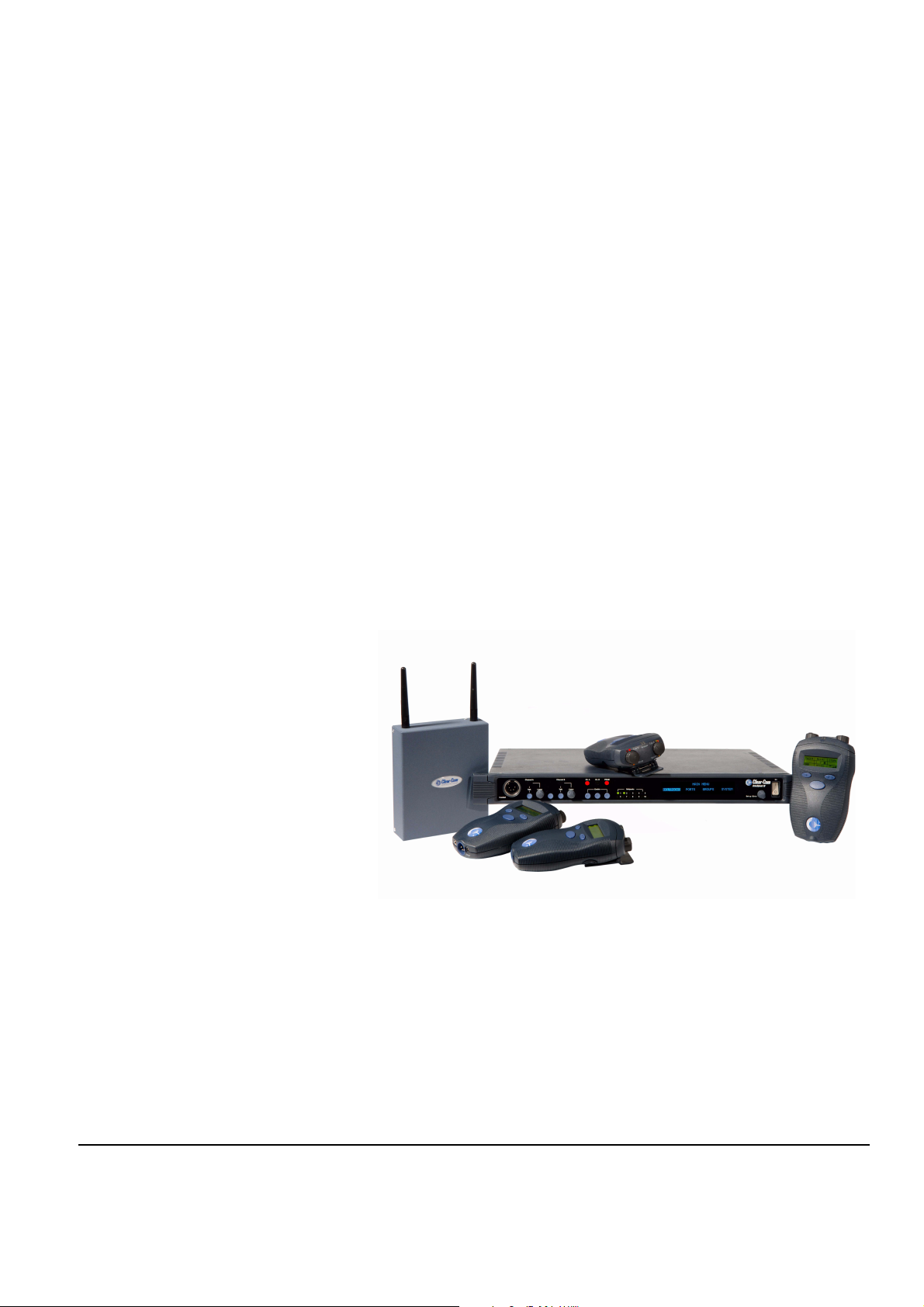
GETTING STARTED:
1
A FreeSpeak system
consists of three basic
elements: the basestation,
wireless beltpack, and
antenna.
AN INTRODUCTION
TO FREESPEAK
With a FreeSpeak wireless beltpack users can roam freely around a
studio or production facility while talking and listening to all, or
selected, members of the production team. With its six communication
routes, the beltpack gives users the flexibility to communicate quickly
and seamlessly with individuals or groups, and to change
communication routes as often as needed.
The award-winning FreeSpeak® technology, the world’s first wireless
system to include local route programming, crosspoint level control,
groups, and full non-blocking mixing facilities.
The system operates in the unlicensed 1.90 GHz band. With its unique
and innovative digital technology, which continually searches for
unused radio frequency (RF) channels, FreeSpeak avoids the noise
and interference issues associated with traditional wireless systems
using congested UHF and VHF bands.
With the basic three elements
the user can design a digital
wireless system for specific
requirements.
Clear-Com Communication Systems
FreeSpeak V2.0 Instruction Manual
Figure 1-1: A FreeSpeak Antenna, Beltpack, and Basestation
FreeSpeak allows a wireless system to be set up specifically t ailored to
local needs by locating antennas and beltpacks in areas where they
are needed most. And because the beltpacks operate in the
unlicensed 1.90 GHz frequency spectrum, there is no interference
with existing wireless systems, even those located in the same
production area.
FreeSpeak may be used stand-alone or connected with party-line
and/or digital matrix intercom systems. The basestation holds
1-1
Page 28

The FreeSpeak basestation
functions as a full-duplex
digital matrix switcher and
router for voice
communications.
Each antenna can support
communications with up to
five wireless beltpacks
operating within its coverage
zone.
connections for several wired interfaces, including party lines, 4-wire
sources, a program audio source, and a stage announce output
device. When wired to the basestation, these devices communicate
seamlessly with the wireless beltpacks. Party-line beltpacks and 4-wire
matrix stations and panels can key directly to wireless beltpack by
name.
FREESPEAK FEATURES
Features of FreeSpeak include:
• Basestation in one rack unit (1 RU).
• Up to twenty wireless beltpacks.
• Point-to-point and small group wireless communications.
• Up to six communication routes per beltpack.
• Party-line beltpacks, 4-wire devices, program audio source, and
stage announce output seamlessly included in communication
system.
• IFB functionality with up to five IFB audio sources configurable on the
basestation.
• Up to five standard groups configurable on the basestation.
• Up to five wireless party line groups configurable on the basestation.
• Up to ten remote transceiver/antennas create custom coverage
zones.
• Transceiver/antennas can be located u p to 1,0 00 meters (3 ,200 feet)
using 24 AWG cable or up to 500 meters (1,600feet) using 26 AWG
cable over CAT-5 cable from the basestation avoiding expensive RF
cable.
Note: It is recommended that shielded CAT-5 cable is used for all
FreeSpeak installation.
• Five-character labels for each beltpack and wired connection.
• Communication groups can be created, customized, and assigned to
beltpack keys.
• License-free operation in the 1.90 GHz band—above television and
other wireless communications.
• Frequency-hopping DECT technology automatically finds clear
spectrum.
• Base functions like a digital matrix; each beltpack has a “virtual port”
timeslot.
• Secure system—beltpacks are registered to a particular base and
can frequency hop.
1-2
Clear-Com Communication Systems
FreeSpeak V2.0 Instruction Manual
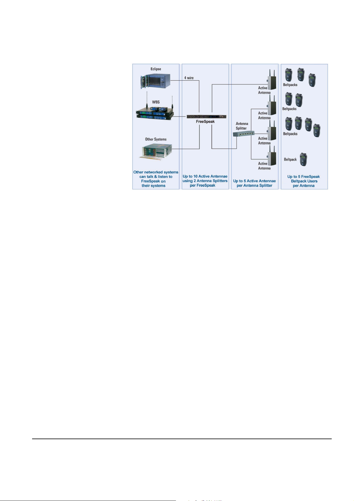
Page 29
• Two bases can connect locally via 4 wire ports or Party-lines only.
.
Figure 1-2: A FreeSpeak Digital Wireless Communication System
A FREESPEAK COMMUNICATION SYSTEM
A FreeSpeak system consists of three basic elements:
• The wireless beltpacks.
• The basestation that routes communication to and from wireless
beltpacks and other audio devices.
• The transceiver/antennas that provide custom coverage zones in
which four to five beltpacks can operate. Beltpacks can roam freely
between coverage zones.
FreeSpeak operates using a cellular network of antennas located
around a working environment. The antennas connect directly to the
FreeSpeak basestation with CAT-5 cable. Each antenna provides an
area or “cell” in which four to five full-duplex beltpacks can operate.
Figure 1-2 above shows an example configuration.
Beltpacks can roam among and between cells without dropping off
because each antenna continually signals a beltpack as to the
strongest available signal. When the signal from an antenna starts to
diminish due to the distance from a beltpack, the beltpack
automatically “hands off” its signal to the nearest antenna, ensuring
smooth transfer.
Clear-Com Communication Systems
FreeSpeak V2.0 Instruction Manual
1-3
Page 30

Figure 1-3: Configurations for a Studio and Large-Scale Broadcast Facility
Using an antenna splitter allows up to five antennas to be connected to
one base-station antenna port. A single FreeSpeak basestation
supports up to twenty beltpacks and up to ten antennas, giving a great
deal of flexibility in placing beltpacks where they are needed most, and
for providing wireless reliability. Figure 1-3 illustrates how a
FreeSpeak system can be set up to operate in a single studio or in a
large-scale permanent broadcast facility.
Note: Each antenna is designed to handle five beltpacks
simultaneously in good conditions. However, if interference
or propagation problems occur in an area, to ensure proper
operation and reliability, it may be more practical to install
four beltpacks for each antenna.
For zones which are likely to need coverage for five or more beltpacks
simultaneously it is recommended that a second antenna is installed.
Similarly , for good coverage for nin e or more beltpacks simult aneously,
a third antenna may be required.
1-4
Clear-Com Communication Systems
FreeSpeak V2.0 Instruction Manual
Page 31

IMPORTANT INSTALLATION INFORMATION
System Password
From release V2.0 onwards FreeSpeak basestations require a
password to be input in order to activate the base st ation when it is first
configured. The password requires the unique basestation system ID
and will normally be supplied with the installation CD for a new unit. If
an existing basestation is upgraded the basestation system ID must be
provided before an upgrade CD can be supplied.
Default Map
In V2.0 a default map has been added to help the first time user; the
map is designed to work like a simple party-line system.
Note that the analogue party-line ports are not included in the default
map as they would introduce an echo into the audio.
Clear-Com Communication Systems
FreeSpeak V2.0 Instruction Manual
Figure 1-4: Default Map Loaded
The Figure 1-4 above shows the default map on the configuration
editor; the two WPL (wireless party-lines) are programmed on the first
page and the other page are lef t un-programmed and will not be shown
on the beltpack.
1-5
Page 32

Figure 1-5: Beltpack Configuration with the Default Map
Figure 1-5 shows how each beltpack key will be configured by the
default map.
1-6
Clear-Com Communication Systems
FreeSpeak V2.0 Instruction Manual
Page 33

2
QUICK START
The following exercise demonstrates how to set up a simple
configuration of wired and wireless devices in a FreeSpeak system.
The user should have some familiarity with how FreeSpeak operates
before attempting this exercise. If not, please read through the manual
first, and then do the exercise.
To complete the exercise the following equipment will be needed. The
goal is to establish communication between these devices:
• A FreeSpeak system including two wireless beltpacks, an antenna,
and a basestation.
This exercise demonstrates
how to set up a simple
configuration.
In this exercise establi s h
communication between a
group of wired and wireless
devices.
• A 4-wire audio source, such as an Eclipse matrix.
• A wired beltpack, such as a Clear-Com 501 or 601 beltpack.
Specifically, this quick-start exercise shows how to:
• Wire the FreeSpeak basestation to a party-line beltpack, a 4-wire
audio source, and a FreeSpeak antenna.
• Assign labels to two FreeSpeak beltpacks.
• From the FreeS peak basestation, create a group containing the wired
and wireless devices.
• Initiate calls between members of the group.
Note: For a quick overview of the FreeSpeak programming
menus, refer to Appendix 2.
CONNECTING THE BASESTATION
To connect the FreeSpeak basestation to a party-line beltpack
1. Make sure the FreeSpeak basestation is powered off.
2. Connect an XLR cable from the “PL CH-A” connector on the rear of
the FreeSpeak ba sestation to a wired p arty-line beltpack, such as an
RS-601 (connection 1). See Figure 2-1 for an illustration.
Clear-Com Communication Systems
FreeSpeak V2.0 Instruction Manual
Note: Externally powered party-line equipment, FreeSpeak
splitters, and FreeSpeak active antennas should always be
connected and powered up before powering the FreeSpeak
basestation.
To Connect the FreeSpeak Basestation to a 4-wire matrix port
1. Connect a CAT-5 cable from the FreeSpeak basestation’s leftmost
4-wire audio port (labeled “4-Wire/Eclipse Ports”) to an external
4-wire audio source, such as an Eclipse matrix port (connection 2).
See Figure 2-1 for an illustration (shielded CAT-5 is recommend ed).
2-1
Page 34

Always power up external
party-line equipment,
FreeSpeak splitters, and
FreeSpeak active antennas
before powering the
FreeSpeak basestation.
To Connect the FreeSpeak Basestation to an Antenna
1. Connect a CAT-5 cable from transceiver port 1 on the FreeSpeak
basestation’s rear panel to a FreeSpeak antenna (connection 3).
See Figure 2-1 for an illustration (shielded CAT-5 is recommend ed).
2. Power up the basestation.
3. Power up the beltpacks.
If the beltpacks do not connect to the basest ation within 30 seconds,
check that they are registered to the basestation. If they are not,
refer to the chapter “FreeSpeak Configuration Editor” for instructions
on registering the beltpacks to the basestation.
Party-Line Beltpack
FreeSpeak Antenna
Eclipse Matrix
Channel A
1
Connect XLR cable to
party-line beltpack
POWER
90-260V, 50/60Hz
80 Watts
PL CH-A PL CH-B
Connect CAT-5 cable
to 4-wire audio source
23
Connect CAT-5 cable to
FreeSpeak antenna
PRGM IN
SA OUT
SA RLY
4-WIRE / ECLIPSE PORTS
1
2 3
BASE
LAN
LOOP
4
PC PROGRAM
TRANSCEIVER
1
2
FreeSpeak Base Station Rear Panel
Figure 2-1: Connect the FreeSpeak Basestation to the Wired Devices
4. To get the FreeSpeak into a “clean” state for the example below,
from the basestation’s front-panel display, scroll to and select
PORTS, then 4WIR1, then CALLS, then NONE (NONE is the last
element in the list.). Then also select PORTS, then PLCHA, then
CALLS, then NONE (See Figure 2-2).
2-2
Clear-Com Communication Systems
FreeSpeak V2.0 Instruction Manual
Page 35

Figure 2-2: Clear the Basestation’s Memory and Enable the Party Line
5. Enable the party line by pressing the CH A enable button on the
base staton’s front pan el until the CH A enab le light illuminates (See
Figure 2-2). Auto-nulling should be performed after the party line
circuit is connected. Pressing and holding the enable button
activates the auto-nulling.
Note: Be aware that a loud tone is generated in the party-line
beltpack’s headset during auto-nulling. This tone enables
the basestation to perform auto-nulling of the party line.
Clear-Com Communication Systems
FreeSpeak V2.0 Instruction Manual
2-3
Page 36

OVERVIEW OF BELTPACK OPERATION
2-4
Figure 2-3: Overview of Beltpack Operation
ASSIGNING LABELS TO THE FREESPEAK BELTPACKS
To assign a name (“label”) to FreeSpeak beltpack #1
1. From the basestation’s front-p anel display, use the setup/enter knob
to select BELTPACKS, then BPK01, and then LABEL.
Rotate the setup/enter knob until the desired item is highlighted.
Press the knob in to select the item.
2. Rotate the setup/enter knob again to select the alphanumeric
character to be edited, then push the setup/enter knob in to select
Clear-Com Communication Systems
FreeSpeak V2.0 Instruction Manual
Page 37

the character. Rotate the knob to select the character to replace it
with. Press the knob in to select the new character.
3. When selecting characters for the beltpack’s item label is complete
press the setup/enter knob again to save.
4. To exit the menu, select and then deselect (by pressing the knob
again) the fifth character in the menu.
5. The changes are saved and applied automatically five seconds af ter
the last time the setup/enter knob is pressed or turned. The
front-panel display flashes to indicate that the changes are being
saved and applied.
6. Repeat this entire process for the second wireless beltpack, BPK02.
CREATING A GROUP
To create a group
1. From the basestation’s front panel, use the setup/enter knob to
scroll to and select GROUPS, then GP#01, then MEMBERS.
If entries in the MEMBERS menu are already in the group these
menu entries are outlined. An outline around a menu entry means
that it is a member of the group. When an item is selected an outline
appears around it. When the item is selected again, the outline
disappears.
2. Select the following members of the group: 4WIR1, PLCHA, BPK01,
BPK02, so that only these entries are outlined.
3. To exit the Group Members menu, scroll to and select BACK from
the basestation’s front-panel menu.
4. The changes are saved and applied automatically five seconds af ter
the last time the setup/enter knob was pressed or turned. The
front-panel display flashes to indicate that the changes are being
saved and applied.
Clear-Com Communication Systems
FreeSpeak V2.0 Instruction Manual
ASSIGNING THE GROUP LABEL TO FREESPEAK BELTPACK KEYS
The next step is to assign the group label created in the prevous step,
GP#01, to the first key of each of the FreeSpeak wireless beltpacks.
T o assign the group label to the first key of FreeS peak bel tp ack #1
1. From the basestation’s front-panel menu select BELTPACKS, then
BPK01, then KEYS. A list will be displayed showing how the 3
pages of 2 keys are currently assigned on beltpack #1.
2. Select “Pg1-1” to edit the first key of the first page. A list of
destinations will be displayed this key can be assigned to. Rotate
the setup/enter knob clockwise until “GP#01” is highlighted, then
press the knob to select it. The basestation’s display should display
the key options.
• TLK - talk key
2-5
Page 38

• LIS - listen key
• T+L - talk and listen key
• DTL - dual talk and listen key
• FL - forced listen key
• TFL - talk and forced listen key
3. Select DTL using the setup/enter knob and press the knob to select
it.
4. Select BACK, then BACK again to return to the list of beltpacks.
5. The changes are saved and applied automatically five seconds af ter
the last time the setup/enter knob was pressed or turned. The
front-panel display flashes to indicate that the changes are being
saved and applied.
6. Repeat the procedure for beltpack #2.
CALLING THE GROUP FROM THE BELTPACKS
To call the group from beltpack #1
1. If beltpack #1 is not set to page #1 (indicated by the numbers in the
center of the display), use the beltpack’s left and right scroll buttons
to move to page 1.
The label under the left-hand rotary controller should now read
GRP01.
2. If the key is programmed to DTL on the basestation press the rotary
controller briefly to latch the listen path to “on” or press and hold the
rotary controller to talk.
2-6
• The red talk light and green listen light next to the rotary controller
should light.
• If the path is latched to Listen pressing and releasing the rotary
controller will delete the path and the red and green lights will
extinguish.
• If the rotary controller is being held to create a talk path releasing it
will delete the path. The red and green lights will be extinguished
when the talk path is deleted.
• Examine the wired beltpack attached to party-line channel A.
It should be possible to hear audio from beltpack #1 in the wired
beltpack’s headset. If the microphone of the wired beltpack is
opened the wireless beltpack should also be able to hear the
audio.
• The 4-wire device should have 2-way audio. The wireless
beltpack should be able to hear audio from the 4-wire device, and
the 4-wire device should be able to hear audio from the wireless
beltpack.
Clear-Com Communication Systems
FreeSpeak V2.0 Instruction Manual
Page 39

• Examine wireless beltpack #2. If it is on page #1, the green
(listen) light should be flashing and it should be possible to hear
audio from beltpack #1. At this point, beltpack #1 won’t be able to
hear audio from beltpack #2.
3. Press the leftmost rotary knob on beltpack #2, which is next to the
flashing green light.
All stations are able to hear beltpack #2 as well as beltpack #1. In
other words, all stations can hear each other.
4. Press the leftmost rotary controllers on beltpacks #1 and #2 briefly
to unlatch them. This deactivates all talk and listen paths.
CALLING THE GROUP FROM THE 4-WIRE AUDIO DEVICE
1. From the basestation’s front-panel menu, select PORTS, then
4WIR1, then CALLS, then GP#01.
The changes are saved and applied automatically five seconds after
the last time the setup/enter knob was pressed or turned. The
front-panel display flashes to indicate that the changes are being
saved and applied.
• All stations should now be able to hear the audio coming in from
the 4-wire device.
• On the two wireless beltpacks, the green (listen) lights should be
flashing, indicating an incoming call to group #1 from a member of
group #1.
2. Note that if the basestation is power cycled off and on again, the talk
paths from the 4-wire device are automatically re-established to the
wired beltpack and to the two wireless beltpacks.
3. It is possible to remove the talk paths from the 4-wire device to the
wired beltpack and to the two wireless beltpacks by selecting
PORTS, then 4WIR1, then CALLS, then NONE, from the
basestation’s front-panel menu.
4. Note that if the calling 4-wire port is included in the group that is
being called from the 4-wire device the 4-wire audio will not be
looped back to itself.
CALLING THE GROUP FROM THE WIRED PARTY-LINE BELTPACK
1. From the basestation’s front-panel menu, select PORTS, then
PLCHA, then CALLS, then GP#01.
The changes are saved and applied automatically five seconds after
the last time the setup/enter knob was pressed or turned. The
front-panel display flashes to indicate that the changes are being
saved and applied.
2. Ater a few seconds, when the wireless beltpacks reconnect, talk
from the wired beltpack’s microphone.
Clear-Com Communication Systems
FreeSpeak V2.0 Instruction Manual
2-7
Page 40

• Audio from the wired beltpack should be audible on the two
wireless belpacks, and on the 4-wire audio device.
On the wireless beltpacks. the green (listen) light should be
flashing, indicating an incoming call to group #1 from a member of
group #1.
• Audio from the 4-wire audio device will be audible from the wired
beltpack’s headset.
3. If the basestation is powered down and then up again, the talk paths
from the wired beltpack (on party-line channel A) are re-established
to the 4-wire device and to the two wireless beltpacks.
4. It is possible to remove the talk paths from the wired beltpack’ s party
line to the other devices by selecting PORTS, then PLCHA, then
CALLS, then NONE.This may also be done by disabling the party
line from the front panel of the FreeSpeak basestation by using the
CH A and CH B enable buttons provided that the party line is
powered from the basestation as this will remove the power rather
than the audio. It will not remove the talk paths if the party line is
externally powered.
CREATING A WIRELESS PARTY LINE
To create a wireless party line
1. From the basestation’s front panel, use the setup/enter knob to
scroll to and select GROUPS, then WP#01, then MEMBERS.
If entries in the MEMBERS menu are already in the wireless party
line these menu entries are outlined. An outline around a menu
entry means that it is a member of the wireless party line. When an
item is selected an outline appears around it. When the item is
selected again, the outline disappears.
2. Select the following members of the wireless partry line: 4WIR1,
PLCHA, BPK01, BPK02, so that only these entries are outlined.
3. To exit the Wireless Party Line Members menu, scroll to and select
BACK from the basestation’s front-panel menu.
4. The changes are saved and applied automatically five seconds af ter
the last time the setup/enter knob was pressed or turned. The
front-panel display flashes to indicate that the changes are being
saved and applied.
ASSIGNING THE WIRELESS PARTY LINE LABEL TO FREESPEAK BELTPACK KEYS
The next step is to assign the wireless party line label created in the
previous step, WP#01, to the first key of each of the FreeSpeak
wireless beltpacks.
2-8
To assign the wireless party line label to the first key of FreeSpeak beltpack #1
Clear-Com Communication Systems
FreeSpeak V2.0 Instruction Manual
Page 41

1. From the basestation’s front-panel menu select BELTPACKS, then
BPK01, then KEYS. A list will be displayed showing how the 3
pages of 2 keys are currently assigned on beltpack #1.
2. Select “Pg1-1” to edit the first key of the first page. A list of
destinations will be displayed this key can be assigned to. Rotate
the setup/enter knob clockwise until “WP#01” is highlighted, then
press the knob to select it. The basestation’s display should display
the key options.
• TLK - talk key
• LIS - listen key
• T+L - talk and listen key
• DTL - dual talk and listen key
• FL - forced listen key
• TFL - talk and forced listen key
3. Select DTL using the setup/enter knob and press the knob to select
it.
4. Select BACK, then BACK again to return to the list of beltpacks.
5. The changes are saved and applied automatically five seconds af ter
the last time the setup/enter knob was pressed or turned. The
front-panel display flashes to indicate that the changes are being
saved and applied.
6. Repeat the procedure for beltpack #2.
CALLING THE WIRELESS PARTY LINE FROM THE BELTPACKS
To call the wireless party line from beltpack #1
1. If beltpack #1 is not set to page #1 (indicated by the numbers in the
center of the display), use the beltpack’s left and right scroll buttons
to move to page 1.
The label under the left-hand rotary controller should now read
WPL01.
2. If the key is programmed to DTL on the basestation press the rotary
controller briefly to latch the listen path to “on” or press and hold the
rotary controller to talk.
• The red talk light and green listen light next to the rotary controller
should light.
• If the path is latched to Listen pressing and releasing the rotary
controller will delete the path and the red and green lights will
extinguish.
• If the rotary controller is being held to create a talk path releasing it
will delete the path. The red and green lights will be extinguished
when the talk path is deleted.
Clear-Com Communication Systems
FreeSpeak V2.0 Instruction Manual
2-9
Page 42

• Examine the wired beltp ack at t ached to p a rty-line ch annel A.
It should be possible to hear audio from beltpack #1 in the wired
beltpack’s headset. If the microphone of the wired beltpack is
opened the wireless beltpack should also be able to hear the
audio.
• The 4-wire device should have 2-way audio. The wireless
beltpack should be able to hear audio from the 4-wire device, and
the 4-wire device should be able to hear audio from the wireless
beltpack.
• Examine wireless beltpack #2. If it is on page #1, the green
(listen) light should be flashing and it should be possible to hear
audio from beltpack #1. At this point, beltpack #1 won’t be able to
hear audio from beltpack #2.
3. Press the leftmost rotary knob on beltpack #2, which is next to the
flashing green light.
All stations are able to hear beltpack #2 as well as beltpack #1. In
other words, all stations can hear each other.
4. Press the leftmost rotary controllers on beltpacks #1 and #2 briefly
to unlatch them. This deactivates all talk and listen paths.
CALLING THE WIRELESS PARTY LINE FROM THE 4-WIRE AUDIO DEVICE
1. From the basestation’s front-panel menu, select PORTS, then
4WIR1, then CALLS, then WP#01.
The changes are saved and applied automatically five seconds after
the last time the setup/enter knob is pressed or turned. The
front-panel display flashes to indicate that the changes are being
saved and applied.
• All stations should now be able to hear the audio coming in from
the 4-wire device.
• On the two wireless beltpacks, the green (listen) lights should be
flashing, indicating an incoming call to wireless party line #1 from
a member of wireless party line #1.
2. Note that if the basestation is power cycled off and on again, the talk
paths from the 4-wire device are automatically re-established to the
wired beltpack and to the two wireless beltpacks.
3. It is possible to remove the talk paths from the 4-wire device to the
wired beltpack and to the two wireless beltpacks by selecting
PORTS, then 4WIR1, then CALLS, then NONE, from the
basestation’s front-panel menu.
4. Note that if the calling 4-wire port is included in the wireless party
line that is being called from the 4-wire device the 4-wire audio will
not be looped back to itself.
2-10
Clear-Com Communication Systems
FreeSpeak V2.0 Instruction Manual
Page 43

CALLING THE WIRELESS PARTY LINE FROM THE WIRED PARTY-LINE BELTPACK
1. From the basestation’s front-panel menu, select PORTS, then
PLCHA, then CALLS, then WP#01.
The changes are saved and applied automatically five seconds after
the last time the setup/enter knob is pressed or turned. The
front-panel display flashes to indicate that the changes are being
saved and applied.
2. After a few seconds talk from the wired beltpack’s microphone.
• Audio from the wired beltpack should be audible on the two
wireless beltpacks, and on the 4-wire audio device.
On the wireless beltpacks. the green (listen) light should be
flashing, indicating an incoming call to wireless party line #1 from
a member of wireless party line #1.
• Audio from the 4-wire audio device will be audible from the wired
beltpack’s headset.
3. If the basestation is powered down and then up again, the talk paths
from the wired beltpack (on party-line channel A) are re-established
to the 4-wire device and to the two wireless beltpacks.
4. It is possible to remove the talk paths from the wired beltpack’ s party
line to the other devices by selecting PORTS, then PLCHA, then
CALLS, then NONE. This may also be done by disabling the party
line from the front panel of the FreeSpeak basestation by using the
CH A and CH B enable buttons provided that the party line is
powered from the basestation as this will remove the power rather
than the audio. It will not remove the talk paths if the party line is
externally powered.
Clear-Com Communication Systems
FreeSpeak V2.0 Instruction Manual
2-11
Page 44

2-12
Clear-Com Communication Systems
FreeSpeak V2.0 Instruction Manual
Page 45

OPERATING THE
3
FREESPEAK
BASESTATION
INTRODUCTION
The FreeSpeak basestation provides all of the intelligence and signal
routing for the FreeSpeak digital wireless intercom system. The
basestation is effectively a full-duplex digital matrix communications
system, with virtual “ports” for the wireless beltpacks rather than
physical ports.
In its memory, the basestation contains all of the labels and
communications paths assigned to each FS-BP beltpack, and this
information is sent to the beltpacks via the FS-T A transceive r/antennas
as soon as they are switched on and recognized by the base.
The basestation also functions as the interface between wired and
wireless communication devices. The two party-line intercom
connectors, four 4-Wire connectors, and program
input/stage-announce output each have their own full-duplex time slot.
They can be labeled, added to communication groups, and assigned to
beltpacks as desired. Additionally the program input o r one of the four
4-Wire connections can be assigned as IFB sources on the
basestation.
Clear-Com Communication Systems
FreeSpeak V2.0 Instruction Manual
3-1
Page 46

UNDERSTANDING FRONT-PANEL OPERATION
Figure 3-1: FreeSpeak Basestation Front Panel
Headset Connector
1
The 4-pin male XLR-type headset socket connects to Clear-Com
headsets and other headsets with 4-pin female connectors. This
headset connector is for the onboard two-channel intercom, with
controls just to the right of the connector.
2
& Channel A Talk Switch and Light/Listen
3
Level Knob
The channel A talk switch and associated light, and listen level knob,
allow full-duplex conversations with any FreeSpe ak wireless beltpacks
or other communications systems wired to the rear of the basestation
to which the onboard Channel A has been assigned. Assignments are
done via the front-panel programming.
The talk switch is momentary/latching, such that pressing it and
holding down will create a talk path that ends when the user releases
the switch, while quickly tapping it will latch the talk, and a second tap
will release it. The LED lights red when a talk is active.
Turning the listen level knob clockwise will allow the user to hear the
other party’s voice, increasing the level to maximum when fully
clockwise.
The audio level is shown on the beltpack screen next to the battery
display.
3-2
Clear-Com Communication Systems
FreeSpeak V2.0 Instruction Manual
Page 47

A/B Reply Button
4
Pressing this button will reply to the last caller to call A or B.
5
& Channel B Talk Switch and Light/Listen
6
Level Knob
The channel B talk switch and associated light, and listen level knob,
function the same as the controls for Channel A.
Party Line Channels A and B Enable Switches
7
The channel A and channel B enable switches and associated lights
activates the power only on the rear-panel to party-line intercom
channels A and B. Activating one or both of these switches enables
the power to that party line but does not affect the audio to the party
line which is always connected. These switches may be “locked” via
the front-panel SYSTEM programming menu so that they may not be
disengaged accidentally.
If the button is held in for more than 8 seconds autonulling mode will be
enabled for the current party line and the following message will be
displayed:
“Release button to begin autonulling”
When the button is release the basestation will perform an autonulling
on the current party line. On completion the following message will b e
displayed:
“Party line A Autonulling complete”
for party line A.
Program Audio Enable Switch and Light
8
This latching switch makes any program audio signal that enters via
the rear-panel line-level 3-pin XLR connector available to be assigned
to wireless beltpacks, either separately or mixed with communications
groups. This switch may be “locked” via the front-panel SYSTEM
programming menu so that it may not be disengaged accidentally.
Antenna Light Display
9
These green LEDs, one for each of the ten antennas that the base will
support, light when an antenna is connected and ready.
Clear-Com Communication Systems
FreeSpeak V2.0 Instruction Manual
3-3
Page 48

Display Screen
10
The display screen shows all of the menus and programming options
that are available within the FreeSpeak system. The user can select a
particular beltpack and view all of its current t alk/listen assignment s, or
see all of the current members of a particular group. Via the screen
and rotary encoder, labels (5-character user names) can be created
and/or changed, new members assigned to groups, input and output
levels adjusted, and so on.
Setup/Enter Knob
11
The setup/enter knob is used to scroll through the various menu
options within the FreeS pea k basestation, in order to discover specific
information regarding users or to program communications routes and
groups. Turning the knob clockwise scrolls display items toward the
right, and turning the knob counterclockwise scrolls display items
toward the left.
When a desired menu item is highlighted, pushing the setup/enter
knob inward will select that item. The lists of available beltpacks and
groups typically span two or more screens, so when the highlight is at
the leftmost or rightmost part of the screen and the user continues to
turn the rotary encoder in that direction, the display will jump to the
next screen selections (Example: in the beltpack sections, the first
screen shows beltpacks 1 through 5, and the second shows 6 through
10.)
Pressing and holding the Setup/Enter knob for more than three
seconds will return the display to the battery monitor.
Power Switch
12
The power switch will turn the FreeSpeak basestation on and off.
3-4
Clear-Com Communication Systems
FreeSpeak V2.0 Instruction Manual
Page 49

CONNECTING THE
4
The FreeSpeak basestation
connects to several wired
interfaces that can
communicate with the
wireless beltpacks.
FREESPEAK
BASESTATION
The FreeSpeak basestation connects to the following wired interfaces
through its rear-panel connectors:
• Basestation to AC power
• Basestation to party-line channels A and B
• Basestation to program audio source
• Basestation to stage announce output
• Basestation to stage announce relay
• Basestation to 4-wire matrix ports
• Basestation to a second basestation (not used)
• Basestation to a PC
• Basestation to transceiver antennas
POWER
90-260V, 50/60Hz
80 Watts
1
UNDERSTANDING THE BACK-PANEL CONNECTORS
PL CH-A PL CH-B
2
1 - Power Connector
2 - Party Line Channel A Connectors
3 - Party Line Channel B Connectors
4 - Program Input
5 - Stage Announce Output
6 - Stage Announce Relay
3
PRGM IN
SA OUT
4-WIRE / ECLIPSE PORTS
1
SA RLY
4
Figure 4-1: FreeSpeak Basestation Back Panel
6
5
23
7
7 - 4-Wire Matrix Ports
8 - Base Loop Connector (not used)
9 - LAN Connector
10 - PC Connector
11 - Transceiver Connectors
BASE
LAN
LOOP
4
8
PC PROGRAM
9
10
TRANSCEIVER
1
11
2
Clear-Com Communication Systems
FreeSpeak V2.0 Instruction Manual
4-1
Page 50

IEC Power Connector
1
The 3-conductor AC power connector and universal power supply
accepts voltages from 90 to 250 volts, at 50/60 Hz. Power
consumption is 80 watts.
Party Line Channel A Connectors
2
The FreeSpeak basestation provides two pairs of party-line
connectors, labeled “Channel A” and “Channel B.” Each pair of female
and male 3-pin XLR connectors joins a channel of party-line intercom
to the FreeSpeak, allowing communication between the wired
party-line equipment and FreeSpeak wireless beltpacks. Input and
Output level control is set via the front-panel display programming.
The second connector of each pair is a loop-through, so that the user
can continue the connection to another FreeSpeak basestation or to
another party-line beltpack or station. This connector auto-detects a
connection with a powered party-line channel (30-VDC on Pin 2), and
the basestation’s internal 200-ohm party-line termination and DC
voltage to power PL beltpacks is not activated.
Alternatively, when a wired, unpowered party-line beltpack (up to four)
is connected to PL CH-A with standard two-conductor shielded
microphone cable, the basestation engages the 200-ohm termination
and supplies 24-VDC to the beltpack(s) – allowing them to operate and
communicate with the wireless beltpacks in the system.
Party Line Channel B Connectors
3
These connectors are the same as those for PL CH-A.
Program Input Connector
4
This female 3-pin XLR connector accepts a line-level audio signal from
an outside source such as a mixing console or audio player. It is
transformer-isolated. Level adjustment is done via the front-panel
display programming. The program input can be assigned as an IFB
source from the front panel.
Stage Announce Output Connector
5
This male 3-pin XLR connector allows a line-level audio signal,
typically from wireless beltpacks or 4-Wire sources, to be sent to a
paging system or other audio system. It is transformer-isolated. Level
adjustment is done via the front-panel display programming. More
than one audio source at a time can be routed to the S t age Announce,
with the audio being combined to give a single audio output.
4-2
Clear-Com Communication Systems
FreeSpeak V2.0 Instruction Manual
Page 51

Stage Announce Relay
6
This DB-9 male connector provides a relay closure that is triggered
simultaneously with the SA Output. The relay may be used to open an
audio pathway for the signal from the SA Output, or could also be used
to activate a light or lock or some other device. The relay may be wired
for normally closed or normally open operation, and the signal appears
on pins 1 & 6 or 2 & 6. It is rated to a maximum of 30-VDC at 1 amp.
4-Wire Matrix Ports
7
These four RJ-45 connectors can connect four full-duplex (input pair
and output pair) audio connections from a 4-wire communications
device, digital matrix intercom, or similar – making them available to
the wireless beltpacks. Any of the 4-wire ports or the program input
can be assigned as IFB sources from the front panel.
Each of these connectors has its own time slot, and can be addressed
separately from a beltpack, or combined with other beltpacks and
rear-panel connectors in a group. Level adjustment is done via the
front-panel display programming.
Base Loop Connector (not used)
8
The connector has no function in Freespeak V2.0.
LAN Connector
9
This RJ-45 connector allows the basestation to be connected to a LAN
for system software upgrades and configuration downloads from the
Configuration Editor. It is a 10BaseT Ethernet port.
PC Connector
10
This female DB-9 connects to a PC computer for firmware updates and
monitoring of the system configuration. It functions as a serial port.
Transceiver Connectors
11
These two RJ-45 connectors connect the basestation to two remote
FS-TA transceiver/antennas or antenna splitters.
Each wired transceiver/antenna communicates with five wireless
beltpacks. Each antenna splitter provides connection for five
transceiver antennas. providing communication with up to a maximum
of 10 beltpacks depending upon available bandwidth.
Clear-Com Communication Systems
FreeSpeak V2.0 Instruction Manual
Note: To meet FCC emissions requirements a ferrite must be
fitted on any CAT-5 cable plugged into either of the two
4-3
Page 52

ports labeled “tranceivers.” The ferrite should be fitted at
the basestation end of the CAT-5 cable. Position the ferrite
as close to the basestation as possible. A suitable ferrite is
available from Wurth Elektronix. The part number is 742 711
32.
Note: It is recommended that shielded CAT-5 cable is used for
FreeSpeak systems.
CONNECTING TO PARTY-LINE INTERCOM SYSTEMS
Up to two channels of party-line intercom can be connected to the
FreeSpeak basestation. The descriptions below will discuss
connections with Clear-Com and compatible party-line, RTS party-line,
the ability of FreeSpeak to power up to four Clear-Com beltpacks by
itself, and the front-panel settings associated with these party-line
connections.
Using the front-panel display and rotary encoder, the user may go into
the PORTS menu, select the desired party-line channel, and create a
five-character alphanumeric label for it. This is the label that would
then appear on any FreeSpeak wireless beltpacks to which that
party-line connection was assigned for communications. In the
GROUPS menu, the party-line connection can be assigned as a
member of any of the groups, as desired.
CLEAR-COM AND COMPATIBLE PARTY-LINE
Clear-Com and Clear-Com-compatible wired party-line intercoms
connect to the PL CH-A and PL CH-B connectors in a similar manner
to connecting beltpacks or remote stations to the intercom line.
Typically that wired intercom connection would have a 30-VDC current
on Pin 2, coming from a main station or an intercom power supply. The
second connector in the pair may be used as a loop-through to go to
other wired party-line stations or beltpacks, or to a second FreeSpeak
basestation. The pinout for party line connector is shown in table
Table 4-1.
PIN DESCRIPTION
1 Ground (shield)
2 Power
3Audio
Table 4-1: Party Line Pinout
To connect party-line equipment to the basestation
4-4
Clear-Com Communication Systems
FreeSpeak V2.0 Instruction Manual
Page 53

1. Check that the party-line LED on the front-panel is out, which
indicates that the party-line connection is disabled from the
basestation.
2. Connect, and if appropriate, power up, the external party-line
equipment.
3. Enable the party line by pressing the “enable” button on the
basestation’s front panel.
The basestation detects power and termination settings when the party
line is enabled by pressing the “enable” button on the basestation’s
front panel, or when the basestation is powered up after having
enabled the party line. The basestation remembers that the party line
is enabled when it powers up.
When the FreeSpeak basestation detects a wired party line being
connected with 30 VDC on Pin 2, it does not enable the 24-VDC power
supply that the FreeSpeak basestation supplies to the connector to
support a handful of locally connected wired party-line beltpacks. The
basestation then appears to the wired party-line system as a remote
station.
The first call to a Party Line channel A or B results in the call alert and
subsequent ones do not give any further alerting unless the Party Line
channel buttons on the basestation are toggled. This prevents all calls
giving alerts when this is not necessary.
CONNECTING DIRECTLY TO CLEAR-COM PARTY-LINE BELTPACKS
PL CH-A and PL CH-B have the ability to directly support up to four
Clear-Com RS-501 or RS-601 party-line beltpacks each, without any
other connection to a wired party-line system. This feature gives the
convenience of being able to add a few wired beltpacks when needed
to a FreeSpeak installation.
Connect a standard two-conductor shielded microphone cable to the
PL CH-A connector, and then connect it to a Clear-Com single-channel
party-line beltpack. The basestation will detect that the beltpack has
been connected, and will enable the required 200-ohm termination,
and will supply 24-VDC to Pin 2 to power the beltpack(s).
It is possible to daisy-chain up to four beltpacks, or use an intercom
XLR splitter at the basestation to feed mic cables connected to the
individual beltpacks. Because it is a 24-volt rather than a 30-volt
current, the maximum length of cable that can be connected (the sum
of all of the runs) will be shorter than what is expected with the
standard party-line voltage. Do the same with PL CH-B to support an
additional four beltpacks.
To connect to the party line
Clear-Com Communication Systems
FreeSpeak V2.0 Instruction Manual
1. From the main menu, scroll to PORTS and select by pressing the
setup/enter knob in.
2. Scroll to PLCHA or PLCHB and press to select.
4-5
Page 54

The SELECTED PORT screen appears.
3. Scroll to and select CALLS.
The CALL DESTINATION screen appears.
4. Select the port or group to be connected to the party line by scrolling
to it and pressing the rotary encoder . Doing so creates a route to the
selected destination—this port or group can now hear the activity on
the party line. (Note: this option can also be set to NONE.)
5. Select TYPE from the menu.
6. Select either Clear-Com, Drake, or RTS.
The basestation automatically sets the termination, audio levels,
and call signaling options for the selected party-line system.
Note that the Basestation does not detect the RTS call signal.
7. If the changes are saved the route will be reinstated on power up.
Note: Suggested settings for a party line connection are that the
VOX should be set to -26dB, the gain output to -6dB and the
input to 0dB.
CONNECTING TO AN RTS™ WIRED BELTPACK
FreeSpeak can only transmit and receive audio from channel 2 of an
RTS wired beltpack. Connect using a standard XLR cable. Ensure that
the party-line type is set to “RTS” using the menu on the basestation
before enabling the party line. See the chapter “Programming a
System from the Basestation” for more information.
Warning:Previous versions of this manual described a cable
which would allow access to channel 1 of a dual channel
RTS beltpack. DO NOT attempt to use a cable like th is as
it could result in damage to the FreeSpeak basestation.
FRONT-PANEL ADJUSTMENTS FOR PARTY-LINE CONNECTIONS
To connect the party-line channels to FreeSpeak and make the
communication available to the rest of the system, press the CH-A
and/or CH-B enable switches. The LED will light, and the connection is
made. To disconnect the party-line connections, press these switches
again. The switch may be “locked” in the SYSTEM menu so that the
party lines may not be disconnected.
Because party-line intercom does not have global level control on a
channel, input and output level controls are provided via the front panel
programming. Scroll to PORTS on the main display screen and press
the rotary encoder to select. Scroll to PLCHA or PLCHB and press to
select. Select LEVELS, then select the input or output level. This
notation is relative to the basestation–input level refers to the level at
which everyone else hears the party line, and output level refers to the
level at which the users on the party line channel hear everyone else.
4-6
Clear-Com Communication Systems
FreeSpeak V2.0 Instruction Manual
Page 55

Use the rotary encoder to adjust the numerical level—clockwise to
increase the level and counter-clockwise to decrease the level.
Make the estimated changes in level and press the rotary encoder to
save the changes. Test the levels between the party line and
FreeSpeak beltpack, and make additional changes as needed. When
the levels are set as desired, press to select and the display will go to
the previous INPUT/OUTPUT screen. When both are adjusted, select
BACK on each screen until the main screen is displayed.
Users connected to the basestation can be forced to listen to the
activity on the party line by initiating a “call”.
For more information on programming the basestation, see the chapter
“Programming a System from the Basestation”.
Clear-Com Communication Systems
FreeSpeak V2.0 Instruction Manual
4-7
Page 56

TROUBLESHOOTING PARTY-LINE CONNECTIONS
Reducing FreeSpeak Beltpack echo when talking to a analogue party-line
If the basestation and beltpack are not set up correctly the FreeSpeak
user will experience an echo when talking to a party-line (either directly
or via a group or a wireless party-line). The echo is caused by either
local audio coupling in the headset due to the microphone gain being
set too high or audio reflections from the party-line that can minimized
by setting a VOX gate on the party-line and the party-line being auto
nulled.
How to set the microphone gain in the beltpack
When using a CC-260 or CC-95 the microphone gain should be set at
55dB (55dB is the default setting).
Note: If the microphone gain is set higher than 55dB this can
introduce audio coupling between the ear phone and the
microphone.
Include the Party-Line channel inside a Wireless Party-Line group
It is recommended that when connecting to an analogue party-line
system that the user includes the wireless party-lines (WPL). The
WPLs reduce the variation in audio levels heard when talking to
analogue party-lines. The WPLs are created in the configura tion editor
in a similar way to a user creating a group.
How to set the VOX gating level on the Party-Line connected to the Basestation
4-8
Figure 4-2: VOX Gating Level on Party Line Connection
Clear-Com Communication Systems
FreeSpeak V2.0 Instruction Manual
Page 57

The VOX gate allows the user to set limits to the audio that will be
passed from the party-line to the basestation mixer; by setting the VOX
level at the correct level the user can cut the audio reflections (which
cause the echo) from the party-line when a wireless beltpack user
speaks. This is achieved when the VOX level is set above the audio
level of the reflections, thus allowing a party-line user’s voice to pass
through the VOX gate in the basestation mixer but the VOX gate will
reject the audio reflections.
Note: If both the party-line user and the FreeSpeak user speak at
the same time, the FreeSpeak user may hear the echo as the
audio reflections piggy back the party-line audio.
Clear-Com Communication Systems
FreeSpeak V2.0 Instruction Manual
Figure 4-3: VOX Gate Setting Examples
Note: If the FreeSpeak beltpack users shouts or increases the
microphone gain into the beltpack the echo might return if
the audio reflects are above the VOX gate level.
Auto null the Party-Line channel at the Basestation
Party-lines connected to the base station can be auto nulled by first
enabling party-line channel by pressing the party-line button on the
front of the basestation.
The auto nulling is then activated by pressing and holding the enable
party-line button; the base station will go then into a auto null routine.
4-9
Page 58

WIRELESS PARTY LINE
The FreeSpeak basestation provides five wireless party line groups
which allow up to twenty eight members to be connected together in a
conference call. The beltpack keys assigned to the wireless party line
group are assigned as dual talk and listen and p arty lines connected to
the group are assigned as talk and listen.
When a beltpack or party line talks to a wireless party line group the
talk signal from the beltpack or party line is subtracted from the listen
signal to remove the sidetone resulting from the users voice being
looped back in the conference audio, leaving only the audio from othe r
members.
Figure 4-4: Wireless Party Line Audio Flow
This facility allows conferencing over a large area between a mix of
beltpacks, party line stations and Eclipse system panels through a
FreeSpeak basestation.
CONNECTING TO 4-WIRE AND DIGITAL MATRIX INTERCOM
Up to four channels of 4-wire/digital matrix intercom can be connected
to the FreeSpeak basestation. The descriptions below will discuss
connections with Clear-Com Matrix Plus digital matrix, Clear-Com
Eclipse digital matrix, other brands of digital matrix intercoms, other
4-wire audio devices, and the front-panel settings associated with
these 4-wire connections.
To connect the basestation to a matrix port:
1. Scroll to PORTS on the main display screen and press the rotary
encoder to select.
2. Scroll to 4-WIRE and press to select.
4-10
Clear-Com Communication Systems
FreeSpeak V2.0 Instruction Manual
Page 59

3. Scroll to CALLS and press to select.
4. Select the port or group to create an audio path to and press to
select. Doing so creates a route to the selected destination—this
port or group can now hear the activity on the party line. (Note: this
option can also be set to NONE.)
5. Once the changes have been saved, the route will be reinstated on
power up.
Note: Call signalling is not currently supported on 4-wire
connections.
In the GROUPS menu, the 4-wire port can be assigned as a member
of any of the groups, as desired.
4-Wire Pinout
The pinout for the RJ-45 4-wire port is shown in Table 4-2.
RJ-45 CONNECTOR
AT BASE STATION PORT
8765
Figure 4-5: Front View of RJ-45 Connector
4
3
2
1
Clear-Com Communication Systems
FreeSpeak V2.0 Instruction Manual
4-11
Page 60

Pin Description
1 Not used
2 Not used
3 Audio Output +
4 Audio Input +
5 Audio Input 6 Audio Output 7 Not used
8 Not used
Table 4-2: FreeSpeak Basestation 4-Wire Pinout
CONNECTING WITH CLEAR-COM MATRIX PLUS
The connection between a Matrix Plus digital intercom port and a
FreeSpeak 4-wire port is accomplished with a standard 4-pair
straight-through CAT-5 data cable with RJ-45 connectors on both
ends. In the current generation of FreeSpeak, the audio input and
audio output pairs are all that will be used.
In the Matrix Plus PGM-WIN configuration software, set the matrix port
that is connected to the FS-BASE basestation 4-wire port to “4-Wire”. If
the label of this FreeSpeak 4-wire port is to be put onto more than one
intercom panel within the matrix system, and any and all people who
have activated a talk/listen to that port to be able to hear each other, as
well as hearing the person talking to them from the FreeSpeak
wireless beltpack, also check “Party-Line Enable” for that 4-Wire
connection in the configuration software.
4-12
Within the FreeSpeak Basestation configuration software, the user can
adjust the input and output level for that port. Alternately, the input and
output levels can be adjusted on the FreeSpeak basestation for the
particular 4-wire port, using the front-panel display. Repeat the
procedure for each FreeSpeak 4-wire port that is connected with the
Matrix Plus system. Note that FreeSpeak does not currently generate
a call signal to the Matrix port.
CONNECTING WITH CLEAR-COM ECLIPSE DIGITAL MATRIX
The procedure to connect between a FreeSpeak 4-wire port and the
Eclipse digital matrix is similar to that of Matrix Plus 3. An identical
connection is made with 4-pair straight-through CAT-5 cable between
an Eclipse port and the FreeSpeak port.
Within the Eclipse Configuration System software (ECS), set the port
to “Direct.” This will allow intercom stations in the Eclipse system to
converse with the FreeSpeak basestation and beltpacks. Because
Clear-Com Communication Systems
FreeSpeak V2.0 Instruction Manual
Page 61

there is not a “Party-Line Enable” within Eclipse, if several users of
intercom stations connected with Eclipse need to hear each other as
well as the wireless FreeSpeak beltpack, another procedure will need
to be added. Within the configuration software, the user would create a
new party-line label, with members including the desired intercom
stations and the particular FreeSpeak 4-wire port. That label would
then be assigned to a key on each of the intercom stations, allowing
connection with the FreeSpeak 4-wire port and the other members of
the new party-line.
Within the FreeSpeak Basestation configuration software, the user can
adjust the input and output level for that port. Alternately, the input and
output levels can be adjusted on the FreeSpeak basestation for the
particular 4-wire port, using the front-panel display. Repeat the
procedure for each FreeSpeak 4-wire port that is connected with the
Eclipse system.
CONNECTING WITH OTHER DIGITAL MATRIX INTERCOM SYSTEMS
Because FreeSpeak features standard 4-wire ports, with an input pair
and an output pair, virtually any 4-wire signal can be connected with it.
Make sure to properly match the input and output pairs between the
digital matrix port and the FreeSpeak 4-wire port (see diagram below).
The pinouts for the first two 4-wire ports contain both audio and data
connections, though the data connections are not currently used.
Those pinouts are shown in the following table.
PIN FUNCTION
1 Data Tx+
2 Data Tx–
3 Audio Out+
4 Audio In+
5 Audio In–
6 Audio Out–
7 Data Rx+
8 Data Rx–
Table 4-3: Pinouts for Connecting to Other Digital Matrix Intercom Systems
The remaining two 4-wire connections are audio only, and the data
connections are unterminated (see Table 4-2).
Within the configuration software of the other digital intercom system,
configure its connected port to 4-wire or similar. Adjust the input and
output levels either at matrix side or within the FreeSpeak front-panel
display for the particular FreeSpeak 4-wire port.
Clear-Com Communication Systems
FreeSpeak V2.0 Instruction Manual
4-13
Page 62

CONNECTING WITH OTHER 4-WIRE DEVICES
Various other 4-wire audio devices can be connected with FreeSpeak.
The Clear-Com EF-701M 4-wire interface can be used to attach
additional party-line channels to FreeSpeak, converting them from
party-line on the wired side to 4-wire on the FreeSpeak side.
The Clear-Com IF4W4 interface can be used similarly. The audio input
side of the FreeSpeak 4-wire connectors could be used for additional
program or other audio inputs that could then be accessed by
FreeSpeak beltpacks. The audio output side of the FreeSpeak 4-wire
connectors could be used to route a FreeSpeak wireless beltpack
user’s voice out of the system for paging or other reasons, similar to
the SA OUT connector.
When using the FreeSpeak 4-wire ports in this way, make sure that
proper connections are made between FreeSpeak and the other
device. Adjust the input and/or output levels either at the 4-wire device
or within the FreeSpeak front-panel display for that particular 4-wire
port.
CONNECTING TO A PROGRAM AUDIO SOURCE
FreeSpeak can connect with a program audio source, making it
accessible to be assigned by itself to a communication path to one or
more FS-BP wireless beltpacks, or to be added to a group with other
communications and assigned to beltpacks. Using the two separate
rotary encoder volume controls on the beltpack, the user can monitor
the program on one control while talking and listening on an intercom
channel with the other.
The balanced female 3-pin XLR connector accepts a standard audio
signal from a mixing console or similar, with Pin 1 ground, Pin 2 audio
hot (+), and Pin 3 audio cold (-).This connector is transformer-isolated.
To make the program input signal available to the system, the
front-panel PRGM enable button must be activated/on. The red LED
above it will light, indicating that it is now available. This front-panel
switch may be “locked” to prevent accidental disengagement, using
the front panel display.
Using the front-panel display and rotary encoder, the user may select
PORTS and give the connector a five-character alphanumeric label.
The user may assign that program input by itself to a beltpack using
the BELTPACKS menu, or use the GROUPS menu to assign the
program input to any group or wireless party line. Program input can
be assigned to multiple groups or wireless party lines using the
GROUPS menu.
4-14
Clear-Com Communication Systems
FreeSpeak V2.0 Instruction Manual
Page 63

IFB CONFIGURATION
One of five FreeSpeak basestation inputs can be defined as a source
for an IFB. These inputs are the Program Input and the four 4-Wire
ports. All the 4-Wire ports, party line channels, beltpacks, wireless
party lines and stage output can be defined as IFB destinations.
Up to ten IFB key configurations can be set up that group together an
IFB source and a number of IFB destinations and set the dimming level
for that IFB key configuration.
IFB Source IFB Destination IFB Talks
Program Audio Four-wire 3
All beltpacks
Four-wire 4
All beltpacks
Four-wire 3 Four-wire 4
All beltpacks
All beltpacks
Four-wire 4 Four-wire 3
All beltpacks
All Beltpacks
Table 4-4: IFB Key Configurations
An IFB talk is a panel or beltpack with a key set up to talk to the IFB
key configuration. Whenever an IFB talk key is pressed the audio from
the IFB source to the IFB destinations configured in the IFB key
configuration is dimmed by the set amount and the audio from the IFB
talk is heard by all the IFB destinations set up in that IFB key
configuration.
Clear-Com Communication Systems
FreeSpeak V2.0 Instruction Manual
Figure 4-6: IFB Audio Path
4-15
Page 64

The IFB source audio will be dimmed on the IFB destinations for as
long as the IFB talk key is active. When the IFB talk key is released
the IFB source audio to the destinations will return to normal level.
CONNECTING TO THE STAGE ANNOUNCE OUTPUT
The stage announce feature allows a talker to route their voice to an
external paging system or other audio destination by pressing one of
the rotary encoders to which the SA OUT connector is assigned. The
adjacent SA RELAY is simultaneously triggered. One beltpack user at
a time may use this feature, though the capability may be assigned to
any or all of the wireless beltpacks, as desired.
Connect a microphone cable to the male 3-pin XLR connector on the
rear of the FreeSpeak basestation, and connect the other end to the
external audio system. When the output is activated, the beltpack
user’s voice will be sent at line level to the audio system. The audio
output ceases when the beltpack user stops pressing the rotary
encoder; it is good practice to make sure that any rotary encoder to
which the SA OUT is assigned is set to momentary/non-latching mode.
PIN FUNCTION
1 Normally Closed
2 Normally Open
3 N/C (no
connection)
4N/C
5N/C
6Pole
7N/C
8N/C
9N/C
Table 4-5: Pin Assignments for Stage Announce Connector
The associated SA RELAY can be assigned to open an audio route for
the paging or announcement, or can be assigned to initiate any other
event such as turning on a light or activating a lock. It is rated at a
maximum of 30 VDC at 1 ampere. The relay can be wired to be either
normally open or normally closed, using the pinout information in
Table 4-5.
4-16
Clear-Com Communication Systems
FreeSpeak V2.0 Instruction Manual
Page 65

CONNECTING TO A PC
CONNECTING VIA THE SERIAL PORT
The PC serial port on the rear of the FreeSpeak basestation is mainly
used for firmware version upgrades of the system.
A specially wired cable is required for these updates, co nsisting of two
9-pin D-type connectors for the PC and the FreeSpeak ends. On the
FreeSpeak end, a male 9-pin D connector is used, and is wired as
follows in relation to the D connector pins on the PC end. Pin 2 goes to
pin 3, pin 3 goes to pin 2, and pin 5 goes to pin 5; in other words, the
data Tx and Rx lines on pins 2 and 3 are reversed. Those are the only
wiring connections on the FreeSpeak end of the cable.
PC CONNECTION (9-PIN F) BASESTATION (9-PIN M)
1N/C
23
32
4N/C
55
6N/C
7N/C
8N/C
9N/C
Table 4-6: Pinout for Cable to Upgrade Basestation Firmware
On the PC end, a female 9-pin D connector is used. Make sure that the
data connections of pin 2 to pin 3 and pin 3 to pin 2 are followed, and
that pin 5 goes through to pin 5. Then short pins 1, 4, 6, and 8 together
on the PC end of the cable. The cable will now be ready to use with the
any upgrade files from the factory. Table 4-6 gives the pin
configuration for this cable. Table 4-7 shows the pin configuration for
the cable used to upgrade beltpack firmware.
Clear-Com Communication Systems
FreeSpeak V2.0 Instruction Manual
4-17
Page 66

PC CONNECTION
(9-PIN F)
1N/C
2tip
3ring
4N/C
5 screen
6N/C
7N/C
8N/C
9N/C
Table 4-7: Pinout for Cable to Upgrade Beltpack Firmware
BELTPACK (3.5 mm
jack)
CONNECTING VIA THE LAN PORT
This connection is used for rapid firmware updates, as well as in the
future for system configuration and intelligent connection with the
Eclipse digital matrix. It is wired as a standard Ethernet connection.
The basestation has a fixed IP address. This can be found by selecting
SYSTEM and then INFO from the front-panel display menu. Refer to
the chapter “FreeSpeak Toolkit” for more information on using the LAN
port to upgrade firmware.
CONNECTING TO TRANSCEIVER/ANTENNAS (FS-TA)
CONNECTING ONE TRANSCEIVER/ANTENNA (FS-TA) DIRECTLY TO A TRANSCEIVER PORT
A FS-TA transceiver/antenna connects to the transceiver port on the
FreeSpeak basestation using a standard 4-pair CAT-5 data cable with
RJ-45 connectors. It may be located up to 1,000 meters from the
basestation if 24AWG cable is used for 500 meters if 26AWG cable is
used creating a coverage area for five FS-BP wireless beltpacks in that
location. The port is able to provide the required power to the
transceiver/antenna at a distance of up to 300 meters (approximately
900 feet); beyond that distance, the FS-TA transceiver/antenna must
be locally powered via its in-line external universal power supply.
Note: It is recommended that shielded CAT-5 cable is used.
To know that a FS-TA transceiver/antenna is active, observe the green
power LED and the yellow signal LED on the face of the unit where the
RJ-45 connector is connected. Both must be lit. Also, wireless
beltpacks in the vicinity of the active transceiver/antenna will be
4-18
Clear-Com Communication Systems
FreeSpeak V2.0 Instruction Manual
Page 67

connected to the system and their displays will show labels and other
information.
Using both transceiver ports, a basestation may be connected with up
to two transceiver/antennas via a direct connection with the
basestation. For the best, most reliable coverage, it is advisable to use
a minimum of two transceiver/antennas in any installation, positioned
in different locations in the coverage area. When more FS-TA’s are
required to support a larger coverage area or more wireless beltpacks,
an antenna splitter will need to be introduced between the basestation
and the transceiver/antennas.
Note: In some situations, particularly in outdoor venues,
interference from non-DECT sources can severely reduce
the range of the system. In these cases we recommend a
site survey as described in Chapter 8, “Installing a System”.
CONNECTING TRANSCEIVER/ANTENNAS WITH A SPLITTER (PD2203)
A splitter (PD2203) will connect up to five transceiver/antennas to one
of the transceiver ports on the FreeSpeak basestation, creating up to
five coverage zones that can be overlapped to make large areas
where FS-BP wireless beltpacks can have continuous coverage. The
use of the splitter also extends the distance that the FS-TA transceiver
antennas can be located from the basestation to 2,000 metres (6,400
feet) if 24AWG cable is used or 1.000 metres (3,200 feet) if 26AWG
cable is used (assuming the same type of cable to used to connect the
antenna to the splitter and the splitter to the basestation).
Note: It is recommended that shielded CAT-5 cable is used.
For example, a splitter can be used to connect to a FreeSpeak
basestation that is located in a production truck outside an arena or
stadium, with a single CAT-5 cable going to the splitter which is then
located just inside the stadium. From that splitter, up to five FS-TA
transceiver/antennas are distributed throughout the stadium to create
wide coverage – each with a run of CAT-5 cable back to the splitter. A
similar arrangement may be used in a large theatre or performing arts
facility.
The connection between a transceiver port on the FreeSpeak
basestation and a PD2203 splitter is accomplished with standard
4-pair CAT-5 data cable with RJ-45 connectors. It is connected to the
port labeled MATRIX on the splitter. This cable can be as long as
1,000 metres (3,200 feet) if 24AWG cable is used or 500 metres (1,600
feet) if 26AWG cable is used. The splitter must be locally powered via
its DC IN connector, using the in-line external universal power supply.
The RJ-45 ports on the splitter labeled “1” through “5” are the
connections to the FS-TA transceiver/antennas. Transceiver/antennas
connected to the splitter can be powered at a distance of up to 300
Clear-Com Communication Systems
FreeSpeak V2.0 Instruction Manual
4-19
Page 68

metres (900 feet); beyond that distance they will need to be locally
powered.
Note: To use the system with cable lengths over 200m the
software update in release 1.5.6 or better must be installed
on the basestations.
POWERING AN ANTENNA OR ANTENNA SPLITTER
Provision of 24 VDC power to a FreeSpeak antenna is done in one of
three ways:
• Connect the antenna to a 150/UNI-DIN power supply unit through the
4-pin DIN connector at the antenna.
• Connect the antenna to an antenna splitter which is powered by a
power-supply unit.
• Connect the antenna to a FreeSpeak basestation’s “transceiver”
RJ-45 connector.
The preferred method is to connect the antenna to a powered antenna
splitter, as illustrated in Figure 4-7. An antenna splitter distributes
power to all antennas connected to it. A single power-supply unit can
power the maximum 10 antennas. However, cable lengths will be
reduced.
4-20
Clear-Com Communication Systems
FreeSpeak V2.0 Instruction Manual
Page 69

FreeSpeak Base Station
POWERED BY BASE STATION ONLY
Antenna Splitter
100 m
1
2
3
M
4
5
100 m
100 m
100 m
100 m
100 m
FreeSpeak Base Station
PSU AT THE SPLITTER AND ACTIVE ANTENNA
FreeSpeak Base Station
Figure 4-7: Powering an Antenna Splitter
PSU AT THE ANTENNA SPLITTER ONLY
Antenna Splitter
500 m
PSU
AC
DC
Antenna Splitter
500 m
PSU
AC
DC
1
2
3
M
4
5
1
2
3
M
4
5
300 m
300 m
300 m
300 m
300 m
800 m -- 1000 m
AC
PSU
DC
Clear-Com Communication Systems
FreeSpeak V2.0 Instruction Manual
4-21
Page 70

4-22
Clear-Com Communication Systems
FreeSpeak V2.0 Instruction Manual
Page 71

PROGRAMMING A
5
A system is programmed
using the menus displayed
on the basestation’s front
panel.
Scroll to an item by turning
the setup/enter knob. Select
an item by pressing the knob
in, as if it were a pushbutton.
SYSTEM FROM THE
BASESTATION
A FreeSpeak system is programmed using the menus displayed on the
basestation’s front panel. Programming the system requires four basic
steps:
1. Create individual names (“labels”) for the wireless beltpacks
and for the wired devices connected to the basestation. Use
individual labels for building “point-to-point” communication paths.
Labels are composed of five alphanumeric characters. Labels can
be created for users’ names (“John” or “Susan”), roles (“AUDIO” or
“DIR”), or for connections (“PL_A” or “PL_B”).
Alternatively a device’s generic name can be used, which never
changes. An example of a generic name is “BPK01” for Beltpack 1.
Generic names are always displayed on the programming menus.
2. Create names (“labels”) for groups. A g roup label is used when a
FreeSpeak beltpack needs to communicate with all members of a
group simultaneously, as in a party line. Up to ten groups can be
created, with five groups being standard groups and five groups
being wireless party line groups. Up to fifteen members can be
assigned to a standard group and up to twenty eight members can
be assigned to a wireless party line group.
A label can be customized to reflect the group’s function, such as
“STG-A” for communicating with the production staff on Stage A.
Alternatively the generic names assigned for the ten possible
groups can be used. For example, “GP#01” is the generic name for
Group 1.
3. Assign members to the groups created. Group members are
drawn from the wireless beltpacks and from the wired devices
connected to the basestation. A group created from these devices
functions as a party line, in which all members of the group can
communicate simultaneously with all other members of the group.
4. Assign individual and grouped devices to each FreeSpeak
beltpack by using the programming screens on the
basestation’s front panel. Each assignment creates a
communication route from the FreeSpeak beltpack to the selected
device or group. Up to six communication routes can be assigned to
a beltpack.
Clear-Com Communication Systems
FreeSpeak V2.0 Instruction Manual
These steps are discussed in more detail in the following sections.
5-1
Page 72

“Source” refers to a
device—beltpack, intercom
station, or a variety of other
devices—from which audio is
received.
A NOTE ABOUT TERMINOLOGY
In this manual, the term “source” refers to a device—beltpack,
intercom station, or a variety of other devices—that sends audio to a
beltpack. It represents a “listen” path to a station. The term
“destination” refers to a device to which audio is sent. It represents a
“talk” path from a beltpack.
“Destination” refers to a
device to which audio is sent.
There are two ways to save
changes.
The names of these sources and destinations appear in the display of
a beltpack and are called “labels”. A label is a 5-character
alphanumeric name that identifies a source, destination, or control
function accessed by a beltpack. These “labels” are programmed from
the FreeSpeak basestation.
USING THE BASESTATION’S PROGRAMMING MENUS
A FreeSpeak system is programmed using the programming menus
that appear on the basestation’s front-panel display screen. The user
navigates through the menus to select programming options for the
system.
Rotating the setup/enter knob allows the user to scroll through the
selections on the screen. As the user scrolls through the menu items
are highlighted on the screen. To select an item as a new programming
option, press the setup/enter knob in, as if it were a pushbutton, when
the desired item is highlighted on the screen.
SAVING CHANGES
5-2
The changes are saved and applied automatically when changes are
made to the unit’s programming. Five seconds after the last time the
setup/enter knob was turned or pressed, the front-panel display
flashes to indicate that the changes are being saved and applied.
BASESTATION PASSWORD
With the FreeSpeak V2.0 release the basest ation requ ires a password
to be input before it will operate once the firmware is upgraded. The
password requires the basestation system ID which is found in the
system information screen (see “System INFO (“INFO”)” on page 5-27.
The basestation password will normally be supplied with the V2.0 CD
but if it is not available the user should contact Clear-Com for a
password.
After the basestation is upgraded it will display the following message
when the first map is downloaded.
Clear-Com Communication Systems
FreeSpeak V2.0 Instruction Manual
Page 73

INVALID PASSWORD - SYSTEM DISABLED - ENTER SYSTEM -> PASSWORD
Figure 5-1: Initial Password Request Display
To enter the password press the Setup/Enter knob to display the main
menu and select ‘SYSTEM’. Scroll through the system menus until the
‘PASSWORD’ menu is displayed.
SYSTEM MENU
INFO
INVALID PASSWORD - SYSTEM DISABLED - ENTER SYSTEM -> PASSWORD
Figure 5-2: System Password Menu
PASSWORD
BACK
Scroll to the ‘PASSWORD’ entry and select it. The password entry
screen will be displayed.
Enter SYSTEM ENABLE password. . .
A D 4 E A J 0
A
Figure 5-3: System Password Entry
The first character is a string of eight characters will be highlighted
ready for the system password to be entered.
1. Scroll to and select the alphanumeric character to be changed. A
box appears around the character.
2. Rotate the setup/enter knob. As the knob is rotated the entire range
of available characters appears, starting with upper-case
characters, proceeding to lower-case characters, then to digits, and
finally to punctuation characters.
3. When the desired new character appears, press the setup/enter
knob to select it. The box disappears, and is replaced by the solid
highlight.
4. Repeat steps 1 through 3 to enter all the characters in the system
password.
5. When editing the label has been completed press the Setup/Enter
knob. The system should display the message “PASSWORD
ACCEPTED - MATRIX RESETTING”.
6. The matrix will reset and begin normal operation. I f the p assword is
incorrectly entered the system will reject it.
BACK
Clear-Com Communication Systems
FreeSpeak V2.0 Instruction Manual
Once the system password has been entered the ‘PASSWORD’ entry
will no longer be displayed on the system menu.
5-3
Page 74

Use individual labels for
point-to-point communication
routes.
CHANGING BELTPACK LABELS
The first step in creating a FreeSpeak system is to create individual
names (“labels”) for the wireless beltpacks and for the wired devices
connected to the basestation. Use individual labels for building
“point-to-point” communication routes.
To change a beltpack label
1. From the MAIN menu on the basestation’s front panel display, scroll
to and select BELTPACKS, as shown in Figure 5-4.
.
MAIN MENU
BELTPACKS
Figure 5-4: From the MAIN menu, select BELTPACKS
PORTS
GROUPS SYSTEM
The AVAILABLE BELTPACKS menu appears, as shown in Figure
5-5. The first page shows the first five beltpack labels.
AVAILABLE BELTPACKS
BPK01
BPK01
BPK02
BPK02
BPK03
BPK03
BPK04
BPK04
BPK05
BPK05
BACK
Figure 5-5: Available Beltpacks Menu
• The beltpacks’ generic labels BPK01 through BPK05 appear on
the upper row, while the labels given to the beltpacks appear just
under the generic labels. At first both upper and lower labels will
have the same generic designations.
• To get to the second, third and fourth pages, scroll all the way to
the right of the screen, and then continue to scroll. The second,
third and fourth pages will be displayed showing beltpacks 6 - 10,
11 - 15 and 16 - 20 (BPK06 - BPK10, BPK11 - BPK15, BPK16 BPK20).
2. Scroll to and select the desired beltpack label.
The next menu that appears gives the options for programming the
selected beltpack, as shown in Figure 5-6.
SELECTED BPK01 - BPK01
KEYS
Figure 5-6: First Beltpack Programming Options Menu
LATCH
GROUPS
3. Scroll all the way to the right of the screen and continue to scroll.
The second beltpack programming options menu will be displayed.
BACK
5-4
Clear-Com Communication Systems
FreeSpeak V2.0 Instruction Manual
Page 75

SELECTED BPK01 - BPK01
LABELS
Figure 5-7: Second Beltpack Programming Menu
4. Scroll to and select LABEL from the menu.
A menu to edit the selected beltpack’s label appears, as shown in
Figure 5-8. The current 5-character label appears, just under its
generic name.
LEVELS
REGISTER
BACK
Enter name for - BPKO1
O
A U D I
Figure 5-8: Editing a Beltpack’s Label
5. Scroll to and select the alphanumeric character to be changed. A
box appears around the character.
6. Rotate the setup/enter knob. As the knob is rotated the entire range
of available characters appears, starting with upper-case
characters, proceeding to lower-case characters, then to digits, and
finally to punctuation characters.
7. When the desired new character appears, press the setup/enter
knob to select it. The box disappears, and is replaced by the solid
highlight.
8. Repeat steps 4 through 6 for all the characters in the label that are
to be changed.
9. When editing the label has been completed, select and then
de-select the fifth character to return to the PROGRAMMING
OPTIONS menu.
Note: The user must select the fifth character, even if it is blank,
as in a label with less than five characters.
10. The changes are saved and applied automatically five seconds
after the last time the setup/enter knob was pressed or turned. The
front-panel display flashes to indicate that the changes are being
saved and applied.
11. The beltpack that has had a new label assigned to it should be
power cycled to ensure it is updated with the new label.
BACK
Clear-Com Communication Systems
FreeSpeak V2.0 Instruction Manual
To edit another beltpack label, scroll clockwise to the BACK command
and select it. The AVAILABLE BELTPACKS screen appears. Select a
new beltpack label to edit, and repeat steps 2 through 9.
5-5
Page 76

Port labels identify the
devices wired to the
basestation’s rear panel
ports.
SETTING AND CHANGING PORT LABELS
Port labels are created to identify the audio devices wired to the
basestation’s rear panel ports, such as party-line beltpacks, 4-wire
devices, program sources, and stage-announce outputs and relays.
To create a port label
1. From the basestation’s MAIN menu, scroll to and select PORTS
(see Figure 5-9).
MAIN MENU
BELTPACKS
PORTS
GROUPS
SYSTEM
Audio ports include headset,
4-wire, party line, stage
announce, and program
source labels.
Figure 5-9: Select “Ports” from the Main Menu
The first AVAILABLE AUDIO PORTS menu is displayed, as shown in
Figure 5-10.
AVAILABLE AUDIO PORTS
HDSTA
HDSTA
The first page of the menu shows the first 5 ports, starting with
HDSTA (front-panel headset A) and continuing through 4WIR3 (the
third 4-wire connector on the rear panel), as shown in Figure 5-10.
By scrolling all the way to the right, and then continuing to scroll,
4WIR4 through PRGRM (program) will be displayed (Figure 5-11).
HDSTB
HDSTB
Figure 5-10: First Available Ports Menu
4WIR1
4WIR1
4WIR2
4WIR2
4WIR3
4WIR3
BACK
AVAILABLE AUDIO PORTS
4WIR4
4WIR4
PLCHA
PLCHA
Figure 5-11: Second Available Ports Menu
PLCHB
PLCHB
STGAN
STGAN
PRGRM
PRGRM
BACK
The upper label retains the
same generic label, while
the lower label can be edited
to the user requirements.
5-6
Note: The upper character of the pair is a generic label, while the
lower character is editable.
2. Select an audio port from the menu. A screen appears that gives the
options for programming the selected port, as shown in Figure 5-12.
SELECTED HDSTA - HDSTA
KEY
GROUPS
Figure 5-12: Port Programming Options Menu
LEVELS
LABEL
Clear-Com Communication Systems
FreeSpeak V2.0 Instruction Manual
BACK
Page 77

3. Select LABEL from the menu.
A menu to edit that port’s label appears as shown in Figure 5-13.
Enter name for - HDSTA
V I D E
Figure 5-13: Editing a Port’s Label
O BACK
4. Scroll to and select the alphanumeric character to be changed. A
box appears around the character.
5. Rotate the setup/enter knob. As the knob is rotated the entire range
of available characters appears, starting with upper-case
characters, proceeding to lower-case characters, then to digits, and
finally to punctuation characters.
6. When the desired new character appears, press the setup/enter
knob to select it. The box disappears, and is replaced by the solid
highlight.
7. Repeat steps 4 through 6 for all the characters in the label that are
to be changed.
8. Select ‘BACK’ to save the label. The front-panel display flashes to
indicate that the changes are being saved and applied.
In order to edit another port label, scroll clockwise to the BACK
command and select it. The AVAILABLE AUDIO PORTS menu
appears. Select a new audio port to edit, and repeat st eps 2 through 9.
First create a group label,
and then add members to the
group.
SETTING AND CHANGING GROUP LABELS
A group label is used when a FreeSpeak beltpack needs to
communicate with all members of a group simultaneously, as in a party
line. The user can create up to ten groups. Five of these can be
standard groups with up to fifteen members per group and five can be
wireless party line groups with up to twenty eight members per group.
Group members can be individual beltpacks or wired devices
connected to the basestation. To form a group, the user must first
create a name or “label” for the group, and then assign members to the
group.
To create a group label
1. From the main menu, select GROUPS. The first page of the
AVAILABLE GROUPS menu appears, as shown in Figure 5-14.
The 5 standard group labels appear on the first page of the menu.
The generic labels GP#01 through GP#05 appear on the top row,
and their editable versions appear on the lower row. The default
values are GRP01 through GRP05.
Clear-Com Communication Systems
FreeSpeak V2.0 Instruction Manual
5-7
Page 78

AVAILABLE GROUPS
GP#01
GRP02
By scrolling all the way to the right, and then continuing to scroll, the
wireless party line groups appear on the second page of the menu.
GP#02
GRP01
Figure 5-14: Standard Group Labels
GP#03
GRP02
GP#04
GRP03
GP#05
GRP04
BACK
AVAILABLE GROUPS
WP#01
WPL01
The generic wireless party line group labels WP#01 through WP#05
appear on the top row, and their editable versions appear on the
lower row. The default values are WPL01 through WPL05.
2. From the A VAILABLE GROUPS menu, select a group label. A menu
appears that gives the options for programming the selected group,
as in Figure 5-16.
WP#02
WPL02
Figure 5-15: Wireless Party Line Group Labels
WP#03
WPL03
WP#04
WPL04
WP#05
WPL05
BACK
SELECTED GP#01 - GRP01
LABEL
Figure 5-16: Select Label from the Menu
3. Select LABEL from the menu.
A menu to edit that group label appears, as shown in Figure 5-17.
MEMBERS
Enter name for - GP#01
S T G -
Figure 5-17: Group Name Edit Menu
4. Scroll to and select the alphanumeric character to be changed. A
box appears around the character.
5. Rotate the setup/enter knob. As the knob is rotated the entire range
of available characters appears, starting with upper-case
characters, proceeding to lower-case characters, then to digits, and
finally to punctuation characters.
6. When the desired new character appears, press the setup/enter
knob to select it. The box disappears, and is replaced by the solid
highlight.
7. Repeat steps 4 through 6 for all the characters in the label that are
to be changed.
A BACK
BACK
5-8
Clear-Com Communication Systems
FreeSpeak V2.0 Instruction Manual
Page 79

8. Select ‘BACK’ to save the label. The front-panel display flashes to
indicate that the changes are being saved and applied.
In order to edit another group label scroll clockwise to the BACK
command and select it. The AVAILABLE GROUPS menu appears.
Select a new group label to edit, and repeat steps 2 through 9.
Clear-Com Communication Systems
FreeSpeak V2.0 Instruction Manual
5-9
Page 80

ADDING GROUP MEMBERS
When a group name or “label” has been chosen the user may then
“populate” that group. Group members are drawn from the individual
wireless beltpacks and individual wired devices connected to the
FreeSpeak basestation. A group created from these devices functions
as a party line, in which all members of the group can communicate
simultaneously with all other members of the group. A standard party
line group may contain up to fifteen members and a wireless p arty line
group may contain up to twenty eight members.
To assign members to a group
1. From the MAIN menu, select GROUPS. The A VAILABLE GROUPS
menu appears.
2. Select a group’s label to which members are to be added. The
PROGRAMMING OPTIONS menu appears, as shown in Figure
5-18.
SELECTED GP#01 - STG-A
LABEL
MEMBERS
BACK
Each beltpack can
accommodate six labels.
Each of the beltpack’s three
pages shows two labels.
Figure 5-18: Group Programming Options Menu
3. Select MEMBERS from the menu.
The MEMBERS menu appears, as shown in Figure 5-19. On this set
of pages, all of the base-station wired ports appear (HDSTA through
PRGRM, “headset A” through “program”), followed by the labels for
all twenty FreeSpeak beltpacks. The menu header displays the
number of members currently in the group out of a possible
maximum of twelve members e.g. 4/12 for four members.
EDITING MEMBERS OF GRP01 - AUDIO (4/12)
HDSTA
HDSTA
4. Scroll through the pages of this list to find the desired members for
the group. When a desired member is highlighted, press the
setup/enter knob to select that member. A box appears around it.
5. To de-select a member that has already been selected, highlight that
member and press the setup/enter knob. Pressing the setup/enter
knob effectively works as a toggle switch, first selecting the item by
putting a box around it, and then de-selecting it and removing the
box.
6. When all of the desired beltpack labels and base-station port labels
have been selected, scroll clockwise to BACK and select it to exit
HDSTB
HDSTB
Figure 5-19: Adding Members to a Group
4WIR1
4WIR1
4WIR2
4WIR2
4WIR3
4WIR3
BACK
5-10
Clear-Com Communication Systems
FreeSpeak V2.0 Instruction Manual
Page 81

the selection process. Continue selecting the BACK command until
the desired screen is reached.
7. The changes are saved and applied automatically five seconds af ter
the last time the setup/enter knob was pressed or turned. The
front-panel display flashes to indicate that the changes are being
saved and applied.
To edit a group that already has members, go through the procedure
above to reach the member labels. Scroll through the list, using
presses of the rotary encoder to select and de-select members. Exit as
above, and save the changes in the system memory.
BELTPACKS
The following steps have been completed in setting up the system:
• Created names (“labels”) for the FreeSpeak beltpacks and for the
devices wired to the base-station’s rear panel
• Created names (“labels”) for communication groups and assigned
members to the each group.
The next step is to assign these communication routes to the individual
FreeSpeak beltpacks.
For this example, communication routes are assigned to the beltpack
in position one—BPK01. The procedure is identical for all remaining
beltpacks.
1. Selecting the ‘BELTPACKS’ entry on the main menu displays the
menus for configuring beltpacks on the basestation.
SELECTED BPK01 - BPK01
KEYS
2. Use the Setup/Enter knob to scroll to the second beltpack menu.
Figure 5-20: First Beltpack Menu
LATCH
GROUPS
BACK
SELECTED BPK01 - BPK01
LABELS
Figure 5-21: Second Beltpack Menu
LEVELS
REGISTER
BACK
ASSIGNING LABELS TO BELTPACKS KEYS
Clear-Com Communication Systems
FreeSpeak V2.0 Instruction Manual
To assign talk and listen routes (“labels”) to a beltpack’s keys
1. From the MAIN menu, select BELTPACKS.
The AVAILABLE BELTPACKS screen is displayed.
5-11
Page 82

2. Select the beltpack to which the labels are to be assigned. The
BELTPACK menu is displayed.
3. Select KEYS. The KEY EDITING screen appears, as shown in
Figure 5-22.
SELECT KEY TO BE EDITED ON BP#1 (BPK01)
Pg1-1
STG-A
Figure 5-22: Assign communication routes (“labels”) to a beltpack key
Up to six communications routes (“labels”) can be assigned to a
FreeSpeak beltpack depending on the number of key pages
available on the beltpack:
• Page 1 of the beltpack’s display screen shows the first
assignments for the Talk A and Talk B knobs (2 assignments).
• Page two shows the next set of assignments for the Talk A and
Talk B knobs (2 assignments).
• Page three shows the next set of assignments for the Talk A and
Talk B knobs (2 assignments).
Figure 5-23 shows how the front-panel screen on a beltpack
displays its six communications routes.
Pg1-2
SM1-A
Pg2-1
A1-A
Pg2-2
LTG1A
Pg3-1
SM2-A
Pg3-2
AUD-A
BACK
5-12
Figure 5-23: Beltpack Display
4. Select the beltpack key to assign a communication route to. For this
example, it is the beltpack’s Talk A key, page 1.
Clear-Com Communication Systems
FreeSpeak V2.0 Instruction Manual
Page 83

A screen appears with a list of available sources and destinations to
assign to this key. The list starts with the base-station 4-wire and
party line connections, followed by each of the individual beltpacks,
and finally by the ten available groups (five standard group s and five
wireless party line groups).
SELECT KEY 1 FOR STG-1 -- BPK01
HDSTA
HDSTA
Figure 5-24: Select the source/destination to assign to that beltpack key
5. Scroll through the list and select the desired source or destination to
assign to that beltpack key. A box appears around the selection and
the next screen appears for assigning the key type.
6. Select either talk (TLK), listen (LIS), talk/listen (T+L), dual talk/listen
(DTL), forced listen (FL) or talk/forced listen (TFL) for that key.
HDSTB
HDSTB
4WIR1
4WIR1
4WIR2
4WIR2
4WIR3
4WIR3
BACK
SELECT TYPE OF KEY 2 FOR Bpk02 - BPK02
TLK
The display automatically returns to the screen for selecting the next
key to program.
7. Select the next key and follow steps 4 through 6. Continue until
sources and destinations have been assigned to all desired keys on
that beltpack.
LIS
T+L
Figure 5-25: Key Type Menu
DTL
FL
TFL
Clear-Com Communication Systems
FreeSpeak V2.0 Instruction Manual
To assign keys for another beltpack continue selecting the BACK
command on each successive screen until reaching the AVAILABLE
BELTPACKS menu. Highligh t and select t he next beltpack, and repeat
the above procedures.
5-13
Page 84

SETTING THE BELTPACK AUDIO LEVEL
1. From the MAIN menu, select BELTPACKS.
The AVAILABLE BELTPACKS screen is displayed (Figure 5-5).
2. Select the beltpack for which audio levels are to be set. The
BELTPACK menu is displayed.
3. Select ‘LEVELS’. The beltpack levels editing menu is displayed, as
shown in Figure 5-26.
Editing levels for BPK01- BPK01 (in dB)
INPUT
0
Figure 5-26: Beltpack Levels Menu
4. Use the Setup/Enter knob to select the input level to display the
beltpack input level setup.
OUTPUT
0
Input level for BPK01- BPK01 (dB)
BACK
0
Figure 5-27: Beltpack Input Level Setup
5. Use the Setup/Enter knob to set the beltpack input level in the range
-20dB to +6dB by rotating it anticlockwise to reduce the level and
clockwise to increase the level. Press the Setup/Enter knob to
select the input level.
6. Use the Setup/Enter knob to select the output level to display the
beltpack output level setup.
5-14
Output level for BPK01- BPK01 (dB)
0
Figure 5-28: Beltpack Output Level Setup
7. Use the Setup/Enter knob to set the beltpack output level in the
range -20dB to +6dB by rotating it anticlockwise to reduce the level
and clockwise to increase the level. Press the Setup/Enter knob to
select the output level.
SETTING BELTPACK LATCHING
Beltpack latching determines whether the beltpack A an d B latch when
pressed so that the user does not have to keep the button pressed to
maintain an audio route, or are non-latching so the audio route is only
open when the button is pressed.
1. From the MAIN menu, select BELTPACKS.
Clear-Com Communication Systems
FreeSpeak V2.0 Instruction Manual
Page 85

The AVAILABLE BELTPACKS screen is displayed (see Figure 5-5).
2. Select the beltpack for which audio levels are to be set. The
BELTPACK menu is displayed.
3. Select ‘LATCH’. The beltpack latching menu is displayed, as shown
in Figure 5-29.
BPK01 Is Currently Latching
NON-LATCHING
Figure 5-29: Beltpack Latching Menu
4. Use the Setup/Enter knob to select ‘NON-LATCHING’ or
‘LA TCHING’ on the menu and press the Setup/Enter knob to set th e
latching status.
LATCHING
BACK
SETTING BELTPACK GROUPS
1. From the MAIN menu, select BELTPACKS.
The AVAILABLE BELTPACKS screen is displayed (see Figure 5-5).
2. Select the beltpack for which audio levels are to be set. The
BELTPACK menu is displayed.
3. Select ‘GROUPS’. The beltpack group editing menu is displayed, as
shown in Figure 5-29.
EDITING GROUPS FOR BPK01 - BPK01
GP#01
GRP01
GP#02
GRP01
Figure 5-30: Beltpack Group Editing Menu
GP#03
GRP02
GP#04
GRP03
GP#05
GRP04
BACK
Clear-Com Communication Systems
FreeSpeak V2.0 Instruction Manual
4. Use the Setup/Enter knob to scroll through the list of available
groups and press the Setup/Enter knob to select a group. More
than one group can be selected and each group that is selected will
be indicated by a border.
EDITING GROUPS FOR BPK01 - BPK01
GP#01
GRP01
5. When all the required groups have been selected scroll to the
‘BACK’ item and press the Setup/Enter knob to return to the
beltpack menu.
GP#02
GRP01
Figure 5-31: Beltpack Groups Selected
GP#03
GRP02
GP#04
GRP03
GP#05
GRP04
BACK
5-15
Page 86

SETTING BELTPACK LABELS
1. From the MAIN menu, select BELTPACKS.
The AVAILABLE BELTPACKS screen is displayed (see Figure 5-5).
2. Select the beltpack for which audio levels are to be set. The
BELTPACK menu is displayed. Scroll to the second beltpack menu
using the Setup/Enter knob.
SELECTED BPK01 - BPK01
LABELS
Figure 5-32: Labels Selected on the Beltpack Menu
3. Select ‘LABELS’. The beltpack label editing menu is displayed, as
shown in Figure 5-33.
LEVELS
REGISTER
BACK
Enter name for - BPK01
B P K 0
Figure 5-33: Beltpack Label Editing Menu
4. Scroll to and select the alphanumeric character to be changed. A
box appears around the character.
5. Rotate the setup/enter knob. As the knob is rotated the entire range
of available characters appears, starting with upper-case
characters, proceeding to lower-case characters, then to digits, and
finally to punctuation characters.
6. When the desired new character appears, press the setup/enter
knob to select it. The box disappears, and is replaced by the solid
highlight.
7. Repeat steps 4 through 6 for all the characters in the label that are
to be changed.
8. When editing the label is completed select ‘BACK’ to return to the
previous menu.
9. The changes are saved and applied automatically five seconds af ter
the last time the Setup/Enter knob was pressed or turned. The
front-panel display flashes to indicate that the changes are being
saved and applied.
1 BACK
5-16
REGISTERING A BELTPACK
Beltpacks can be registered directly with a basestation from the front
panel as well as using the Configuration Editor by entering the beltpack
serial number.
1. From the MAIN menu, select BELTPACKS.
The AVAILABLE BELTPACKS screen is displayed (see Figure 5-5).
Clear-Com Communication Systems
FreeSpeak V2.0 Instruction Manual
Page 87

2. Select the beltpack for which audio levels are to be set. The
BELTPACK menu is displayed. Scroll to the second beltpack menu
using the Setup/Enter knob.
3. Select ‘REGISTER’. The beltpack registration menu is displayed, as
shown in Figure 5-34.
Enter beltpack S/N for BPK01 - BPK01
3 2 3
Figure 5-34: Beltpack Registration Menu
4. Scroll to and select the numeric character to be changed. A box
appears around the character.
5. Rotate the setup/enter knob. As the knob is rotated the entire range
digits 0 - 9 is displayed.
6. When the desired digit appears, press the setup/enter knob to select
it. The box disappears, and is replaced by the solid highlight.
7. Repeat steps 4 through 6 for all the digits in the beltpack serial
number.
8. When editing the label is completed select ‘BACK’ to return to the
previous menu.
9. The changes are saved and applied automatically five seconds af ter
the last time the setup/enter knob was pressed or turned. The
front-panel display flashes to indicate that the changes are being
saved and applied.
2 BACK
SETTING INPUT AND OUTPUT PORT LEVELS
Clear-Com Communication Systems
FreeSpeak V2.0 Instruction Manual
The settings at the basestation determine the input and output audio
levels of a device connected to a port. The user can adjust the levels
from -20 to +6 dB.
• Setting the “input” level alters how loudly others will hear it.
• Setting the “output” level alters how loudly the user will hear other
audio sources.
To set the audio level for a port
1. From the MAIN menu, select PORTS. A menu of the available
audio ports is displayed.
AVAILABLE AUDIO PORTS
HDSTA
HDSTA
HDSTB
HDSTB
Figure 5-35: Available Audio Ports Menu
4WIR1
4WIR1
4WIR2
4WIR2
4WIR3
4WIR3
BACK
5-17
Page 88

2. Select the port for which the audio levels are to be adjusted from the
AVAILABLE AUDIO PORTS menu. The SELECTED PORT menu
will be displayed.
SELECTED HDSTA - HDSTA
KEY
3. Select LEVELS from the next menu.
The EDITING LEVELS menu appears.
GROUPS
Figure 5-36: Selected Port Menu for Level Setting
LEVELS
LABEL
BACK
Editing levels for HDSTA - HDSTA (in dB)
INPUT
0
Figure 5-37: Port Levels Menu
4. Select either ‘INPUT’ to display the input level setup menu.
OUTPUT
0
Input level for HDSTA - HDSTA (dB)
BACK
0
Figure 5-38: Port Input Level Setup
5. Rotate the setup/enter knob clockwise or counterclockwise to
increase or decrease the input level in 1 dB increments.
6. When the desired audio level appears on the screen, press and
release the setup/enter knob to select it,
7. The changes are saved and applied automatically five seconds af ter
the last time the setup/enter knob was pressed or turned. The
front-panel display flashes to indicate that the changes are being
saved and applied.
8. Select either ‘OUTPUT’ to display the output level setup menu.
5-18
Output level for HDSTA - HDSTA (dB)
0
Figure 5-39: Port Output Level Setup
9. Rotate the setup/enter knob clockwise or counterclockwise to
increase or decrease the output level in 1 dB increments.
10. When the desired audio level appears on the screen, press and
release the setup/enter knob to select it,
Clear-Com Communication Systems
FreeSpeak V2.0 Instruction Manual
Page 89

11. The changes are saved and applied automatically five seconds
after the last time the setup/enter knob was pressed or turned. The
front-panel display flashes to indicate that the changes are being
saved and applied.
In some cases, the audio paths must be re-made before the changes
will take effect.
SETTING PORT CALL DESTINATION
Party Line, 4-Wire, Stage Announce and Program ports can also have
call destinations configured. In this case any audio on the port will
immediately be routed to the specified destination which may be any of
the other available ports. If the VOX trigger is set then audio on this
port will be routed to the destination when the specified threshold is
exceeded.
1. From the MAIN menu, select ‘PORTS’. A menu of the available
audio ports is displayed.
AVAILABLE AUDIO PORTS
4WIR4
4WIR4
PLCHA
PLCHA
PLCHB
PLCHB
STGAN
STGAN
PRGRM
PRGRM
BACK
Figure 5-40: Available Audio Ports Menu
2. Select the port for which the call destination is to be set (excludes
headset ports). The menu for the selected port will be displayed.
SELECTED 4WIR4 - 4WIR4
CALLS
3. Select ‘CALLS’ from the menu. The call destination menu will be
displayed.
GROUPS
Figure 5-41: Selected Port Menu for Calls
LEVELS
LABEL
BACK
CALL DESTINATION FOR 4WIR4 IS NONE
4. Use the Setup/Enter knob to scroll through the available ports and
select the required destination port. It is possible to select the
source port as the call destination to create an audio loopback
system. This may be used for audio testing purposes.
NONE
NONE
Figure 5-42: Port Call Menu
BACK
Clear-Com Communication Systems
FreeSpeak V2.0 Instruction Manual
5-19
Page 90

AVAILABLE AUDIO PORTS
4WIR4
4WIR4
5. The port destination can be cleared by repeating the process and
selecting the ‘NONE’ entry.
If one of the headset ports (HDSTA, HDSTB) is selected the port menu
is different in the ‘KEY’ is displayed rather than ‘CALL’. This indicates
than in order to trigger an auto route from the headset to the chosen
destination the key on the basestation from panel should be used.
1. From the MAIN menu, select ‘PORTS’. A menu of the available
audio ports is displayed.
PLCHA
PLCHA
Figure 5-43: Port Destination Select Menu
PLCHB
PLCHB
STGAN
STGAN
PRGRM
PRGRM
BACK
AVAILABLE AUDIO PORTS
HDSTA
HDSTA
2. Select the port for which the call destination is to be set (excludes
headset ports). The menu for the selected port will be displayed.
HDSTB
HDSTB
Figure 5-44: Available Audio Ports Menu
4WIR1
4WIR1
4WIR2
4WIR2
4WIR3
4WIR3
BACK
SELECTED HDSTA - HDSTA
KEY
3. Select ‘KEY’ from the menu. The audio destination menu will be
displayed.
GROUPS
Figure 5-45: Selected Port Menu for Calls
LEVELS
LABEL
BACK
CALL DESTINATION FOR HDSTA IS NONE
4. Use the Setup/Enter knob to scroll through the available ports and
select the required destination port. It is possible to select the
source port as the call destination to create an audio loopback
system. This may be used for audio testing purposes.
NONE
NONE
Figure 5-46: Port Call Menu
BACK
5-20
Clear-Com Communication Systems
FreeSpeak V2.0 Instruction Manual
Page 91

AVAILABLE AUDIO PORTS
4WIR4
4WIR4
5. The port destination can be cleared by repeating the process and
selecting the ‘NONE’ entry.
PLCHA
PLCHA
Figure 5-47: Port Destination Select Menu
PLCHB
PLCHB
STGAN
STGAN
PRGRM
PRGRM
BACK
Clear-Com Communication Systems
FreeSpeak V2.0 Instruction Manual
5-21
Page 92

CONFIGURING A PARTY LINE
Before enabling a party line from the basestation’s front panel the type
of party line must be set on the basestation so that it can set the proper
termination, gain level, and call signalling for that system.
The three types of party line systems are: Clear-Com, Drake, and RTS.
To select the type of party-line system for a party-line port
1. Select PORTS from the main menu, then select PLCHA or PLCHB
from the AVAILABLE AUDIO port menu which appears.
2. The port configuration menu is displayed. Scroll rightwards to
display the second page of the menu.
3. Select TYPE. The first port type menu is displayed.
TYPE OF PLCHA - PLCHA
CLEAR-COM
Figure 5-48: First Party Line Connection Type Menu
4. All the options on the first menu imply that the party line port will
have termination enabled. If this is correct select either Clear-Com,
Drake, or RTS. If the party line port should have termination
disabled because the party line is already terminated by another
device scroll rightwards to display the second party line type menu.
DRAKE
RTS
BACK
TYPE OF PLCHA - PLCHA
Figure 5-49: Second Party Line Connection Type Menu
5. Select ‘OFF’ to disable party line termination on the port. This will
apply regardless of the type of party line connected to the port. For
example if the party line is connected to an MS-702 master station
with termination enabled the basestation termination must be
disabled.
6. The changes are saved and applied automatically five seconds af ter
the last time the setup/enter knob was pressed or turned. The
front-panel display flashes to indicate that the changes are being
saved and applied.
The basestation automatically sets the port’s termination, gain, and
call signalling options for the selected party line type.
To configure the noisegate for a party-line port
The noisegate sets a cutoff level below which audio input is ignored in
order to avoid transmitting low levels of background noise. The
noisegate can be set to a value in the range -70dB to -10dB when
enabled.
OFF
BACK
5-22
Clear-Com Communication Systems
FreeSpeak V2.0 Instruction Manual
Page 93

1. Select PORTS from the main menu, then select PLCHA or PLCHB
from the AVAILABLE AUDIO port menu which appears.
2. The port configuration menu is displayed. Scroll rightwards to
display the second page of the menu.
3. Select GATE. The noisegate menu is displayed.
SELECT PLCHA NOISEGATE PARAM
STATE
OFF
Figure 5-50: Party Line Noisegate Menu
4. Scroll to the ‘STATE’ option and press the setup/enter knob to
display the noisegate state menu.
LEVEL
-70
DELAY
100
BACK
Trigger PLCHA calls from VOX? (Curr. NO)
NO
Figure 5-51: Party Line Noisegate Options Menu
Scroll through the options to enable or disable the noisegate and
use the enter function to select the required state. The main
noisegate menu will be redisplayed.
5. Select the level entry to display the party line level setup menu.
YES
BACK
SET PLCHA NOISEGATE LEVEL
-65dB
Figure 5-52: Party Line Noisegate Trigger Level
The vertical bar indicates the noisegate trigger level. Turning the
setup knob clockwise increases the noisegate level (towards the
maximum -10dB) and turning it anticlockswise reduces the
noisegate level (towards -70dB). The horizontal bar indicates the
current input audio level in real-time to assist in setting the
noisegate level.
6. Select the ‘DELAY’ option on the noisegate menu to set the VOX off
delay level. This allows the operator to set a delay in ms before
audio is cut by the noisegate.
TRIG -70dB
Select VOX o delay in (ms) for PLCHA
100
Figure 5-53: VOX Delay Setup
Clear-Com Communication Systems
FreeSpeak V2.0 Instruction Manual
5-23
Page 94

The VOX delay can be set to values between 50ms and 5000ms in
50ms steps. Turn the Setup knob clockwise to increase the delay
and anticlockwise to reduce the delay.
To configure the levels for a party-line port
The Levels menu allows Input, Output and nulling levels to be set for a
party line.
1. Select the party line port and then select ‘LEVELS’ from the party
line menu to display the levels menu.
Editing levels for PLCHA - PLCHA (in dB)
INPUT
0
Figure 5-54: Level Editing Menu for Party Line
2. Select the ‘INPUT’ item to display the input level setup menu.
OUTPUT
0
LoNULL
116
HiNULL
27
BACK
Input level for PLCHA - PLCHA (dB)
0
Figure 5-55: Party Line Input Level
3. Rotate the setup/enter knob clockwise or counterclockwise to
increase or decrease the level in 1 dB increments between -20dB
and +6dB.
4. When the desired audio level appears on the screen, press and
release the setup/enter knob to select it,
5. The changes are saved and applied automatically five seconds af ter
the last time the setup/enter knob was pressed or turned. The
front-panel display flashes to indicate that the changes are being
saved and applied.
6. Select the ‘OUTPUT’ item to display the output level setup menu.
Output level for PLCHA - PLCHA (dB)
0
Figure 5-56: Party Line Output Level
5-24
7. Rotate the setup/enter knob clockwise or counterclockwise to
increase or decrease the level in 1 dB increments between -20dB
and +6dB.
8. When the desired audio level appears on the screen, press and
release the setup/enter knob to select it,
9. The changes are saved and applied automatically five seconds af ter
the last time the setup/enter knob was pressed or turned. The
Clear-Com Communication Systems
FreeSpeak V2.0 Instruction Manual
Page 95

front-panel display flashes to indicate that the changes are being
saved and applied.
10. Select the ‘LoNULL’ item to display the output level setup menu.
LH Nulling level for PLCHA - PLCHA (dB)
0
Figure 5-57: Party Line LoNULL Level
11. Rotate the setup/enter knob clockwise or counterclockwise to
increase or decrease the nulling level in increments of 1 between 0
and 200.
12. When the desired audio level appears on the screen, press and
release the setup/enter knob to select it,
13. The changes are saved and applied automatically five seconds
after the last time the setup/enter knob was pressed or turned. The
front-panel display flashes to indicate that the changes are being
saved and applied.
14. Select the ‘HiNULL’ item to display the output level setup menu.
RH Nulling level for PLCHA - PLCHA (dB)
0
Figure 5-58: Party Line HiNULL Level
Clear-Com Communication Systems
FreeSpeak V2.0 Instruction Manual
15. Rotate the setup/enter knob clockwise or counterclockwise to
increase or decrease the nulling level in increments of 1 between 0
and 200.
16. When the desired audio level appears on the screen, press and
release the setup/enter knob to select it,
17. The changes are saved and applied automatically five seconds
after the last time the setup/enter knob was pressed or turned. The
front-panel display flashes to indicate that the changes are being
saved and applied.
5-25
Page 96

BASESTATION SYSTEM MENU
The basestation SYSTEM menu offers several system-wide
capabilities, including giving information on firmware, DECT system ID,
IP address, and active antenna status, in addition to locking the
front-panel enable buttons, remote microphone kill, and restoring the
most recent downloaded configuration.
The left and right arrows at the edges of the display allow scrolling
backwards and forwards between screens on the system menu.
From the MAIN menu, select SYSTEM. The SYSTEM menu appears
as shown in Figure 5-59.
SYSTEM MENU
BATTERY
RMK
Figure 5-59: System Menu 1
Rotate the setup/enter knob clockwise to scroll through the list and
display further options.
ANTENNAS
BACK
SYSTEM MENU
IP
LOCK
Figure 5-60: System Menu 2
DEFAULTS
SYSTEM MENU
INFO
Figure 5-61: System Menu 3
BACK
The following sections describe the items on this menu.
BACK
5-26
Clear-Com Communication Systems
FreeSpeak V2.0 Instruction Manual
Page 97

SYSTEM INFO (“INFO”)
When INFO is selected the screen displays the system’s current
firmware version, DECT system ID (for registering beltpacks), and if
applicable, IP address.
BUILD: JAN 21 2009 17:29:37 V2.0.0.037 => NEW FROM A
SYSTEMID: 100EC012 (A11)SYS:1 IPADDRESS: 129.67.61.36
CARRIERS: 0000 000300 RAM: 16MB FPGA:2.1
COPYRIGHT 2004-2008 VITEC GROUP COMMUNICATIONS
Figure 5-62: System Info Menu
To return to the SYSTEM menu, press the setup/enter button.
RESTORING THE DEFAULTS (“DEFAULT”)
When DEFAULT is selected a screen appears asking the user to
confirm restoring the last configuration downloaded with reset applied.
The default is ‘NO’. Select either yes or no.
Select map...
USER MAP
F.DEFAULT
BACK
Figure 5-63: Restore Defaults Menu
ANTENNAS (“ANTENNAS”)
When ANTENNAS is selected the display shows the status of the
active antennas that are connected to the basestation, and shows the
slots on each antenna that are occupied by beltpacks. This informatio n
may be useful during a site survey, or when troubleshooting coverage
areas or antenna connections.
A typical display is shown below:
1> ---- ---- ---- ---- ---2> ---- ---- ---- ---- ---3> 2 4 ---- ---- ---4>
5>
The numbers 1 through 10 represent the maximum number of
antennas that can be connected to the basestation. Numbers 1
through 5 can be positions on a splitter connecte d to transceiver port 1,
while 6 through 10 can be positions on a splitter connected to
transceiver port 2. An antenna connected directly to transceiver port 2
would appear at position 6.
6> 1 ---- ---- ---- --- 7> 3 ---- ---- ---- --- 8>
9>
10>
SYSTEM: 1
TOTAL ONLINE: 4
Figure 5-64: ANTENNAS menu
Clear-Com Communication Systems
FreeSpeak V2.0 Instruction Manual
5-27
Page 98

“__” indicates an empty slot on an active antenna that is connected to
the basestation. A number in place of a “__” indicates that this slot is
occupied by the indicated beltpack.
Blank spaces next to an antenna number indicate tha t no ante nna has
been detected in this position.
So, for example, the above display would indicate that five antennas
are connected to the basestation in positions 1, 2, 3, 6, and 7. There
are no active antennas in positions 4, 5, 8, 9, and 10.
There are 4 beltpacks currently connected. Beltpacks 2 and 4 occupy
the first 2 slots of antenna 3; beltpack 1 occupies the first slot of
antenna 6; and beltpack 3 occupies the first slot of antenna 7.
The display updates every 4 seconds to reflect changes in antenna
status and beltpack connections.
Rotate or push in the setup/enter knob to exit this menu.
SETTING THE IP ADDRESS (“IP”)
When IP is selected a screen appears allowing the IP address of the
basestation to be set.
Enter IP address for system 1
129
167
Figure 5-65: IP Address Menu
161
136
BACK
The IP address may be changed by use of the Enter/Setup rotary
encoder. The current part of the IP address that will be changed is
highlighted and slowly rotating the encoder increases the IP address in
increments of 1 per step whilst rapidly rotating the encoder increases
the IP address in increments of 10 per step. When the required value
is set press the encoder to confirm it and then rotate the encoder one
step to select the next part of the IP address and rep eat the procedure.
When the required IP address has been set select ‘BACK’ to save the
IP address and exit the menu.
To exit without saving any changes to the IP address allow the menu to
timeout (about 30 seconds).
5-28
Clear-Com Communication Systems
FreeSpeak V2.0 Instruction Manual
Page 99

LOCKING FRONT-PANEL ENABLE BUTTONS (“LOCK”)
When LOCK is selected a menu appears that allows the user to lock
the front-panel enable buttons for party-line channel A, party-line
channel B, and the wired program source.
Lock on Enable buttons is currently OFF
NO
Figure 5-66: Lock Enable Menu
Selecting ON for the lock maintains whatever state the buttons are in
when they are locked. That state is maintained even when the
basestation is turned off and re-started. The buttons can be locked
either in the enabled or disabled position, in any desired combination.
Selecting OFF allows the buttons to be toggled on and off with a single
push.
OFF
BACK
REMOTE MICROPHONE KILL (“RMK”)
When RMK is selected the remote microphone kill menu will be
displayed.
Beltpack Remote MIC Kill
KILL(BP)
Figure 5-67: Remote MIC Kill Menu
KILL(PL)
KILL(ALL)
BACK
Clear-Com Communication Systems
FreeSpeak V2.0 Instruction Manual
Kill Beltpack Microphones (“KILL(BP”)
Selecting this function will kill the microphones on all the wireless
beltpacks connected to the basestation. Beltpack users will have to
press a talk key again to re-enable the beltpack microphone.
Kill Party Line Microphones (“KILL(PL)”)
Selecting this function will kill the microphones on all the party line
stations connected to the basestation. As this operates by interrupting
the power to the party line stations it does not kill microphones on party
line stations that are externally powered .i.e not powered from the
FreeSpeak basestation.
5-29
Page 100

Kill All Microphones (“KILL(ALL)”)
Selecting this function will kill the microphones on all beltpacks and
party line stations attached to the FreeSpeak basestation other than
party line stations that are externally powered.
Beltpack and party line users must press a talk button in order to
re-enable microphones afterwards.
BATTERY INDICATOR (“BATTERY”)
Selecting the “BATT” function will display the battery life monitor
screen.
BPK01
---
BPK11
---
BPK02
60%
BPK12
---
BPK03
73%
BPK13
---
BPK04
50%
BPK14
---
BPK05
80%
BPK15
---
BPK06
73%
BPK16
---
BPK07
40%
BPK17
---
BPK08
73%
BPK18
---
BPK09
---
BPK19
---
BPK10
75%
BPK20
---
Figure 5-68: Battery Level Menu
The line below the title line is battery monitor that shows the battery
levels of all beltpacks that are connected to the basestation. When the
battery level of a beltpack drops to the alarm level and the battery low
alarm is triggered the display for that beltpack will be displayed
highlighted.
5-30
Clear-Com Communication Systems
FreeSpeak V2.0 Instruction Manual
 Loading...