

Page 1

CLEAR-COM ECLIPSE
FOR-22
DUAL 4-WIRE INTERFACE
INSTRUCTION MANUAL
Page 2

FOR-22 Dual 4-Wire Interface Instruction Manual
© 1997, 2005, 2008 Vitec Group Communications Ltd. All Rights Reserved.
Part Number 810306Z Rev. 3
Vitec Group Communications LLC
850 Marina Village Parkway
Alameda, CA 94501
U.S.A
Vitec Group Communications Ltd
7400 Beach Drive
IQ Cambridge
Cambridgeshire
United Kingdom
CB25 9TP
Vitec Group Communications
Room 1806, Hua Bin Building
No. 8 Yong An Dong Li
Jian Guo Men Wai Ave
Chao Yang District
Beijing, P.R. China 100022
® Clear-Com, CellCom/FreeSpeak and the Clear-Com Communications Systems logo are registered trademarks of
The Vitec Group plc.
Page 3

CONTENTS
OPERATING THE FOR-22 INTERFACE . . . . . . . . 1-1
Description . . . . . . . . . . . . . . . . . . . . . . . . . . . . . . . . . . . . . . . . . . . .1-1
Operation . . . . . . . . . . . . . . . . . . . . . . . . . . . . . . . . . . . . . . . . . . . . .1-2
"Send" Controls. . . . . . . . . . . . . . . . . . . . . . . . . . . . . . . . . . . . . . .1-2
"Send Level" LEDs . . . . . . . . . . . . . . . . . . . . . . . . . . . . . . . . . . . .1-2
"Recv" Controls. . . . . . . . . . . . . . . . . . . . . . . . . . . . . . . . . . . . . . .1-2
Relay Active LED . . . . . . . . . . . . . . . . . . . . . . . . . . . . . . . . . . . . .1-2
INSTALLING THE FOR-22 INTERFACE. . . . . . . . . 2-1
Interface Frames and Power Supplies . . . . . . . . . . . . . . . . . . . . . . .2-1
IMF-3 Interface Module Frame . . . . . . . . . . . . . . . . . . . . . . . . .2-1
IMF-102 Interface Module Frame . . . . . . . . . . . . . . . . . . . . . . .2-2
Installing the FOR-22 in an Interface Frame. . . . . . . . . . . . . . . . . . .2-3
IMF-3 Interface Frame . . . . . . . . . . . . . . . . . . . . . . . . . . . . . . . . .2-3
IMF-102 Interface Frame . . . . . . . . . . . . . . . . . . . . . . . . . . . . . . .2-3
Audio Output Level Jumper. . . . . . . . . . . . . . . . . . . . . . . . . . . . . .2-3
Audio Input Level Greater Than +10 dBu . . . . . . . . . . . . . . . . . . .2-4
Wiring . . . . . . . . . . . . . . . . . . . . . . . . . . . . . . . . . . . . . . . . . . . . . . . .2-5
External Audio Devices. . . . . . . . . . . . . . . . . . . . . . . . . . . . . . . . .2-6
Call Signal Input . . . . . . . . . . . . . . . . . . . . . . . . . . . . . . . . . . . . . .2-6
Relay Contacts . . . . . . . . . . . . . . . . . . . . . . . . . . . . . . . . . . . . . . .2-6
Adjustments. . . . . . . . . . . . . . . . . . . . . . . . . . . . . . . . . . . . . . . . . .2-7
"Send Level" Control . . . . . . . . . . . . . . . . . . . . . . . . . . . . . . . . .2-7
"Send Level" LED . . . . . . . . . . . . . . . . . . . . . . . . . . . . . . . . . . .2-7
"Recv" Control . . . . . . . . . . . . . . . . . . . . . . . . . . . . . . . . . . . . . .2-7
Relay Active LED. . . . . . . . . . . . . . . . . . . . . . . . . . . . . . . . . . . .2-7
Configuration . . . . . . . . . . . . . . . . . . . . . . . . . . . . . . . . . . . . . . . . . .2-7
MAINTENANCE. . . . . . . . . . . . . . . . . . . . . . . . . . . . 3-1
FOR-22 Main PCB . . . . . . . . . . . . . . . . . . . . . . . . . . . . . . . . . . . . . .3-1
Bill of Materials for FOR-22 Module PCB. . . . . . . . . . . . . . . . . . . . .3-2
Schematic for FOR-22 Module PCB. . . . . . . . . . . . . . . . . . . . . . . . .3-3
Assembly Drawing for FOR-22 Level Detect PCB . . . . . . . . . . . . . .3-4
Bill of Materials for FOR-22 Level Detect PCB. . . . . . . . . . . . . . . . .3-5
Schematic for Level Detect PCB . . . . . . . . . . . . . . . . . . . . . . . . . . .3-6
Vitec Group Communications
FOR-22 Dual 4-Wire Interface Instruction Manual
i
Page 4

SPECIFICATIONS. . . . . . . . . . . . . . . . . . . . . . . . . . 4-1
LIMITED WARRANTY. . . . . . . . . . . . . . . . . . . . . . . W-I
Warranty Period . . . . . . . . . . . . . . . . . . . . . . . . . . . . . . . . . . . . . . . .W-i
Technical Support. . . . . . . . . . . . . . . . . . . . . . . . . . . . . . . . . . . . . . .W-i
Warranty Repairs and Returns . . . . . . . . . . . . . . . . . . . . . . . . . . . . W-ii
Non-Warranty Repairs and Returns . . . . . . . . . . . . . . . . . . . . . . . . W-ii
Extended Warranty. . . . . . . . . . . . . . . . . . . . . . . . . . . . . . . . . . . . . W-ii
Liability . . . . . . . . . . . . . . . . . . . . . . . . . . . . . . . . . . . . . . . . . . . . . . W-iii
ii
FOR-22 Dual 4-Wire Interface Instruction Manual
Vitec Group Communications
Page 5

Please read and follow
these instructions
before operating a
FOR-22 dual 4-Wire
interface.
IMPORTANT SAFETY
INSTRUCTIONS
For your safety, it is important to read and follow these
instructions before operating a FOR-22 dual 4-wire interface:
(1) WARNING: To reduce the risk of fire or electric shock, do not
expose a FOR-22 dual 4-wire inteface to rain or moisture. Do not
operate a FOR-22 dual 4-wire interface near water, or place objects
containing liquid on it. Do not expose a FOR-22 dual 4-wire interface to
splashing or dripping water.
(2) For proper ventilation, make sure ventilation openings are not
blocked. Install the FOR-22 dual 4-wire interface according to the
directions in the Installation chapter of this manual.
(3) Do not install a FOR-22 dual 4-wire interface near a heat source
such as a radiator, heat register, stove, or other apparatus (including
amplifiers) that produces heat. Do not place naked flame sources such
as candles on or near a FOR-22 dual 4-wire interface.
(4) Only use attachments/accessories specified by Clear-Com
Intercom Systems.
(5) Unplug the FOR-22 dual 4-wire interface during lightning storms or
when unused for long periods of time.
(6) Refer all servicing to qualified service personnel. Servicing is
required when:
• The FOR-22 dual 4-wire interface has been damaged in any way.
• Liquid has been spilled or objects have fallen into the FOR-22
dual 4-wire interface chassis.
• The FOR-22 dual 4-wire interface has been exposed to rain or
moisture.
• The FOR-22 dual 4-wire interface does not operate normally.
• The FOR-22 dual 4-wire interface has been dropped.
Please familiarize yourself with the safety symbols in Figure 1. When
you see these symbols on a FOR-22 dual 4-wire interface, they warn
you of the potential danger of electric shock if the FOR-22 dual 4-wire
interface is used improperly . They also refer you to import ant operating
and maintenance instructions in the manual.
Vitec Group Communications
CCI-22 Dual Channel Party-Line Interface Instruction Manual
iii
Page 6
CAUTION
RISK OF ELECTRIC SHOCK
DO NOT OPEN
This symbol alerts you to the presence of uninsulated dangerous
voltage within the product's enclosure that might be of sufficient
magnitude to constitute a risk of electric shock. Do not open
the product's case.
This symbol informs you that important operating and maintenance instructions are included in the literature accompanying
this product.
Figure 1: Safety Symbols
iv
CCI-22 Dual Channel Party-Line Interface Instruction Manual
Vitec Group Communications
Page 7
OPERATING THE
1
FOR-22 INTERFACE
This chapter describes how to use the FOR-22 dual 4-wire interface.
System operators can use this manual once the Eclipse System is
correctly installed and configured with the Eclipse Configuration
System (ECS) software, and after the FOR-22's internal jumpers are
set.
For information on configuring the FOR-22 interface, see the separate
manual for the Eclipse Configuration System.
DESCRIPTION
The FOR-22 dual 4-wire/radio unit forms an interface between an
Eclipse matrix and two external 4-wire devices, allowing the matrix and
the 4-wire devices to communicate with each other.
The external 4-wire devices that you can connect to the matrix with the
FOR-22 interface include camera intercoms, two-way radios,
microwave and satellite links, IFBs, and program audio.
Each of the two channels of the FOR-22 unit provides the following
functions for a port in the Eclipse System:
• Transformer isolation between an external 4-wire audio device or
system and the port.
• A set of relay contacts which are activated by a call signal from
the matrix.
• An LED indicator that lights when the relay is active.
• An optically isolated call signal input (from the external device to
the matrix).
• Separate "send" (to external device) and "receive" (from external
device) level controls on front panel.
• Send levels adjustable for line level, IFB feed level, and
microphone level (set by internal jumpers).
• A 2-color LED indicates correct signal level to external device.
The FOR-22 occupies one slot in an IMF-3 or IMF-102 interface
module frame or in an Eclipse Median frame. The two FOR-22
channels connect to the matrix frame via two 8-pin RJ-45 connectors,
and connect to external devices via two DB-9 9-pin connectors.
Vitec Group Communications
FOR-22 Dual 4-Wire Interface Instruction Manual
1-1
Page 8

The installation chapter of this manual gives more information on
interface frames and on wiring the FOR-22 unit to the matrix and to
external devices.
OPERATION
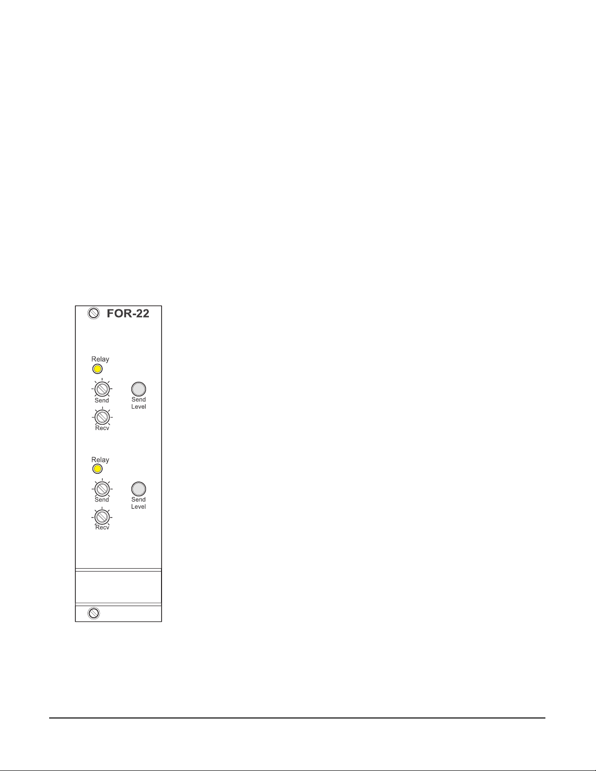
In normal use, the FOR-22 interface does not require operator
interaction. Each channel features the same set of front panel
controls:
• A "send" level control
• A "receive" level control
• A "send level" LED
• A "relay active" LED
"SEND" CONTROLS
The "send" controls affect the level of t he signals from the matrix to the
external devices. This control should be adjusted so that the "send
level" LED (see below) lights green when a signal is present.
Occasional red flashes due to peaks in the audio signal are
acceptable. The "send" controls have a range of ± 10 dB.
"SEND LEVEL" LEDS
The 2-color "send level" LED lights green when the audio signal is
being sent to the external device at a typical acceptable level. The LED
lights red when the audio output signal level is too high.
"RECV" CONTROLS
The "recv" ("receive") level controls affect the level of the signals sent
from the external devices to the matrix. The "recv" controls have a
range of ± 10 dB.
RELAY ACTIVE LED
The amber "relay" LED lights whenever the relay is activated.
1-2
FOR-22 Dual 4-Wire Interface Instruction Manual
Vitec Group Communications
Page 9

INSTALLING THE
2
FOR-22 INTERFACE
This chapter includes the following topics about installing the FOR-22
interface:
• Overview of interface frames and power supplies.
• Installing the interface in an interface frame.
• Wiring the interface to the matrix and to external devices.
• Adjusting the interface’s front-panel controls after installation.
INTERFACE FRAMES AND POWER SUPPLIES
Interface modules convert the 4-wire signals of a central matrix port to
some other form of communication, such as for telephones, camera
intercoms, two-way radios, and so on.
Each interface module connects to both the central matrix and to the
external device through cable attached to hardware connectors on the
rear of the interface module. To house these interface modules,
Clear-Com offers various types of interface frames. The two interface
frames which can house the FOR-22 dual 4-wire/radio interface are
the IMF-3 and the IMF-102 frames, which are described below.
IMF-3 Interface Module Frame
The IMF-3 interface frame holds up to 11 interface modules in three
rack units (3 RU) of a standard Electronics Industry Association
19-inch wide (48.26 cm) rack. The frame holds a modular,
rear-mounted connector panel for each interface, containing two RJ-45
connectors for connecting cable to matrix ports, and two DB-9
connectors for connecting cable to external devices. Figure 2-1
illustrates the rear panel of an IMF-3 interface frame, with 11
rear-panel assemblies installed.
The frame uses an external PSU-101 rack-mounted power supply to
supply power to the interface modules. A second PSU-101 can be
attached for redundancy.
As a rule-of-thumb, one PSU-101 power supply unit is required for
every two IMF-3 frames. A PSU-101 power supply unit requires 90 to
260 VAC at 45 to 65 Hz with a maximum dissipation of 80 watts. A
PSU-101 connected for redundancy requires very little current unless
used.
Vitec Group Communications
FOR-22 Dual 4-Wire Interface Instruction Manual
2-1
Page 10

For more information on the IMF-3 frame, refer to its manual in the
Eclipse manual set.
CH. A
Matrix
PHONE
LINE A
CH. B
Matrix
PHONE
LINE B
CH. A
CH. A
Matrix
CH. A
CH. A
I/O
I/O
PHONE
LINE A
CH. B
Matrix
CH. B
CH. B
I/O
I/O
PHONE
LINE B
Matrix
PHONE
LINE A
CH. B
Matrix
PHONE
LINE B
Matrix
CH. A
CH. A
I/O
I/O
PHONE
LINE A
CH. B
Matrix
CH. B
CH. B
I/O
I/O
PHONE
LINE B
CH. A
CH. A
Matrix
PHONE
LINE A
CH. B
Matrix
PHONE
LINE B
CH. A
Matrix
CH. A
CH. A
I/O
I/O
PHONE
LINE A
CH. B
Matrix
CH. B
CH. B
I/O
I/O
PHONE
LINE B
CH. A
Matrix
PHONE
LINE A
CH. B
Matrix
PHONE
LINE B
CH. A
CH. A
Matrix
PHONE
LINE A
CH. B
Matrix
PHONE
LINE B
CH. A
Matrix
CH. A
CH. A
I/O
I/O
PHONE
LINE A
CH. B
Matrix
CH.
B
CH. B
I/O
I/O
PHONE
LINE B
Matrix
CH. A
CH. A
I/O
I/O
PHONE
LINE A
CH. B
Matrix
CH. B
CH. B
I/O
I/O
PHONE
LINE B
CH. A
Matrix
PHONE
LINE A
CH. B
Matrix
PHONE
LINE B
POWER SUPPLY #1
CH. A
I/O
POWER SUPPLY #2
CH. B
I/O
Figure 2-1: IMF-3 Interface Frame Rear Panel
Note: The IMF-3 frame has an individual rear panel for each
interface. All interfaces use the same rear panel; however
the use of the rear-panel connectors will vary with the type
of interface.
Each interface features indicators and controls that must be accessible
to operators, so put the interface module frame(s) in a convenient
location. Usually interface module frames are located near the matrix
frame, but they can be located farther away. The maximum distance
between the matrix frame and the interface frame is 500 feet (150
meters).
Each Eclipse frame contains its own power supplies and does not
supply any power for interfaces. A separate power supply (PSU-101) is
only necessary for interfaces mounted in IMF-3 frames. If redundant
power supply pairs are used for interfaces, mount them together.
2-2
It is required that you leave an extra rack unit (1.75 in. or 44.45 mm)
above and below each external power supply unit. This allows for
needed cooling for larger system loads.
IMF-102 Interface Module Frame
The IMF-102 interface frame has slots for two interface modules in one
rack unit (1 RU) of a standard Electronics Industry Association 19-inch
wide (48.26 cm) rack.
It has an internal power supply and a connector for a redundant power
supply. The IMF-102 requires 90 to 250 VAC with a maximum
dissipation of 20 watts.
Its rear input/output connector panel has two RJ-45 connectors and
two DB-9 connectors for the two interface modules. Figure 2-2
illustrates the rear panel of an IMF-102 interface frame, with two
installed rear-panel assemblies.
FOR-22 Dual 4-Wire Interface Instruction Manual
Vitec Group Communications
Page 11

CH.A
CH.A
Marix
I/O
CH.B
CH.B
I/O
Matrix
CH.A
CH.A
Marix
I/O
CH.B
CH.B
I/O
Matrix
Figure 2-2: IMF-102 Interface Frame Rear Panel
For more information on the IMF-102 interface frame, refer to the
Interface Module Frames Instruction Manual in the Eclipse manual set
(part no. 810313Z).
INSTALLING THE FOR-22 IN AN INTERFACE FRAME
IMF-3 INTERFACE FRAME
This section describes how to install an FOR-22 unit in an IMF-3
frame. There are certain options available on the FOR-22 that can be
changed before installation. The audio output level can be set to
different ranges depending on the type of input is being driven. The
input of a channel can have a bridged pad added to allow higher input
levels.
To install the FOR-22 interface module in the IMF-3 interface frame:
1. Select a slot to install the interface in.
2. Remove the blank plate covering the slot.
3. Set any necessary Audio Output Level Jumpers.
4. Set any necessary Audio Input Level modifications.
5. Slide the FOR-22 in the slot and ensure that the card is fully seated.
6. Tighten the FOR-22's front panel mounting screws.
IMF-102 INTERFACE FRAME
The IMF-102 interface frame contains two slot s for installing interfaces.
Interfaces are installed horizontally in one rack unit (1 RU) of a
standard Electronics Industry Association equipment rack.
You install the FOR-22 interface in an IMF-102 interface frame as you
would install an interface in an IMF-3 interface frame.
AUDIO OUTPUT LEVEL JUMPER
The audio output is transformer isolated. There is a jumper field for
each channel that allows three basic operating levels depending on
what type of external input is being driven. The following levels can be
produced by each channel:
Vitec Group Communications
FOR-22 Dual 4-Wire Interface Instruction Manual
• Line level ------------------------- 0.0 dBu at 600 ohms
• Clear-Com IFB level ------------ -15 dBu at 200 ohms
2-3
Page 12

• Microphone level ----------------- -55.0 dBu at 20 ohms
To set channel 1 for the desired level:
1. Find jumper block JP100 on the circuit board.
2. Move the jumper so that it connects the pair of jumper pins labeled
with the desired level (Line, IFB, or Mic).
To set channel 2, repeat the above procedure using JP200.
Each FOR-22 channel can also be adjusted using its "Send" front
panel control.
See Figure 3-1 in Chapter 3 for a diagram of the FOR-22 main PCB
showing the location of the jumpers.
AUDIO INPUT LEVEL GREATER THAN +10 DBU
To accommodate input levels greater than +10 dBu on either channel,
the FOR-22 circuit board can be modified to build bridging pads on the
primary side of each channel's input transformer. To build a bridging
pad:
1. Find the jumpers labeled R111 and R112 (for channel 1) or R211
and R212 (for channel 2). These jumpers are located under the
"Level Detect" daughterboard; it may be necessary to disassemble
the FOR-22 module to access them. The jumpers look like 1/4 watt
resistors with a single black band (indicating "0 ohms").
2. Replace the jumpers with resistors according to the values shown in
Table 2-1.
3. Install R113 (for channel 1) or R213 (for channel 2) according to the
values shown in Table 2-1.
2-4
Attenuation
(dBu)
15
20
25
30
R111/R211
(Ohm)
470
1k
1k
1.2k
R112/R212
(Ohm)
470
1k
1k
1.2k
R113/R213
(Ohm)
1.2k
1k
470
470
Table 2-1: Resistor Values for Audio Input Bridging Pads
See Figure 3-1 in Chapter 3 for a diagram of the FOR-22 main PCB
showing the location of the jumpers.
FOR-22 Dual 4-Wire Interface Instruction Manual
Vitec Group Communications
Page 13

WIRING
A
The FOR-22 interface connects to an Eclipse matrix through the two
RJ-45 connectors on the IMF-3 or IMF-102 rear-panel assembly to
which the FOR-22 unit is connected. One RJ-45 connector is for the
first channel of the interface. The second RJ-45 connector is for the
second channel. Figure 2-3 shows pin assignments of the RJ-45
connectors used to connect the interface to an Eclipse matrix.
Interface Wiring
Matrix Frame End
Interface End
Call Receive +
Call Receive -
udio Receive +
Audio Send +
Audio Send -
Audio Receive -
Call Send +
Call Send -
1
2
3
4
5
6
7
8
ATT-T568B (Modular Jumpers Wired One to One)
1 2 3 4 5 6 7 8
Pair 2
Pair 1
Pair 3
Pair 4
Rear View of
Connector
Call Send +
1
Call Send -
2
Audio Send +
3
Audio Receive +
4
Audio Receive -
5
Audio Send -
6
Call Receive +
7
Call Receive -
8
Figure 2-3: Matrix to Interface Frame Wiring
The "user" side of the FOR-22 for each channel is on a DB-9M
connector on the rear of the IMF-3 or IMF-102 frame. Figure 2-4 shows
the pinout of either one of these connectors. Each channel is identical.
The following sections describe how to wire for the various type of
inputs and outputs available on this connector:
• External Audio Devices
• Call Signal Input
• Relay Contacts
Vitec Group Communications
FOR-22 Dual 4-Wire Interface Instruction Manual
2-5
Page 14

FOR-22 I/O DB-9M
1
6
2
7
3
8
4
9
5
Audio Output
Audio Output
Audio Input
Audio Input
Logic Input (+/- 4 to 50 V)
Logic Input (+/- 4 to 50 V)
Relay Normally Closed
Relay Wiper
Relay Normally Open
Figure 2-4: Pinout of the DB-9M I/O Connectors for FOR-22s
EXTERNAL AUDIO DEVICES
Connect external audio devices to the FOR-22 ports through the two
DB-9M connectors labeled "I/O" on the rear panel assembly panel.
Both audio input and output are transformer isolated. Refer to Figure
2-4 for pinouts.
CALL SIGNAL INPUT
The Call Signal input is used to receive a "call signal" or logic input
from an external device and send it to the matrix. The voltage across
the pins required to receive a call signal ranges from 4 Volts to 50
volts; it can be either positive or negative polarity or AC. The input will
draw between 4 and 8 milliamps. Refer to Figure 2-4 for pinouts.
RELAY CONTACTS
Each FOR-22 channel features a relay that is associated with the
logical "call signal" output of a port. A relay's function depends on the
function assigned to the FOR-22 port in the configuration software. A
relay can be assigned to operate with any label in the system: when
that label is activated (either by a talk, listen, or both as set from the
configuration program), the relay will be activated. Or it can be
assigned to be activated by a call signal, for example to operate a
2-way radio transmitter.
You can use the relay to activate an external device, such as an
applause light in a studio, a cue light, or a security door lock. The
relays feature both "normally open" and "normally closed" contacts.
The contacts are rated at 1 Amp at 24 volts DC; they are not designed
for switching mains AC line voltage. Refer to Figure 2-4 for pinouts.
2-6
FOR-22 Dual 4-Wire Interface Instruction Manual
Vitec Group Communications
Page 15

ADJUSTMENTS
After installation the front-panel controls should be set to
accommodate the normal range of input and output levels
encountered. The following is a discussion of the controls and
indicators on the front of the interface.
"Send Level" Control
The "send level" control allows adjustment of the output level of the
channel from the matrix to the external device/system.
"Send Level" LED
The 2-color "send level" LED lights green when an audio signal is
being sent to the external device or system at a typical acceptable
level. The LED lights red when the audio output signal level is too hig h.
"Recv" Control
The "recv" ("receive") level controls affect the level of signals sent from
external devices or system to the matrix. The "recv" controls have a
range of ± 10 dB.
Relay Active LED
The yellow "relay" LED lights whenever the relay is activated.
Intermittent fast blinking on this LED is normal.
CONFIGURATION
You configure a central matrix port to work with the FOR-22 interface
by setting parameters in the Eclipse Configuration System (ECS)
programming software. Refer to the Eclipse Configuration System
Instruction Manual for more information.
Vitec Group Communications
FOR-22 Dual 4-Wire Interface Instruction Manual
2-7
Page 16

2-8
FOR-22 Dual 4-Wire Interface Instruction Manual
Vitec Group Communications
Page 17

3
MAINTENANCE
This chapter provides schematics, assembly drawings, and
component lists for the FOR-22 dual 4-wire interface module.
FOR-22 MAIN PCB
Vitec Group Communications
FOR-22 Dual 4-Wire Interface Instruction Manual
Figure 3-1: FOR-22 Main Board PCB (Part No. 710572)
3-1
Page 18

BILL OF MATERIALS FOR FOR-22 MODULE PCB
Designator Component Description Qty
C103,C105,C107,C110,C115,
C119,C203,C205,C207,C210,
C215,C219
C104,C106,C111,C114,C117,
C118,C204,C206,C211,C214,
C217,C218
C101,C102,C109,C201,C202,
C209
C113,C112 22UF ALU 50V 20% SM D 8X6M M 2
FOR-22 MAIN SMT PCB FAB 1
J1 EURO CARD RT ANG CONN 64
JP100,JP200 JUMP JACK .1IN WITH HAN D LE 2
J2 7 PIN DUAL ROW SOCKET
JP200,JP100 DUAL RO W HEADER 3 PO S
P101,P102,P201,P202 PIHER TRIMPOT SHAFT #5116
J1(2) RIVET AVDEL #1189-2510 2
LED101,LED201 T1 RT ANG PC M TG 5m A AM B ER
R110,R122,R123,R210 10.0 1/10W 1% SMD 0805 4
R118,R119,R218,R219 56.2 1/10W 1% SMD 0805 4
R125,R225 82.5 1/10W 1% SMD 0805 2
R115,R215 100 1/10W 1% SMD 0805 2
R229,R129 150 1/10W 1% SMD 0805 2
R109,R209 221 1/10W 1% SMD 0805 2
R130,R230 1.00K 1/10W 1% SMD 0805 2
R208,R108 2.74K 1/10W 1% SMD 0805 2
R120,R121,R124,R220,R221,
R224
R105,R106,R114,R116,R117,
R126,R127,R131,R132,R205,
R206,R214,R216,R217,R226,
R227,R231,R232
R101,R102,R103,R104,R201,
R202,R203,R204
R228,R128 47.5K 1/10W 1% SMD 0805 2
RL101,RL201 SPDT 12V MINI PC RELAY
P101,P102,P201,P202 50K TRIMPOT PIHER#PT10WHD201,D101 BAV70 DUAL DIODE COMMO N
D103,D104,D203,D204 BAW56 DU AL D IODE C OM M O N
IC101,IC102,IC104,IC201,
IC202,IC2 04
Q101,Q103,Q201,Q203 PMBT 2222A NP N 40V 600MA
IC203,IC103 M0C211 OPTOCOUPLER... S0 IC8 2
33PF 50V 5% NPO SM D 0805 12
.1UF 50V 10% X7R SM D 0805 12
.22UF 50V 10% X7R SM D 1210 6
1
PIN M
1
SPECIAL
2
.230IN
4
BLAC
2
LED
4.75K 1/10W 1% SMD 0805 6
10.0K 1/10W 1% SMD 0805 18
27.4K 1/10W 1% SMD 0805 8
2
ITT#SZ1
4
50K
2
CATHOD
4
ANODE.
833 DUAL OPAM P... SOIC8 6
4
SOT-23
3-2
FOR-22 Dual 4-Wire Interface Instruction Manual
Vitec Group Communications
Page 19

SCHEMATIC FOR FOR-22 MODULE PCB
C119
12
12
33 pF
1A1C2A2C3A3C4A4C5A5C6A6C7A7C8A8C9A9C10A
J1
Q202
MMBT5551
12
312
R118
56.2
MATRIX
TO
CHANNEL
1 2
R117
10.0K
C115 33 pF
1 2
C111
.1 uF
12
R115
100
1 2
+8V
RECEIVE
0
R112
0
R111
R132
10.0K
1 2
1 2
+8V
R131
10.0K
1 2
R106
10.0K
1 2
C105
33 pF
+8V
C110
33 pF
1 2
2
P102
50K
13
CCW
JP100
R108
2.74K
12
C117
.1 uF
12
13
1 2
12
C104
.1 uF
MATRIX SEND
FROM
CHANNEL
246
+++
+++
135
P101
CCW
1 2
A
CW
R114
MICCWLINE
IFB
84
2
50K
R104
R101
C101
84
2
10.0K
1 2
LEVEL SELECT JUMPER
R109
12
1
-
2
CW
27.4K
84
2
27.4K
1 2
.22 uF
1 2
R116
IC102A
LM833 SOIC
1
+
-
3
C109
.22 uF
12
534
T102
1
2
12
*
R113
221
R110
12
T101
..
2 11
IC104A
LM833
C118
1 2
+
3
C107
33 pF
1 2
R105
10.0K
1 2
IC101A
LM833
1
+
-
3
C103
12
R103
27.4K
R102
27.4K
1 2
C102
.22 uF
1 2
3
R119
56.2
A
1 2
7
IC102B
1 2
+
-
5
6
1 2
10.0K
12
C114
.1 uF
6
AUDIO 10K : 10K
* R113
NOT
LOADED
10.0
AUDIO 600 : 600
5 8
.1 uF
-8V
7
IC101B
LM833
+
-
5
6
C106
.1 uF
12
33 pF
1 2
1 2
D201 BAV70
R224
4.75K
LM833
-8V
Q102
MMBT5551
12
312
3
1 2
D101 BAV 70
R124
4.75K
+8V
12
7
IC104B
LM833
+
-
5
6
-8V
R225
12
R125
12
R128
47.5K
10C
11A
11C
12A
12C
13A
13C
14A
14C
15A
15C
16A
16C
17A
17C
18A
18C
19A
19C
20A
20C
21A
21C
22A
22C
23A
23C
24A
24C
25A
+8V
12
R122
10.0
CALL
RECEIVE
TO
MATRIX
Q203
MMBT2222A
312
R226
10.0K
1 2
5 6
7
IC203
MOC211
82.5
3
12
1 2
D203
BAW56
1 2
3
D202
BAV99
FOR CALL LOGIC
RECEIVE
4-50VDC EITHER
POLARITY
4-8mA
CALL
RECEIVE
TO
MATRIX
CH. A CH. B
Q103
MMBT2222A
312
R126
10.0K
1 2
5 6
7
82.5
IC103
MOC211
3
1 2
12
D103
BAW56
3
D102
1 2
BAV99
4-50VDC EITHER
POLARITYTOFOR CALL LOGIC
RECEIVE
4-8mA
TO LEVEL
DETECT
PCB
-8V
LED101
AMBER
21
3
D104
BAW56
1 2
2
5
RL101
R120
4.75K
R129
150
1 2
1 2
Q104
MMBTA56
R127
10.0K
Q101
MMBT2222A
312
1 2
R121
4.75K
R130
1.00k
1 2
SEND
CALL
CH. A
12
R123
10.0
C113
22uF
35V
+
+
C112
22uF
35V
12
12
2 1
2 1
D2
GF1A
D1
GF1A
2468101214
+++++++
+++++++
J2
13579
11
13
1
4
3
+8V
12
1 2
EURO 64 M
25C
26A
26C
27A
27C
28A
28C
29A
30A
30C
31A
31C
32A
32C
29C
-8V
R219
56.2
R218
56.2
1 2
1 2
MATRIX
CHANNEL
B
7
IC202B
LM833
R217
10.0K
1 2
+
-
C215 33 pF
1 2
5
CW
12
T201
C207
33 pF
R205
IC201A
+
3
1 2
.22 uF
1 2
R214
R210
2 11
C218
1 2
10.0K
LM833
10.0K
10.0
..
R202
84
-
2
1 2
.1 uF
1 2
-
6
C203
12
R203
27.4K
27.4K
1
3
12
5 8
-8V
7
5
33 pF
IC202A
LM833
+
C209
.22 uF
T202
12
AUDIO 600 : 600
IC201B
LM833
+
C206
12
1 2
6
1 2
R216
10.0K
-8V
12
C214
.1 uF
6
534
1
2
AUDIO 10K : 10K
*R213
NOT
LOADED
*
R213
7
IC204B
LM833
+
-
5
6
.1 uF
-8V
C211
.1 uF
12
R215
100
C210
33 pF
1 2
1 2
+8V
2
P202
50K
13
CCW
RECEIVE
0
R212
12
12
0
R211
-8V
LED201
AMBER
21
3
D204
BAW56
1 2
1
2
5
RL201
R220
4.75K
R229
150
1 2
1 2
Q204
MMBTA56
R228
47.5K
R227
10.0K
Q201
MMBT2222A
312
1 2
R221
4.75K
R230
1.00k
1 2
SEND
CALL
CH. B
IFB
MIC
LINE
4
3
246
+++
+++
JP200
LEVEL SELECT JUMPER
135
R208
2.74K
R209
221
12
12
1 2
C217
.1 uF
12
IC204A
LM833
1
84
+
-
+8V
C219
33 pF
R232
10.0K
1 2
3
2
1 2
R231
10.0K
1 2
R206
10.0K
1 2
2
P201
50K
13
CCW
SEND
1 2
1
C205
33 pF
R204
27.4K
1 2
1 2
84
+8V
-
2
12
C204
.1 uF
R201
27.4K
1 2
FROM
CHANNEL
B
C202
C201
.22 uF
MATRIX
1 2
Figure 3-2: Schematic for FOR-22 Main Board PCB (Part No. 710572)
Vitec Group Communications
FOR-22 Dual 4-Wire Interface Instruction Manual
3-3
Page 20

ASSEMBLY DRAWING FOR FOR-22 LEVEL DETECT PCB
3-4
Figure 3-3: Assembly Drawing for FOR-22 Level Detect PCB (Part No.
710571)
FOR-22 Dual 4-Wire Interface Instruction Manual
Vitec Group Communications
Page 21

BILL OF MATERIALS FOR FOR-22 LEVEL DETECT PCB
Designator Component Description Qty Per
C5,C6,C7,C8 .1UF 50V 10% X7R SMD 0805 4
C4,C2 .22UF 50V 10% X7R SMD 1210 2
C1,C3 .47UF TAN 35V 10% SMT A 2
FOR-22 LED SMT PCB FAB 1
P1 DUAL ROW HEADER 7 POS. .320IN 1
LED2,LED1 BI-COLOR RED/GREEN 3 LEAD 2
R9,R8 475 1/10W 1% SMD 0805 2
R2,R5 23.7K 1/10W 1% SMD 0805 2
R1,R4,R7 47.5K 1/10W 1% SMD 0805 3
R3,R6 332K 1/10W 1% SMD 0805 2
VR2,VR1 100K TRIM POT V.ADJ PIHER#10V1 2
IC1 833 DUAL OPAMP... SOIC8 1
D1,D2,D3,D4,D5,D6,D7,D8 BAV99 DUAL DIODE... SOT23 8
IC2,IC3 358 DUAL OPAMP GROUND
SENSING.
2
Vitec Group Communications
FOR-22 Dual 4-Wire Interface Instruction Manual
3-5
Page 22

SCHEMATIC FOR LEVEL DETECT PCB
C7
.1uF
1
IC2A
84
+
-
3
2
R7
47.5K
D1
BAV99
3
12
THRESHOLD
LM358
R2
VR1
23.7K
31
100K
1
3
3
1 2
7
IC2B
+
-
5
6
3
12
D5
BAV99
D2
BAV99
C5
.1uF
1
84
-
3
2
2
IC3B
LED2
1
R
G
3
D8
BAV99
LM358
R6
C4
D4
BAV99
3
1 2
7
IC1B
LM833
+
-
5
6
332K
.22uF
R9
475
2
LEVEL DETECT PCB
ASY 710571
LED1
R
G
D7
BAV99
LM358
R3
C2
3
1 2
IC1A
LM833
+
332K
.22uF
R8
475
2
3
C8
C6
.1uF
.1uF
84
-
2
12
1
D3
+
3
BAV99
IC3A
LM358
3
-
6
3
12
D6
23.7K
R5
31
THRESHOLD
VR2
100K
1 2
7
BAV99
2
+
5
3-6
47.5K
R1
C1
.47uF
2468101214
+++++++
+++++++
P1
13579
11
13
47.5K
R4
C3
.47uF
Figure 3-4: Schematic for Level Detect PCB (Part No. 710571)
FOR-22 Dual 4-Wire Interface Instruction Manual
Vitec Group Communications
Page 23

4
SPECIFICATIONS
Note: 0 dBu is Referenced to 0.775 Volts RMS
Audio Output
Nominal Output Level Selectable by Jumper Between 0 dBu
-15 dBu, or -55 dBu
Impedance 600 ohms at 0 dBu
200 ohms at -15 dBu
20 ohms at -55 dBu
Frequency Response 200-10k Hz, ±3 dB
Maximum Output Level +20 dBu
Audio Input
Level 0 dBu nominal
Impedance >10K ohms (bridging)
Frequency Response 200-10k Hz, ±3 dB
Call Signal Input
Threshold 4 volts DC, Positive or Negative
Polarity
Maximum Input Voltage 50 volts
Relay Contacts
Contact Type 1 pair SPDT (single form C)
Contact Voltage Rating 24 volts DC
Contact Current Rating 1 A continuous, 2 A peak at 24 volts
DC
DC Isolation
Greater than 10 mega-ohms.
Power Supply
Supplied by PSU-101 power supply
Voltage Required ± 8 volts DC Unregulated
Current Required 30 milliamps (per supply, no LEDs or
relays active)
160 milliamps (positive supply, LEDs
and relays active)
140 milliamps (negative supply, all
LEDs and relays active)
Connectors (on rear of IMF-3 frame)
RJ-45 "To Matrix" Connectors 2
DB-9M "Interface I/O" Connectors2
Vitec Group Communications
FOR-22 Dual 4-Wire Interface Instruction Manual
4-1
Page 24

Operating Environment
Temperature Between 0ºC and 70°C (32ºF -150°F)
Package Dimensions
Frame Slot Usage 1 slot of IMF-3 or IMF-102 frame
Weight 0.54 lb (0.22 kg)
Notice About Specifications
While Vitec Group Communications makes every attempt to maintain
the accuracy of the information contained in its product manuals, that
information is subject to change without notice. Performance
specifications included in this manual are design-center specifications
and are included for customer guidance and to facilitate system
installation. Actual operating performance may vary.
4-2
FOR-22 Dual 4-Wire Interface Instruction Manual
Vitec Group Communications
Page 25

LIMITED WARRANTY
Vitec Group Communications (VGC) warrants that at the time of
purchase, the equipment supplied complies with any specification in
the order confirmation when used under normal conditions, and is free
from defects in workmanship and materials during the warranty period.
During the warranty period VGC, or any service company authorized
by VGC, will in a commercially reasonable time remedy defects in
materials, design, and workmanship free of charge by repairing, or
should VGC in its discretion deem it necessary, replacing the product
in accordance with this limited warranty. In no event will VGC be
responsible for incidental, consequential, or special loss or damage,
however caused.
WARRANTY PERIOD
Return Material Authorization
(RMA) numbers are required
for all returns.
Both warranty and
non-warranty repairs are
available.
The product may consist of several parts, each covered by a different
warranty period. The warranty periods are:
• Cables, accessories, components, and consumable items have a
limited warranty of 90 days.
• Headsets, handsets, microphones, and spare parts have a limited
warranty of one year.
• UHF wireless IFB products have a limited warranty of one year.
• UHF wireless intercom systems have a limited warranty of three
years.
• All other Clear-Com and Drake brand systems and products,
including beltpacks, have a limited warranty of two years.
The warranty starts at the time of the product’s original purchase. The
warranty start date for contracts which include installation and
commissioning will commence from the earlier of date of the Site
Acceptance Test or three months from purchase.
TECHNICAL SUPPORT
To ensure complete and timely support to its customers, VGC’s User
Support Center is staffed by qualified technical personnel. Telephone
and email technical support is offered worldwide by the User Support
Center.
Vitec Group Communications
Warranty
The User Support Center is available to VGC’s customers during the
full course of their warranty period.
Instructions for reaching VGC’s User Support Centers are given below.
i
Page 26

T elephone for Europe, Middle East and Africa: +49 40 6688 4040 or
+44 1223 815000
Telephone for the Americas and Asia: +1 510 337 6600
Email: vitec.support@AVC.de
Once the standard warranty period has expired, the User Support
Center will continue to provide telephone support if you have
purchased an Extended Warranty.
For latest contact information please refer to the Service and Support
section at www.clearcom.com.
WARRANTY REPAIRS AND RETURNS
Before returning equipment for repair, contact a User Support Center
to obtain a Return Material Authorization (RMA). VGC representatives
will give you instructions and addresses for returning your equipment.
You must ship the equipment at your expense, and the support center
will return the equipment at VGC’s expense.
For out-of-box failures, use the following contact information:
Europe, Middle East and Africa
Tel: +44 1223 815000 Email: SalesSupportEMEA@vitecgroup.com
North America, Canada, Mexico, Caribbean & US Military
Tel: +1 510 337 6600 Email: SalesSupportUSA@vitecgroup.com
Asia Pacific & South America
Tel: +1 510 337 6600 Email: SalesSupportAPAC@vitecgroup.com
VGC has the right to inspect the equipment and/or installation or
relevant packaging.
For latest contact information please refer to the Service and Support
section at www.clearcom.com.
NON-WARRANTY REPAIRS AND RETURNS
For items not under warranty, you must obtain an RMA by contacting
the User Support Center. VGC representatives will give you
instructions and addresses for returning your equipment.
You must pay all charges to have the equipment shipped to the
support center and returned to you, in addition to the costs of the
repair.
EXTENDED WARRANTY
You can purchase an extended warranty at the time of purchase or at
any time during the first two years of ownership of the product. The
ii
Vitec Group Communications
Warranty
Page 27

purchase of an extended warranty extends to five years the warranty
of any product offered with a standard two-year warranty. The total
warranty period will not extend beyond five years.
Note: VGC does not offer warranty extensions on UHF wireless
intercom systems, or on any product with a 1-year or 90-day warranty.
LIABILITY
THE FOREGOING WARRANTY IS VGC'S SOLE AND EXCLUSIVE
WARRANTY. THE IMPLIED WARRANTY OF MERCHANTABILITY
AND FITNESS FOR A PARTICULAR PURPOSE AND ANY OTHER
REQUIRED IMPLIED WARRANTY SHALL EXPIRE AT THE END OF
THE WARRANTY PERIOD. THERE ARE NO OTHER WARRANTIES
(INCLUDING WITHOUT LIMITATION WARRANTIES FOR
CONSUMABLES AND OTHER SUPPLIES) OF ANY NATURE
WHATSOEVER, WHETHER ARISING IN CONTRACT, TORT,
NEGLIGENCE OF ANY DEGREE, STRICT LIABILITY OR
OTHERWISE, WITH RESPECT TO THE PRODUCTS OR ANY P ART
THEREOF DELIVERED HEREUNDER, OR FOR ANY DAMAGES
AND/OR LOSSES (INCLUDING LOSS OF USE, REVENUE, AND/OR
PROFITS). SOME STATES DO NOT ALLOW THE EXCLUSION OR
LIMITA TION OF INCIDENTAL OR CONSEQUENTIAL DAMAGES OR
THE LIMIT ATION ON HOW LONG AN IMPLIED WARRANTY LASTS,
SO THE ABOVE LIMITATIONS MAY NOT APPLY TO YOU. IN ANY
EVENT, TO THE MAXIMUM EXTENT PERMITTED UNDER
APPLICABLE LAW , VGC'S LIABILITY T O CUSTOMER HEREUNDER
SHALL NOT UNDER ANY CIRCUMSTANCES EXCEED THE COST
OF REPAIRING OR REPLACING ANY PART(S) FOUND TO BE
DEFECTIVE WITHIN THE WARRANTY PERIOD AS AFORESAID.
Vitec Group Communications
Warranty
This warranty does not cover any damage to a product resulting from
cause other than part defect and malfunction. The VGC warranty does
not cover any defect, malfunction, or failure caused beyond the control
of VGC, including unreasonable or negligent operation, abuse,
accident, failure to follow instructions in the manual, defective or
improperly associated equipment, attempts at modification and repair
not approved by VGC, and shipping damage. Products with their serial
numbers removed or defaced are not covered by this warranty.
This warranty does not include defects arising from installation (when
not performed by VGC), lightning, power outages and fluctuations, air
conditioning failure, improper integration with non-approved
components, defects or failures of customer furnished components
resulting in damage to VGC provided product.
This limited warranty is not transferable and cannot be enforced by
anyone other than the original consumer purchaser.
This warranty gives you specific legal rights and you may have other
rights which vary from country to country.
iii
Page 28

iv
Vitec Group Communications
Warranty
 Loading...