

Page 1

ECLIPSE-32 MATRIX
INSTRUCTION MANUAL
Page 2

Eclipse-32 Matrix Instruction Manual
©2005 Vitec Group Communicatons, Inc.
All Rights Reserved
Part Number 810315 Rev. A
Vitec Group Communications, Inc.
4065 Hollis Street
Emeryville, CA 94608-3505
U.S.A
Clear-Com is a registered trademark of Vitec Group Communications, Inc.
The Clear-Com Logo is a registered trademark of Vitec Group Communications, Inc.
Matrix Plus is a registered trademark of Vitec Group Communications, Inc.
Eclipse is a registered trademark of Vitec Group Communications, Inc.
Windows is a registered trademark of Microsoft Corp.
Page 3

CONTENTS
IMPORTANT SAFETY INSTRUCTIONS . . . . . . . . . . . . . . . . . . . . . . . . . . ii-iii
INTRODUCTION . . . . . . . . . . . . . . . . . . . . . . . . . . . . . . . . . . . . . 1-1
The Eclipse-32 Matrix. . . . . . . . . . . . . . . . . . . . . . . . . . . . . . . . . . . . . . . . . . 1-1
Intelligent Linking. . . . . . . . . . . . . . . . . . . . . . . . . . . . . . . . . . . . . . . . . . . 1-1
Powerful Programming Features . . . . . . . . . . . . . . . . . . . . . . . . . . . . . . . . 1-2
Individual Level Control . . . . . . . . . . . . . . . . . . . . . . . . . . . . . . . . . . . . . . 1-2
Excellent Audio Quality. . . . . . . . . . . . . . . . . . . . . . . . . . . . . . . . . . . . . . . 1-3
Robust and Compatible. . . . . . . . . . . . . . . . . . . . . . . . . . . . . . . . . . . . . . . 1-3
Eclipse-32 Applications . . . . . . . . . . . . . . . . . . . . . . . . . . . . . . . . . . . . . . . 1-3
System Basics. . . . . . . . . . . . . . . . . . . . . . . . . . . . . . . . . . . . . . . . . . . . . . . . . 1-3
Matrix Hardware. . . . . . . . . . . . . . . . . . . . . . . . . . . . . . . . . . . . . . . . . . . . 1-3
Power Supplies. . . . . . . . . . . . . . . . . . . . . . . . . . . . . . . . . . . . . . . . . . . . . . 1-4
Rear-Panel Connectors (“Ports”) . . . . . . . . . . . . . . . . . . . . . . . . . . . . . . . . 1-4
Eclipse Configuration Software (ECS). . . . . . . . . . . . . . . . . . . . . . . . . . . . 1-4
Remote Intercom Stations and Accessory Panels . . . . . . . . . . . . . . . . . . . . 1-5
Remote Interfaces . . . . . . . . . . . . . . . . . . . . . . . . . . . . . . . . . . . . . . . . . . . 1-5
OPERATING AN ECLIPSE-32 MATRIX . . . . . . . . . . . . . . . . . . . . . . . . . 2-1
Storing and Retrieving Configurations. . . . . . . . . . . . . . . . . . . . . . . . . . . . . . 2-1
Front-Panel Controls and Lights . . . . . . . . . . . . . . . . . . . . . . . . . . . . . . . . . . 2-1
PC Connector . . . . . . . . . . . . . . . . . . . . . . . . . . . . . . . . . . . . . . . . . . . . . . 2-1
Reset Button . . . . . . . . . . . . . . . . . . . . . . . . . . . . . . . . . . . . . . . . . . . . . . . 2-2
OK Light. . . . . . . . . . . . . . . . . . . . . . . . . . . . . . . . . . . . . . . . . . . . . . . . . . 2-2
Configuration “Config” Button. . . . . . . . . . . . . . . . . . . . . . . . . . . . . . . . . 2-2
Configuration Status Lights. . . . . . . . . . . . . . . . . . . . . . . . . . . . . . . . . . . . 2-2
Power Supply Alarm Lights (1 and 2) . . . . . . . . . . . . . . . . . . . . . . . . . . . . 2-2
LAN Status Lights . . . . . . . . . . . . . . . . . . . . . . . . . . . . . . . . . . . . . . . . . . . 2-3
Port Status Lights. . . . . . . . . . . . . . . . . . . . . . . . . . . . . . . . . . . . . . . . . . . . 2-3
Connecting the Matrix to Remote Devices . . . . . . . . . . . . . . . . . . . . . . . . . . 2-4
Connecting to AC Power. . . . . . . . . . . . . . . . . . . . . . . . . . . . . . . . . . . . 2-4
Connecting to Stations and Interfaces . . . . . . . . . . . . . . . . . . . . . . . . . . 2-4
Connecting to General-Purpose Outputs. . . . . . . . . . . . . . . . . . . . . . . . 2-5
Connecting to General-Purpose Inputs . . . . . . . . . . . . . . . . . . . . . . . . . 2-5
Connecting to a GPI/RLY Interface . . . . . . . . . . . . . . . . . . . . . . . . . . . 2-5
Connecting to a Second Eclipse Matrix . . . . . . . . . . . . . . . . . . . . . . . . . 2-6
Connecting to a Local Area Network. . . . . . . . . . . . . . . . . . . . . . . . . . . 2-6
INSTALLING AN ECLIPSE-32 MATRIX . . . . . . . . . . . . . . . . . . . . . . . . . 3-1
ECLIPSE-32 MATRIX INSTRUCTION MANUAL
Verifying the Shipment . . . . . . . . . . . . . . . . . . . . . . . . . . . . . . . . . . . . . . . . . 3-1
Unpacking the System. . . . . . . . . . . . . . . . . . . . . . . . . . . . . . . . . . . . . . . . . . 3-1
Installing the Eclipse-32 Matrix. . . . . . . . . . . . . . . . . . . . . . . . . . . . . . . . . . . 3-1
i
Page 4

INSTALLING AN ECLIPSE-32 MATRIX (CONTINUED)
Wiring the Matrix to Remote Devices . . . . . . . . . . . . . . . . . . . . . . . . . . . . . . 3-2
Wiring to AC Mains Power . . . . . . . . . . . . . . . . . . . . . . . . . . . . . . . . . . . . 3-2
Wiring to Stations and Interfaces. . . . . . . . . . . . . . . . . . . . . . . . . . . . . . . . 3-3
4-Pair Analog. . . . . . . . . . . . . . . . . . . . . . . . . . . . . . . . . . . . . . . . . . . . . 3-3
Single-Pair Digital . . . . . . . . . . . . . . . . . . . . . . . . . . . . . . . . . . . . . . . . . 3-4
Wiring General-Purpose Outputs . . . . . . . . . . . . . . . . . . . . . . . . . . . . . . . 3-4
Wiring General-Purpose Inputs . . . . . . . . . . . . . . . . . . . . . . . . . . . . . . . . . 3-5
Wiring to a GPI/RLY Interface . . . . . . . . . . . . . . . . . . . . . . . . . . . . . . . . . 3-9
RLY-6 Interface Wiring. . . . . . . . . . . . . . . . . . . . . . . . . . . . . . . . . . . . . 3-9
GPI-6 Interface Wiring . . . . . . . . . . . . . . . . . . . . . . . . . . . . . . . . . . . . 3-10
Wiring to a Second Eclipse Matrix. . . . . . . . . . . . . . . . . . . . . . . . . . . . . . 3-12
Wiring to a Local Area Network . . . . . . . . . . . . . . . . . . . . . . . . . . . . . . . 3-13
Wiring to a Computer. . . . . . . . . . . . . . . . . . . . . . . . . . . . . . . . . . . . . . . 3-14
MAINTAINING AN ECLIPSE-32 MATRIX . . . . . . . . . . . . . . . . . . . . . . . . 4-1
Recommended Spare Parts. . . . . . . . . . . . . . . . . . . . . . . . . . . . . . . . . . . . . 4-1
Dual, Independent Power Supplies . . . . . . . . . . . . . . . . . . . . . . . . . . . . . . 4-1
Technical Support . . . . . . . . . . . . . . . . . . . . . . . . . . . . . . . . . . . . . . . . . . . 4-1
SPECIFICATIONS. . . . . . . . . . . . . . . . . . . . . . . . . . . . . . . . . . . . . 5-1
GLOSSARY . . . . . . . . . . . . . . . . . . . . . . . . . . . . . . . . . . . . . . . . 6-1
VITEC GROUP COMMUNICATIONS WARRANTY. . . . . . . . . . . . . . . . . . . . . 7-1
ii
ECLIPSE-32 MATRIX INSTRUCTION MANUAL
Page 5

Please read and follow these
instructions before operating
an Eclipse-32 matrix
system.
IMPORTANT SAFETY INSTRUCTIONS
Please read and follow these instructions before operating an Eclipse-32 matrix
system. Keep these instructions for future reference.
(1) WAR NI NG : To reduce the risk of fire or electric shock, do not expose this
apparatus to rain or moisture.
(2) Do not use the apparatus near water.
(3) Clean only with a dry cloth.
(4) Do not block any ventilation openings. Install in accordance with the
manufacturer’s instructions. Install the Eclipse-32 matrix system according to the
directions in the Installation Chapter of this manual.
(5) Do not install near any heat sources such as radiators, heat registers, stoves, or
other apparatus (including amplifiers) that produce heat. Do not place naked
flame sources such as candles on or near the matrix.
(6) Do not defeat the safety purpose of the polarized plug or grounding-type
plug. A polarized plug has two blades with one wider than the other. A
grounding-type plug has two blades and a third grounding prong. The wide
blade or the third prong are provided for your safety. If the provided plug does
not fit into your outlet, consult an electrician for replacement of the obsolete
outlet.
(7) Protect power leads from being walked on or pinched particularly at plugs, at
convenience receptacles, and at the point where they exit from the apparatus.
Note: A “convenience receptacle” is an extra AC power outlet located on the back
of a piece of equipment, intended to allow you to power other equipment.
(8) Only use attachments/accessories specified by the manufacturer.
(9) Use only with the cart, stand, tripod, bracket, or table specified by the
manufacturer, or sold with the apparatus. When a cart is used, use caution when
moving the cart/apparatus combination to avoid injury from tip-over.
(10) Unplug the apparatus during lightning storms or when unused for long
periods of time.
(11) Refer all servicing to qualified service personnel. Servicing is required when
the apparatus has been damaged in any way, such as a power-supply cord or plug
is damaged, liquid has been spilled or objects have fallen into the apparatus, the
apparatus has been exposed to rain or moisture, does not operate normally, or has
been dropped.
(12) The Eclipse-32 matrix contains a non-user serviceable battery.
CAUTION: Danger of explosion if battery is incorrectly replaced. Replace only
with the same or equivalent type.
ECLIPSE-32 MATRIX INSTRUCTION MANUAL
iii
Page 6
Lithium batteries can overheat or explode if they are shorted. When you handle
the CPU card or a loose battery, DO NOT touch any external electrical
conductors to the battery’s terminals or to the circuits that the terminals are
connected to.
Please familiarize yourself with the safety symbols in Figure 1. When you see
these symbols on an Eclipse-32 matrix system, they warn you of the potential
danger of electric shock if the system is used improperly. They also refer you to
important operating and maintenance instructions in the manual.
CAUTION
RISK OF ELECTRIC SHOCK
DO NOT OPEN
This symbol alerts you to the presence of uninsulated dangerous
voltage within the product’s enclosure that might be of sufficient
magnitude to constitute a risk of electric shock. Do not open
the product’s case.
This symbol informs you that important operating and maintenance instructions are included in the literature accompanying
this product.
Figure 1: Safety Symbols
EMC AND SAFETY
The Eclipse-32 matrix meets all relevant CE, FCC, UL, and CSA specifications
set out below:
EN55103-1 Electromagnetic compatibility. Product family standard for audio,
video, audio-visual, and entertainment lighting control apparatus for professional
use. Part 1: Emissions.
EN55103-2 Electromagnetic compatibility. Product family standard for audio,
video, audio-visual, and entertainment lighting control apparatus for professional
use. Part 2: Immunity.
BS EN 60065:2002 Audio, video, and similar electronic apparatus. Safety
requirements.
And thereby compliance with the requirement of Electromagnetic Compatibility
Directive 89/336/EEC and Low Voltage Directive 73/23/EEC as amended by
93/68/EEC.
iv
ECLIPSE-32 MATRIX INSTRUCTION MANUAL
Page 7

1
The Eclipse-32 digital matrix
intercom features 32
full-duplex communications
ports, plus four 4-wire ports.
The matrix fits in one rack
unit (1 RU) of a standard
Electronic Industry
Association equipment rack.
INTRODUCTION
THE ECLIPSE-32 MATRIX
The Eclipse family of communications products now includes the Eclipse-32
digital matrix intercom, which offers 32 full-duplex communication ports, plus
four extra 4-wire ports, in a one rack unit (1 RU) chassis. The Eclipse-32 matrix
supports the same i-stations, 4000 series stations, ICS digital matrix stations and
interfaces as its larger counterpart, the Eclipse-208 matrix, and is programmed
and controlled with the same Eclipse Configuration System software.
You can join two Eclipse-32 matrices together to form an intelligently linked
non-blocking 64-port system in two rack units (2 RU) using a single RJ-45 “base
loop” connection. The matrix also provides two power supplies for fail-safe
redundancy, and onboard general-purpose inputs and outputs.
The Eclipse-32 matrix is built around the powerful Motorola 8260 processor,
giving it the same processing power as the larger Eclipse-208 matrix.
Features of the Eclipse-32 matrix include:
• Thirty-six ports in one rack unit (1 RU), including four 4-wire ports
• Eight onboard relays and eight onboard GPIs
• Non-blocking 64-port system created by connecting two matrices with the
high-speed link
• Intelligent linking of up to 15 matrices using the 4-wire trunks and a LAN
• Two power supplies for fail-safe redundancy
• Seamless interfacing
• DTMF inward access
• Programmable VOX
• Individual level control
• Intuitive ECS programming software
• Remote matrix access via Internet/Ethernet
• Frequency response of 30 Hz to 22 kHz, ± 3 dB
• SNR and crosstalk > -70 dB
INTELLIGENT LINKING
You can intelligently link an Eclipse-32 matrix to other Eclipse-32 or Eclipse-208
matrices. Up to 15 matrices may be connected. The linking between matrices is
via dedicated trunk lines between ports on the linked systems.
This capability is in addition to the high-speed link which connects two
Eclipse-32 matrices into one non-blocking 64-port system.
ECLIPSE-32 MATRIX INSTRUCTION MANUAL
1-1
Page 8

Any port within the matrix may be used as a trunk line, and carries one
full-duplex communications path between the matrices.Typically the number of
trunk lines would equal the anticipated simultaneous communications between
matrices.The system will intelligently use and release these lines to route the
communications traffic between stations connected with the various matrices,
routing the calls through available open trunks.
POWERFUL PROGRAMMING FEATURES
The Eclipse Configuration System is a powerful programming software suite that
covers all aspects of the Eclipse-32 and Eclipse-208 digital intercom matrices.
From creating user labels for station key assignments, to configuring interfaces,
assigning routes, and adjusting system levels, the intuitive software makes the
process transparent and relatively simple to control.
A series of pull-down menus eases navigation through the software. Visual
representations of intercom stations allow drag-and-drop placement of labels
onto the station keys.
Software features include:
• Global and local IFBs
• Programmable VOX
• DTMF inward access
• Activation of relays, routes, and DTMF sequences via controls
• Global and individual key latch disable
• Configuration of matrix and station relays
• Forced listens (normally made routes)
• Port I/O level control
• Local and global ISO routes
• Control labels
The Eclipse-32 matrix allows TCP/IP access to the system for updates. The
system may be accessed remotely for programming or to retrieve configurations.
Up to four full-system configurations may be stored in the Eclipse-32 matrix,
and an unlimited number of configurations may be backed up on a computer
and downloaded to the matrix as needed.
INDIVIDUAL LEVEL CONTROL
You can adjust both incoming and outgoing volume levels for each device
connected to an Eclipse-32 port, which allows you to connect the Eclipse-32 to a
wide variety of stations and communications devices, either directly to the port
or via interfaces. On the stations, individual listen-level controls allow you to
adjust the level of each key to provide your own customized audio “mix.”
1-2
ECLIPSE-32 MATRIX INSTRUCTION MANUAL
Page 9

EXCELLENT AUDIO QUALITY
The Eclipse-32 matrix features industry-leading 24-bit, 48 kHz audio sampling,
yielding a frequency response of 30 Hz to 22 kHz, ± 3 dB. With a signal-to-noise
ratio better than –70 dB, and crosstalk better than –70 dB, the audio among
stations, interfaces, and other system inputs and outputs is clean and distinct.
Level adjustments are in 0.355 dB steps, which will sound completely smooth to
the user.
ROBUST AND COMPATIBLE
The Eclipse-32 matrix houses two independent power supplies. These may be
connected to a main and backup power source for redundancy. In the unlikely
event of the failure of one of these power supplies, the second supply will
automatically take over. The Eclipse 32 is robust even in the face of a major
power outage. In the event of a complete power interruption, the system will
return with all previously set talk and listen paths in place when power is
restored.
The Eclipse-32 matrix is fully compatible with Clear-Com’s modular matrix
interface modules and frames. You can transparently interface with telephones,
two-way radios, camera and 2-wire intercoms, 4-wire devices, and audio sources.
Eclipse 32 is also compatible with most of the matrix intercom stations,
including the ICS-92, ICS-2003, 4000 series, and i-stations.
ECLIPSE-32 APPLICATIONS
The Eclipse 32 is the perfect solution for high-quality full-duplex
communications requiring a moderate number of ports in a compact 1-RU form.
With the ability to expand to 64 ports in 2 RU, tasks such as mobile production,
small to mid-sized studio integration, and sports and performing facilities
communications are easily realized. Intelligent linking to other Eclipse 32 and
Eclipse 208 matrices adds to its ability to be the core of a comprehensive
communications system.
SYSTEM BASICS
A complete Eclipse-32 system consists of a central matrix and the remote audio
devices—intercom stations, interfaces, 4-wire equipment—connected to it. Each
element of the Eclipse-32 system is briefly described in this chapter and more
fully described later in this manual and in the Eclipse set of manuals.
The Eclipse set of manuals includes the overview manuals Understanding the
Eclipse System: An Overview and Installing the Eclipse System: An Overview, as well
as individual manuals for each matrix, station, and interface in the system.
MATRIX HARDWARE
The Eclipse-32 matrix is 19 inches wide and one rack unit high (26.9 cm x 48.3
cm). It installs in a standard Electronics Industry Association equipment rack.
No parts of the unit are removable without it being taken out of service.
ECLIPSE-32 MATRIX INSTRUCTION MANUAL
1-3
Page 10

The matrix’s front panel provides pushbuttons and indicator lights for operating
the system, while the back panel holds the RJ-45 connectors, or “ports,” for
connecting remote intercom stations and interfaces to the system. The next
chapter describes the matrix’s operation in more detail.
NOTE: The term “central matrix” is used to differentiate the system’s core hardware
and software from the connected intercom stations and interfaces. The central matrix
itself consists of the matrix hardware and configuration software.
POWER SUPPLIES
An Eclipse-32 matrix has two internal power supply units. One power supply
unit can power the entire matrix; the second unit provides a backup in case of
failure or damage to the first unit.
In addition, the two supplies have separate IEC connectors to AC mains, and are
designed for completely automatic and transparent changeover between supplies
in the event of a power outage in one of the AC mains circuits.
A power-supply failure sensor is connected to a warning light, allowing you to
diagnose power anomalies.
REAR-PANEL CONNECTORS (“PORTS”)
The Eclipse-32 matrix connects to remote devices such as intercom stations,
interfaces, general purpose inputs and outputs, local area networks, and other
matrices through its rear-panel hardware connectors.
A rear-panel RJ-45 connector to which you connect cable to run from the matrix
to a station or interface is called a “port.” You connect shielded category-5 cable
to a “port” to carry signals from the Eclipse-32 matrix to connected remote
intercom stations or interfaces. Later chapters of this manual discuss these
connections in detail.
ECLIPSE CONFIGURATION SOFTWARE (ECS)
The Eclipse Configuration System (ECS) software controls the operation of the
matrix by sending electronic signals to the Eclipse-32 matrix, which then relays
the signals to the remotely connected stations and interfaces.
“Configurations”—which are the operating parameters of complete system
setups, can be created from the connected computer. The Eclipse Configuration
System programming software stores the created configurations on the
computer’s hard disk using a relational database which holds up to two gigabytes
of configuration data and is able to store over 100,000 complex system
configurations. You can then upload four complete configurations from the
computer to the Eclipse-32 matrix’s operational memory to retrieve and activate
directly from the matrix when needed.
The Eclipse Configuration System software runs on the following versions of
Windows: Windows XP, Windows Server 2003, Windows 2000, Windows ME,
Windows 98, and Windows NT (with service pack 6). When running ECS on
Windows 98 or Windows ME, however, both the client and server must run on
ECLIPSE-32 MATRIX INSTRUCTION MANUAL
1-4
Page 11

the same computer. When running ECS on the other Windows operating
systems, the client and server can run on separate machines connected over a
network.
From the Eclipse Configuration System, you can create point-to-point and fixed
group or party-line communications among the connected remote audio devices,
assign a “label” to each port/station, and inhibit or enable features at any
connected remote station. You can set up the system to run on a client/server
model over a network, allowing you to control the matrix remotely.
REMOTE INTERCOM STATIONS AND ACCESSORY PANELS
All analog intercom stations connect to the central matrix via shielded category-5
cable terminated with RJ-45 connectors. Digital stations connect to the central
matrix through the DIG-2 digital module interface. Digital stations require
double-shielded 24 AWG conductor category-6 enhanced (CAT-6E) cable.
The following intercom stations are compatible with the Eclipse-32 matrix
system:
• i-Station family, including expansion panels
• ICS-2003 intercom station, including expansion panels
• ICS-52 and ICS-92 intercom stations, including expansion panels
• ICS-62 and ICS-102 intercom stations, including expansion panels
• ICS-1008 and ICS-1016 intercom stations, including expansion panels
Each of these stations is described in its own manual. For a full description of the
operation, installation, and maintenance of a station, refer to that station’s
respective manual.
REMOTE INTERFACES
Interface modules convert the 4-wire signals of a central matrix port to other
types of signals that communicate with devices such as telephones, camera
intercoms, two-way radios, and so on. In this way non-4-wire devices can
communicate with the central matrix.
Each interface module has hardware connectors to connect to both the central
matrix and to the external device that communicates with the central matrix.
Most interface modules connect to the central matrix via shielded category-5
cable terminated with RJ-45 connectors. The DIG-2 digital interface module,
however, connects to the central matrix via double-shielded 24 AWG conductor
category-6 enhanced (CAT-6E) STP cable.
The type of cable used to connect the interface module to the non-4-wire device
varies with the device. Each of these connections is described more fully in the
individual manual for each interface.
ECLIPSE-32 MATRIX INSTRUCTION MANUAL
The following interface modules are compatible with the Eclipse-32 matrix:
•TEL-14 telephone interface module
• CCI-22 dual party-line interface module
1-5
Page 12

• FOR-22 four-wire interface module
• GPI-6 general purpose inputs interface module
• RLY-6 relay (general-purpose outputs) interface module
Each of these interfaces is described in its own manual. For a full description of
the operation, installation, and maintenance of an interface, refer to the
individual manual for that interface.
1-6
ECLIPSE-32 MATRIX INSTRUCTION MANUAL
Page 13
2
No parts of the Eclipse -32
matrix are removable
without taking the unit out
of service.
OPERATING AN ECLIPSE-32
MATRIX
STORING AND RETRIEVING CONFIGURATIONS
A “configuration” is a complete set of operating parameters for the matrix system
which includes talk and listen paths for each connected intercom station.
Depending upon the remote interfaces installed, the configuration can also
include more sophisticated features such as paging, call signaling, interrupt
foldback (IFB), ISO, groups, automatic DTMF dialing, routing, and many other
features.
You create a configuration in the Eclipse Configuration System programming
software and then upload the configuration to the Eclipse-32 matrix’s operational
memory through the software. The Eclipse-32 matrix’s operational memory
holds up to four complete configurations. From the controls on the matrix’s front
panel, you select which configuration to apply at any given time.
In the event of a power failure, the Eclipse-32 system can automatically restore
itself to full functioning by retrieving configuration information from its
non-volatile operational memory.
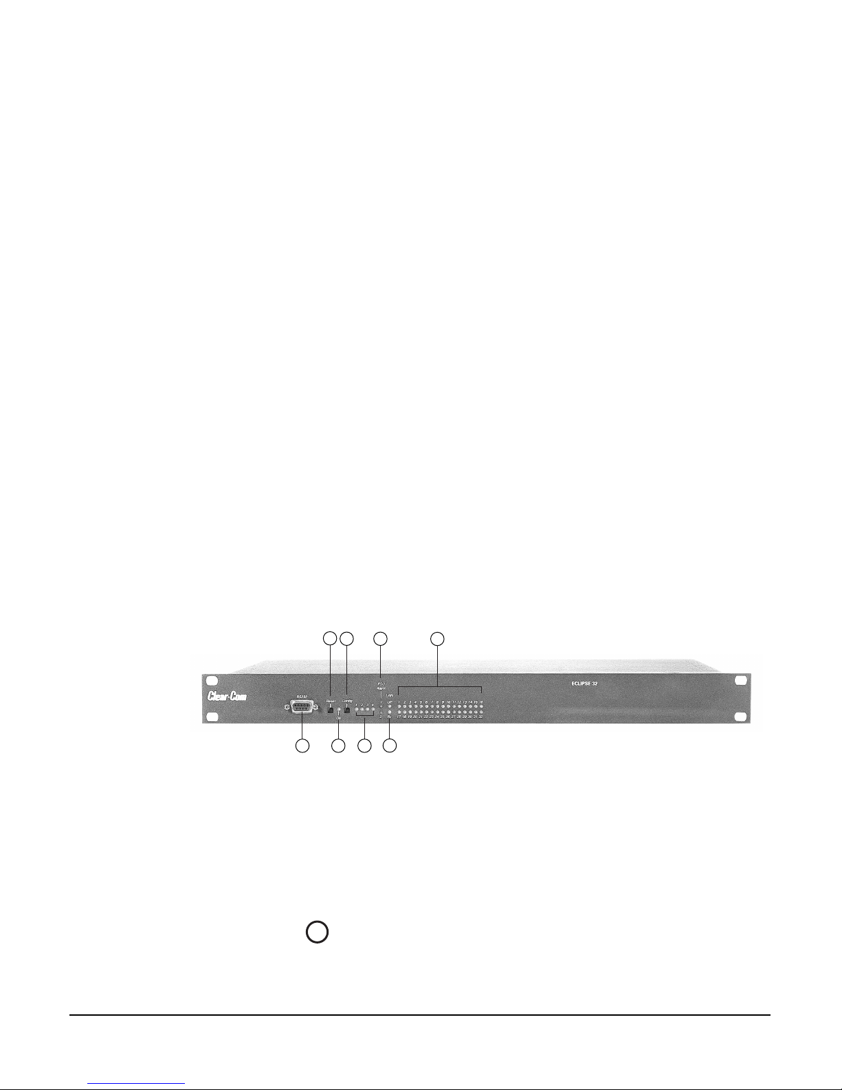
FRONT-PANEL CONTROLS AND LIGHTS
2
1
345
1 PC connector for computer
2 Reset button
3 OK light
4 Configuration ("config") button to
select among onboard configurations
1
PC CONNECTOR
The female 9-pin D-type socket labeled “PC” connects the matrix to an external
computer.
6
7
8
5 Configuration status lights to indicate currently active
configuration
6 Power supply alarm lights (1 and 2)
7 LAN status lights
8 Port status lights
Figure 1: Front Panel of Eclipse-32 Matrix
ECLIPSE-32 MATRIX INSTRUCTION MANUAL
2-1
Page 14

2
RESET BUTTON
Pressing the reset button causes the matrix to stop its current activity and to
restart. The same configuration that was active before you reset the system will be
active after you reset it.
During the reset, configuration information reloads to the matrix’s operational
memory from its non-volatile memory and the matrix starts running again from
the beginning.
3
OK LIGHT
When flashing, the “OK” light indicates that the Eclipse-32 matrix is running
successfully.
4
CONFIGURATION “CONFIG” BUTTON
The Eclipse-32 matrix can hold four complete system configurations in its
operational memory. You can activate one of the four configurations using the
CONFIG button on the matrix’s front panel.
When one of the four configurations is active, its front-panel light illuminates
steadily.
To select a new configuration:
1. Repeatedly tap the CONFIG button until the desired configuration’s light
(1,2,3, or 4) starts flashing.
2. While the desired configuration’s light flashes, press and hold the
configuration button for three seconds, until the light stops flashing, and
illuminates steadily.
The selected configuration then becomes the system’s active operational
configuration.
If you choose an invalid or blank configuration, all four configuration lights
steadily illuminate at the same time for about a second. The currently active
configuration will continue to operate and its front-panel light steadily
illuminates after the other lights go out.
5
CONFIGURATION STATUS LIGHTS
The four configuration status lights indicate which of the four onboard
configurations is currently active. The currently active configuration’s light
illuminates steadily.
6
POWER SUPPLY ALARM LIGHTS (1 AND 2)
2-2
An Eclipse-32 matrix has two internal power supply units. One power supply
unit can power an entire matrix; the second unit provides a backup in case of an
equipment failure.
ECLIPSE-32 MATRIX INSTRUCTION MANUAL
Page 15

In addition, the two supplies have separate IEC connectors to AC mains power,
and are designed for completely automatic and transparent changeover between
supplies in the event of an outage on one of the AC mains circuits.
The front-panel alarm lights do not illuminate under normal operating
conditions.
The following conditions cause a power-supply alarm light to illuminate:
• If any of the voltages produced by the first power supply unit fall below
normal levels.
• If any of the voltages produced by the second power supply unit fall below
normal levels.
Once the power-supply fault condition is no longer present, the power-supply
alarm light goes out.
7
LAN STATUS LIGHTS
When you connect a local area network to the matrix’s LAN port, the LAN UP
light steadily illuminates to indicate that the Eclipse-32 matrix is connected to a
local area network. The Rx light flashes when data is being received.
8
PORT STATUS LIGHTS
Each port status light corresponds to an RJ-45 connector on the matrix’s rear
panel to which an external device, such as an intercom station or interface, is
connected. An illuminated port light indicates that a device is connected to that
port, and that communications are running properly between the port and the
matrix.
ECLIPSE-32 MATRIX INSTRUCTION MANUAL
2-3
Page 16

CONNECTING THE MATRIX TO REMOTE DEVICES
The Eclipse-32 matrix connects to remote devices such as intercom stations,
interfaces, general purpose inputs and outputs, local area networks, and other
matrices through its rear-panel hardware connectors.
The following sections describe the rear-panel connectors. The Installation
Chapter of this manual gives pin assignments for each connector.
1
1 Two IEC AC power input connectors,
(1 per power-supply unit )
2 RJ-45 port connectors (36)
3 General purpose outputs connector
(male, 25-pin, D-type)
4 General purpose inputs connector
(female, 25-pin, D-type)
1
CONNECTING TO AC POWER
2
5 GPI/RLY interface connector (RJ-45)
6 Base loop connector (RJ-45)
7 LAN connector (RJ-45)
Figure 2: Rear Panel of an Eclipse-32 Matrix
3
4
5
6
An Eclipse-32 matrix’s rear panel contains two IEC AC power input sockets for
connecting AC mains power to the two power supplies. Each IEC socket
connects cable to one power supply, operating at an input voltage of 100 to 240
volts, between 50 and 60 hertz.
7
2-4
2
CONNECTING TO STATIONS AND INTERFACES
An Eclipse-32 matrix’s rear panel contains 36 RJ-45 sockets for connecting the
matrix to remote intercom stations and interfaces. These sockets are often called
“ports.” Each port socket is given a number on the rear-panel for easy
identification.
All ports contain a voice detection mechanism (“VOX”) that you program from
the Eclipse Configuration System software. VOX detection allows you to know
when the audio on a particular channel has exceeded a threshold. This is
particularly useful for channels that are inactive periodically, so that you are
visually cued in the software when audio appears on the line.
ECLIPSE-32 MATRIX INSTRUCTION MANUAL
Page 17

Note: General Purpose
Outputs are also referred to
as “relays.”
CONNECTING TO GENERAL-PURPOSE OUTPUTS
3
The male 25-pin D-type socket labeled “GP OUT” allows you to connect the
Eclipse-32 matrix to eight general purpose outputs (GPOs). General-purpose
outputs are single-pole double-throw relays with contact ratings of 30 VDC
(volts direct current) at 1 ampere.
A general purpose output or “relay” is a switch that you control remotely. You
program the relay in the Eclipse Configuration System software to close a contact
whenever an intercom station’s key is pressed. When the contact is closed, it
completes an electronic circuit’s signal path so that a remote device, such as a
light, is powered.
You can program a GPO to mute a speaker, to turn on an applause light, to turn
on a door lock, or to perform a variety of other functions. For example, to get the
attention of a station operator working in a high-noise environment such as a
control booth, you can program a relay to switch on a light at his station each
time he receives an incoming call, to ensure that he will not miss the call.
CONNECTING TO GENERAL-PURPOSE INPUTS
4
The female 25-pin D-type socket labeled “GP IN” allows you to connect the
Eclipse-32 matrix to eight general purpose inputs (GPIs).
You can connect an external logic device–such as an external foot switch, a
panel-mounted switch, or the logic output of some other device–to the “GP IN”
connector. When the external logic device is activated, it sends a control signal
into the matrix to perform one of several preset functions, such as turning an
intercom station’s microphone on or off, muting a microphone’s output, or
turning a station’s speaker off. You choose the function to perform, and the
station upon which it is performed, from the Eclipse Configuration System
programming software.
5
CONNECTING TO A GPI/RLY INTERFACE
The RJ-45 socket labeled “GPI/RLY Interface” connects the Eclipse-32 matrix to
a GPI-6 or RLY-6 card. The GPI-6 provides six general-purpose opto-isolated
logic inputs. The RLY-6 card provides six single-pole, double-throw relay
outputs.
Both card types mount in either an IMF-3 interface frame or an IMF-102
interface frame. You can operate up to ten GPI-6 or RLY-6 cards at one time
from the matrix by daisy-chaining the cards together. Each card has an IN and an
OUT connector for this purpose.
The RLY-6 and GPI-6 cards connect to the GPI/RLY interface connector using
shielded category-5 cable. For more information about the GPI-6 and RLY-6
cards, consult their respective manuals.
ECLIPSE-32 MATRIX INSTRUCTION MANUAL
2-5
Page 18

CONNECTING TO A SECOND ECLIPSE MATRIX
6
You connect shielded category-5 (CAT-5) cable from the “base loop” socket of
one Eclipse-32 matrix to the “base loop” socket of a second Eclipse-32 matrix to
form one non-blocking 64-port Eclipse matrix system. The cable connecting the
two matrices can be up to 1 meter (3.28 feet) long.
CONNECTING TO A LOCAL AREA NETWORK
7
The RJ-45 socket labeled “LAN” connects a local area network (LAN) to the
Eclipse-32 matrix through a standard Ethernet connection.
2-6
ECLIPSE-32 MATRIX INSTRUCTION MANUAL
Page 19

3
INSTALLING AN ECLIPSE-32
MATRIX
VERIFYING THE SHIPMENT
When you receive your Eclipse-32 system, inspect the boxes for shipping
damage. Report any shipping damage to the carrier. Your Eclipse-32 distributor
is not responsible for shipping damage.
Check the packing list and verify that you received every item on the list. Save all
packing materials in the event you need to return any items.
UNPACKING THE SYSTEM
You will receive an Eclipse-32 matrix, which contains the hardware and software
for the system. You need to supply:
• A standard 19 inch wide (48.26 cm) Electronics Industry Association rack in
which to install the matrix.
• A personal computer to run the Eclipse Configuration System programming
software (ECS). The Eclipse Configuration System software runs on Windows
XP, Windows Server 2003, Windows 2000, Windows ME, Windows 98, and
Windows NT (with service pack 6). When running ECS on Windows 98 or
Windows ME, however, both the client and server must run on the same
computer. When running ECS on other Windows operating systems, the
client and server can run on separate machines connected over a network.
• Shielded category-5 cables to connect to stations and interfaces.
INSTALLING THE ECLIPSE-32 MATRIX
The following overview gives you a summary of the steps required to install an
Eclipse-32 matrix. More detailed information on each step is provided in the
sections that follow.
To install an Eclipse-32 matrix:
1. Remove the Eclipse-32 matrix from its shipping carton.
2. Place the matrix in a standard Electronic Industry Association equipment rack.
3. Leave at least 2 inches (51 mm) of clearance on all sides of the matrix to ensure
proper airflow. Do not block ventilation vents.
4. Connect the power supplies to AC mains power using the IEC connectors on
the matrix’s rear panel. The matrix has two separate AC power entry
connectors for the two separate power supplies in the system.
ECLIPSE-32 MATRIX INSTRUCTION MANUAL
A fully equipped Eclipse-32 matrix requires 100 to 240 VAC at 50 to 60 Hz with
a maximum dissipation of 400 watts.
3-1
Page 20

WIRING THE MATRIX TO REMOTE DEVICES
The matrix holds the circuitry for connecting to, and communicating with, the
following:
• Thirty-two intercom stations or interfaces
• Eight general purpose outputs (GPOs or relays)
• Eight general purpose inputs (GPIs)
• Up to ten external GPI/RLY interfaces
• An additional Eclipse-32 matrix to form a 64-port linked system
• A local area network (LAN) connection for Ethernet-based communication
with a network
•An external computer
The following sections describe the wiring for these connections.
NOTE: The instruction manual Installing an Eclipse Matrix System: An Overview
gives complete details about wiring remote devices to the matrix. The Overview
manual also discusses RJ-45 cables and other types of cable required for system
installation.
1
1 Two IEC AC power input connectors,
(1 per power-supply unit )
2 RJ-45 port connectors (36)
3 General purpose outputs connector
(male, 25-pin, D-type)
4 General purpose inputs connector
(female, 25-pin, D-type)
1
WIRING TO AC MAINS POWER
The Eclipse-32 matrix has two IEC mains AC power connectors that provide
separate power inputs for the redundant power supplies. If you connect each AC
input to a different mains AC branch, one power supply will continue to operate
if the other supply’s main AC branch fails.
2
5 GPI/RLY interface connector (RJ-45)
6 Base loop connector (RJ-45)
7 LAN connector (RJ-45)
Figure 1: Wiring Interfaces to Rear-Panel Connectors
3
4
5
7
6
3-2
ECLIPSE-32 MATRIX INSTRUCTION MANUAL
Page 21

2
WIRING TO STATIONS AND INTERFACES
Eclipse uses a 4-pair (analog) or single-pair (digital) wiring scheme between the
matrix and stations. All Eclipse stations have built-in RJ-45 connectors.
4-Pair Analog
Four-pair analog wiring is done with shielded CAT5 RJ-45 cable.
• Pair 1 transmits analog audio from the matrix to the station.
• Pair 2 transmits digital data from the station back to the matrix.
• Pair 3 transmits audio from the station to the matrix.
• Pair 4 transmits digital data from the matrix back to the station.
RJ-45 CONNECTOR
AT MATRIX PORT
3
8765
2
1
4
Shielded category-5 cables wired pin-to-pin
Matrix Frame RJ-45 Pin Numbers
RS-422 Input +
(into Matrix)
RS-422 Input
(into Matrix)
Audio Input +
(into Matrix)
Audio Output +
(from Matrix)
Audio Output
(from Matrix)
Audio Input
(into Matrix)
RS-422 Output +
(from Matrix)
RS-422 Output
(from Matrix)
1
2
3
4
5
6
7
8
Views from
front of
connectors
Pair 2
Pair 1
Pair 3
Pair 4
RJ-45 CONNECTOR ON
STATION OR INTERFACE
4
7
8
6
1
2
3
5
Station RJ-45 Pin Numbers
RS-422 Output +
1
(from station)
RS-422 Output
2
(from station)
Audio Output +
3
(from station)
Audio Input +
4
(into station)
Audio Input
5
(into station)
Audio Output
6
(from station)
RS-422 Input +
7
(into station)
RS-422 Input
8
(into station)
ECLIPSE-32 MATRIX INSTRUCTION MANUAL
Pair 1 Audio output from Matrix to station
Pair 2 RS-422 data input from station to Matrix
Pair 3 Audio input from station to Matrix
Pair 4 RS-422 data output from Matrix to station
Figure 2: Wiring Matrix to Analog Station Using RJ-45
3-3
Page 22

Single-Pair Digital
Single-pair digital wiring is accomplished with double-shielded 24 AWG
conductor CAT-6E enhanced STP cable. Pair 1 transmits and receives
multiplexed digital and analog between the matrix frame and the station.
Note: Ensure that the “select” switch on the station’s rear panel is in the correct
position for the intended use.
ATT-T568B (Modular Jumpers Wired One to One)
Matrix Frame End
Station End
No Connection (NC)
No Connection (NC)
No Connection (NC)
Multiplexed Data/Audio
Multiplexed Data/Audio
No Connection (NC)
No Connection (NC)
No Connection (NC)
1
2
3
4
5
6
7
8
Pair 2
Pair 1
Pair 3
Pair 4
1
2
3
4
5
6
7
8
Figure 3: Wiring Matrix to Digital Station Using RJ-45
3-4
ECLIPSE-32 MATRIX INSTRUCTION MANUAL
Page 23

The DB-25 connector labeled “GP OUT” allows you to connect to the
Eclipse-32 matrix’s eight double-pole double-throw (DPDT) relays with contact
ratings of 30 VDC at 1A.
Each general-purpose output has a relay inside the Eclipse-32 matrix. When a
general-purpose output is inactive, the associated “common” pin on the GP
OUT connector will be shorted to the relevant “normally closed” pin. When a
general-purpose output becomes active, the short between the “common” pin
and the “normally closed” pin is broken and a new connection is made between
the “common” pin and the “normally open” pin.
DB-25 Male Connector
3
WIRING GENERAL-PURPOSE OUTPUTS
PIN
1
2
3
4
5
6
7
8
9
10
11
12
13
14
15
16
17
18
19
20
21
22
23
24
25
DESCRIPTION
RELAY 1 Common
RELAY 1 Normally Closed
RELAY 1 Normally Open
RELAY 2 Common
RELAY 2 Normally Closed
RELAY 2 Normally Open
RELAY 3 Common
RELAY 3 Normally Closed
RELAY 3 Normally Open
RELAY 4 Common
RELAY 4 Normally Closed
RELAY 4 Normally Open
GROUND
RELAY 5 Common
RELAY 5 Normally Closed
RELAY 5 Normally Open
RELAY 6 Common
RELAY 6 Normally Closed
RELAY 6 Normally Open
RELAY 7 Common
RELAY 7 Normally Open
RELAY 7 Normally Closed
RELAY 8 Common
RELAY 8 Normally Closed
RELAY 8 Normally Open
Common
RELAY 1
RELAY 2
RELAY 3
RELAY 4
30 VDC at 1 Ampere
Normally Closed
Normally Open
Common
Normally Closed
Normally Open
Common
Normally Closed
Normally Open
Common
Normally Closed
Normally Open
Digital Ground
1
14
2
15
3
16
4
17
5
18
6
19
7
20
8
21
9
22
10
23
11
24
12
25
13
Common
Normally Closed
Normally Open
Common
Normally Closed
Normally Open
Common
Normally Closed
Normally Open
Common
Normally Closed
Normally Open
RELAY 5
RELAY 6
RELAY 7
RELAY 8
ECLIPSE-32 MATRIX INSTRUCTION MANUAL
Figure 4: Pin Configuration of the General-Purpose Outputs Connector
3-5
Page 24

4
WIRING GENERAL-PURPOSE INPUTS
The DB-25 connector labeled “GP IN” connects the matrix to eight local
general-purpose inputs (GPIs).
When delivered from the factory, the general purpose inputs operate in
non-isolated mode. The non-isolated mode does not require that the externally
connected equipment powers the general-purpose input. The current is supplied
by a voltage output on the “GP IN” connector.
Non-Isolated Mode
Figure 5 shows the non-isolated connection.
EXTERNAL INPUT 1
EXTERNAL INPUT 2
+3V3
R29 1.5K
R30 1.5K
U
1
2
3
4
MOCD207-M
Figure 5: Non-Isolated Connection to Eclipse-32 GPI Connector
+3V3
+3V3
R
R
33K2
33K2
8
7
6
5
INPUT 1
INPUT 2
To cause an input to detect an active signal, you must send current from the
relevant input pin.
The external device should draw no current to cause an inactive input and at least
5 mA to cause an active input. The opto-isolator drive line contains a 1.5 kOhm
resistor to limit the current through the opto-isolator. You can therefore connect
the input pins directly to a ground pin to cause an active input.
The voltage level at the external input pin should not be allowed to go below
ground or above +6 V with respect to ground.
Opto-Isolated Mode
If required, you can operate the Eclipse-32 matrix in fully opto-isolated mode.
The unit must be taken out of service and powered down before you make this
change.
To operate the Eclipse-32 matrix in opto-isolated mode:
1. If the Eclipse-32 unit is connected to AC power, disconnect it from AC power.
2. Remove the top cover of the Eclipse-32 matrix by unscrewing the 12 M3 x 6
flat screws and lifting the cover upwards.
3. On the internal circuit board, move the jumper located under the heading
“J6” from pins 2-3 (marked “INT”) to pins 1-2 (marked “ISO”).
War nin g: A circuit board’s components include CMOS chips that are sensitive to
static electricity. Before touching the matrix’s circuit board with your hands, touch a
grounded metal object, such as any unpainted surface on the matrix, to dissipate static
3-6
ECLIPSE-32 MATRIX INSTRUCTION MANUAL
Page 25

EXTVIN+
7-24V
EXTERNAL INPUT 1
EXTERNAL INPUT 2
electricity.When handling a circuit board, be careful not to bend any of the board’s
connector pins or component leads.
Figure 6 shows the opto-isolated connection.
U
VIN8VOUT
C
+
10uF_25V
D
BYG22D
LM78L05ACM
1
C
+
10uF_10V
R29 1.5K
R30 1.5K
U
1
2
3
4
MOCD207-M
Figure 6: Opto-Isolated Connection to Eclipse-32 GPI Connector
+3V3
+3V3
R
R
33K2
33K2
8
7
6
5
INPUT 1EXTVIN-
INPUT 2
In this mode, a DC voltage of between 7 and 24 volts is required at the
EXTVIN+ pin with relation to the EXTVIN– pin. To cause an input to detect
an active signal, you must send current from the relevant input pin.
The external device should draw no current to cause an inactive input and at least
5 mA to cause an active input. The opto-isolator drive line contains a 1.5 kOhm
resistor to limit the current through the opto-isolator. You can therefore connect
the input pins directly to the EXTVIN– level to cause an active input.
The voltage level at the external input pin should not be allowed to go below
EXTVIN– or above +6 V with respect to EXTVIN–.
ECLIPSE-32 MATRIX INSTRUCTION MANUAL
3-7
Page 26

Pin Assignments for General-Purpose Inputs Connector
DB-25 Female Connector
PIN
1
2
3
4
5
6
7
8
9
10
11
12
13
14
15
16
17
18
19
20
21
22
23
24
25
DESCRIPTION
Logic Input 1
Logic Input 3
Logic Input 5
Logic Input 7
N/A
N/A
N/A
N/A
Ground
Ground
Ground
Ground
Ground
Logic Input 2
Logic Input 4
Logic Input 6
Logic Input 8
N/A
N/A
N/A
N/A
Voltage In+
Voltage In+
Voltage In–
Voltage In–
Logic Input 1
Logic Input 2
Logic Input 3
Logic Input 4
Ground
Ground
Ground
Ground
Ground
1
14
2
15
3
16
4
17
5
18
6
19
7
20
8
21
9
22
10
23
11
24
12
25
13
Logic Input 5
Logic Input 6
Logic Input 7
Logic Input 8
V IN+
V IN+
V IN–
V IN–
3-8
Figure 7: Pin Assignments for Eclipse-32 General-Purpose Inputs Connector
ECLIPSE-32 MATRIX INSTRUCTION MANUAL
Page 27

5
WIRING TO A GPI/RLY INTERFACE
The RJ-45 connector labeled “GPI/RLY” connects up to 10 RLY-6 or GPI-6
interfaces to the matrix.
The following sections give an overview of the wiring of these interfaces. For
more detailed discussion of wiring of interfaces in general, see the manual
Installing an Eclipse Matrix System: An Overview.
RLY-6 Interface Wiring
The RLY-6 relay interface module connects up to six programmable relays to the
matrix so that each relay is directly controlled from the matrix. Multiple RLY-6
interfaces can be daisy chained to provide connection of up to 60 relays to the
matrix. RLY-6 and GPI-6 modules can be mixed together up to the total limit of
60 items. Five RLY-6 and five GPI-6 modules would provide 30 relays and 30
inputs for a total of 60 inputs and outputs.
IMF-3 Interface Module Frame Wiring
To Ma t r i x
To connect the RLY-6 interface to the matrix, plug one end of an RJ-45 cable
(eight wires with no reversal) into the GPI/RLY INTERFACE connector on the
back of the matrix. Plug the other end into the top RJ-45 (CH. A MATRIX)
connector for the RLY-6.
To connect an additional RLY-6 interface, plug one end of a short RJ-45 cable
into the lower RJ-45 (CH. B MATRIX) for the first RLY-6. Then, plug the other
end into the top RJ-45 (CH. A MATRIX) connector for the additional RLY-6.
Additional RLY-6 interfaces are added in the same way, using daisy-chain wiring.
If there are multiple RLY-6 interfaces, the relays in the first will be numbered 1
through 6, the second will be numbered 7 through 12, etc. GPI-6 interfaces can
be mixed in this daisy-chained scheme. The maximum combined length of all
the RJ-45 cables should not exceed 20 ft. (6 m). Refer to Figure 8.
GPI/RLY
Interface
#2
Connector
R LY- 6
#1
Por ts
RJ-45 RJ-45 RJ-45 RJ-45 RJ-45
DB-9 DB-9 DB-9 DB-9 DB-9
RJ-45 RJ-45 RJ-45 RJ-45 RJ-45
DB-9 DB-9 DB-9 DB-9 DB-9
Other
Interfaces
Rear View of IMF-3 Frame
GPI-6
#2
GPI-6
#1
R LY- 6
ECLIPSE-32 MATRIX INSTRUCTION MANUAL
Figure 8: Rear View of IMF-3 Frame
3-9
Page 28

To External Device
To connect external devices to the RLY-6 interface, use the two DB-9M
connectors on the rear cable assembly panel for the interface. Figure 9 shows the
pin assignment of these connectors as viewed from the matrix side of the
connector.
If a DB-9F is plugged into the connector labeled CH. A I/O, relays 1 to 3 are
available on that connector. The connector labeled CH. B I/O has the contacts
for relays 4 to 6. In Figure 9, the labels on the pins apply to either connector.
Example: #1/4 COM refers to the wiper of relay 1 if it is connected to CH. A
and the wiper of relay 4 if it is connected to CH. B.
1
6
2
7
3
8
4
9
5
#1/4 Normally Closed
#1/4 COM
#1/4 Normally Open
#2/5 Normally Closed
#2/5 COM
#2/5 Normally Open
#3/6 Normally Closed
#3/6 COM
#3/6 Normally Open
Figure 9: RLY-6 Interface DB-9M Connector Pinout
IMF-102 Interface Module Frame Wiring
The wiring of a RLY-6 interface that is placed in an IMF-102 interface frame is
the same as the wiring for a RLY-6 interface placed in an IMF-3 interface frame.
The only difference is that an IMF-102 interface frame houses only two
interfaces, and they are mounted horizontally rather than vertically in the frame.
Refer to the respective manuals for these interfaces and frames in the Eclipse
manual set for more information.
3-10
Configuration
To associate a relay to a label, use the Eclipse Configuration System, as described
in its manual.
GPI-6 Interface Wiring
The GPI-6 input interface module connects up to six programmable inputs to
the matrix so that each input can control a predefined matrix function. Multiple
GPI-6 interfaces can be daisy-chained to provide connection of up to 60 inputs
to the matrix. RLY-6 and GPI-6 interfaces can be mixed together up to the total
ECLIPSE-32 MATRIX INSTRUCTION MANUAL
Page 29

limit of 60 items. Five RLY-6 and five GPI-6 interfaces would provide 30 relays
and 30 inputs for a total of 60 inputs and outputs.
IMF-3 Interface Module Frame Wiring
To Ma t r i x
To connect the GPI-6 to the matrix, plug one end of an RJ-45 cable (eight wires
with no reversal) into the GPI/RLY INTERFACE connector on the back of the
matrix. Plug the other end into the top RJ-45 (CH. A MATRIX) connector for
the GPI-6.
To connect an additional GPI-6 interface, plug one end of a short RJ-45 cable
into the lower RJ-45 (CH. B MATRIX) for the first GPI-6. Then, plug the other
end into the top RJ-45 (CH. A MATRIX) connector for the additional GPI-6.
Additional GPI-6 interfaces are added in the same way, using daisy-chain wiring.
If you require multiple GPI-6 interfaces, the inputs in the first will be numbered
1 through 6, the inputs in the second will be numbered 7 through 12, etc. RLY-6
interfaces can be mixed in this daisy-chained scheme. The maximum combined
length of all the RJ-45 cables should not exceed 20 ft. (6 m).
To External Device
To connect external devices to the GPI-6 interface, use the two DB-9M
connectors on the rear cable assembly panel for the interface. Figure 10 shows the
pin assignment of these connectors as viewed from the matrix side of the
connector.
If a DB-9F is plugged into the connector labeled CH. A I/O, inputs 1 through 3
are available on that connector. The connector labeled CH. B I/O has inputs 4
through 6. In Figure 10, the labels on the pins apply to either connector.
1
6
2
7
3
8
4
9
5
Figure 10: GPI-6 Interface DB-9M Connector Pinout
#1/4 Input A
#1/4 Input B
#2/5 Input A
#2/5 Input B
#3/6 Input A
#3/6 Input B
Ground
Power Source
Ground
ECLIPSE-32 MATRIX INSTRUCTION MANUAL
3-11
Page 30

GPI-6 I/O DB-9M
GPI-6 I/O DB-9M
1
6
2
7
3
8
X
4
9
5
1
6
2
7
3
8
4
9
5
X
X
X
Figure 11: GPI-6 Application Examples
Figures 10 and Figure 11 show how to connect switches or contacts using the
power source provided by the GPI-6 module or powering switches from external
sources. Each input can be wired to be isolated from each other as a further
variation.
IMF-102 Interface Module Frame Wiring
The wiring of a GPI-6 interface that is placed in an IMF-102 interface frame is
the same as the wiring for a GPI-6 interface placed in an IMF-3 interface frame.
The only difference is that an IMF-102 interface frame houses only two
interfaces, and they are mounted horizontally rather than vertically in the frame.
Refer to the respective manuals for these interfaces and frames in the Eclipse
manual set for more information.
Configuration
To define an input function, use the Eclipse Configuration System program, as
described in its manual.
3-12
ECLIPSE-32 MATRIX INSTRUCTION MANUAL
Page 31

WIRING TO A SECOND ECLIPSE MATRIX
6
The RJ-45 connector labeled “Base Loop” connects the Eclipse-32 matrix to a
second Eclipse-32 matrix’s “Base Loop” connector to form one non-blocking 64
port Eclipse system.
To make this connection, use a specially constructed screened CAT-5 cable of
maximum length 1 meter (3.28 feet). The cable is wired as shown in Table 1.
CABLE END 1 WIRE COLOR CABLE END 2
Pin 1 white/orange Pin 3
Pin 2 orange Pin 6
Pin 3 white/green Pin 1
Pin 4 blue Pin 4
Pin 5 white/blue Pin 5
Pin 6 green Pin 2
Pin 7 white/brown Pin 7
Pin 8 brown Pin 8
Table 1: Pin Configuration of Base Loop Connector
WIRING TO A LOCAL AREA NETWORK
7
The LAN connector has standard Ethernet pin assignments.
LAN1 and LAN2
Ethernet RJ-45 Connectors
4
PIN
7
8
6
1
2
3
4
5
6
7
8
Transmit data +
Transmit data –
Receive data +
Unused
Unused
Receive data –
Unused
Unused
5
FUNCTION
1
2
3
ECLIPSE-32 MATRIX INSTRUCTION MANUAL
Figure 12: Pin Assignments for LAN Connector
3-13
Page 32

WIRING TO A COMPUTER
The DB-9 connector labeled “PC” connects the Eclipse-32 matrix to an external
computer. This connector is located on the Eclipse-32 matrix’s front panel.
To connect a computer to the matrix, run cable from the matrix’s “PC”
connector to the PC’s serial port. The maximum recommended length of the
cable is approximately 10 feet (3 meters).
A computer has either a 9-pin serial port or a 25-pin serial port. Figure 13 shows
the wiring for a 9-pin port. Figure 14 shows the wiring for a 25-pin port.
Matrix Frame
Computer Serial Port DB-9F
Cable Connector
"IBM-PC RS-232"
DB-9M Cable Connector
NOTE: If your computer
does not have a serial port,
and only offers USB,
adapters are generally
available from computer
parts suppliers.
1
6
Receive (RXD)
2
7
3
Transmit (TXD)
Transmit (TXD)
Receive (RXD)
8
4
9
5
Ground (GND)
1
6
2
7
3
8
4
9
5
Figure 13: Wiring the Matrix DB-9M to a DB-9F Computer Serial Port Connector
1
Computer Serial Port
DB-25F Cable
Connector
14
15
16
17
18
19
20
21
22
23
24
25
Transmit (TXD)
2
Receive (RXD)
3
4
5
6
7
8
9
10
11
12
13
Transmit (TXD)
Receive (RXD)
Ground (GND)
1
2
3
4
5
6
7
8
9
Eclipse Frame
"IBM-PC RS-232"
DB-9M Cable
Connector
3-14
Figure 14: Wiring the Matrix DB-9M to a DB-25F Computer Serial Port Connector
ECLIPSE-32 MATRIX INSTRUCTION MANUAL
Page 33

4
You can reach Clear-Com’s
customer service
department 24 hours a day,
7 days a week, at
(510)496-6666. You can
email the department at the
support addresses listed on
our Web site at
www.clearcom.com.
MAINTAINING AN ECLIPSE-32
MATRIX
Clear-Com’s customer service department will consult on the telephone about
repair problems. You can also send equipment to the department for repair. You
can reach the customer service department 24 hours a day, 7 days a week, at
(510) 496-6666. You can email the department at the support email addresses
listed on our Web site at www.clearcom.com.
RECOMMENDED SPARE PARTS
To facilitate quick repair of the system with minimum downtime, Clear-Com
recommends keeping the following spare system components in good working
condition at all times:
• One of each type of intercom station in the system
• One of each type of interface in the system
Due to the complexity of the system, field service generally should be limited to
isolating the specific component of the system with the problem.
DUAL, INDEPENDENT POWER SUPPLIES
The Eclipse-32 matrix includes two internal power supply units. One power
supply unit can power an entire matrix; the second unit provides a backup in case
of an equipment failure.
In addition, the two supplies have separate IEC connectors to AC mains power,
and are designed for completely automatic and transparent changeover between
supplies in the event of a power failure on one of the AC branches.
TECHNICAL SUPPORT
To ensure complete and timely support to its customers, VGC maintains
Technical Service Centers (TSC) staffed by qualified technical personnel. A
Technical Service Center is staffed to respond to all technical inquiries and to
troubleshoot technical problems regarding all products supplied by VGC. A TSC
is fully available to VGC’s customers during the full course of their warranty period.
Instructions for reaching our Technical Service Centers are given below.
For technical support from Europe, the Middle East, and Africa
Call: +49 40 66 88 40 40 Monday through Friday 09:00 – 17:00 (GMT)
+49 40 66 88 40 41 24hrs, any day (But you must have your PIN number
ready.)
ECLIPSE-32 MATRIX INSTRUCTION MANUAL
4-1
Page 34

Web site: www.drake-uk.com (Click the 24 X 7 User Support symbol on the
Web site)
Email: drake@avc.de
For technical support from the Americas and Asia
Call: +1 510 496 6666
Web sit e: www.clearcom.com
Email: support@clearcom.com
FAX: +1 510 496 6610
24hrs, any day
4-2
ECLIPSE-32 MATRIX INSTRUCTION MANUAL
Page 35

5
SPECIFICATIONS
0 dBu is referenced to 0.775 volts RMS
General
Height 44 mm or 1.75 inches (1 RU)
Width 482 mm (19 inches)
Depth 300 mm (12 inches)
Weight 5 kg max.
Power Consumption 500 W Max. per inlet
Number of Station Compatible Ports 32
Number of Analog Audio Ports 4
Number of Expansion Modules 1
Number of Power Supply Units 2
Maximum Number of Ports Per System 72 with 2 Eclipse-32 units; 64 station ports
Matrix Performance
Sample Rate 48 kHz
Resolution 24 bit
Frequency Response @ 48 kHz sampling 30 Hz – 22 kHz ± 3 dBu
Crosstalk (adjacent channel) <–70 dBu
Nominal Level 0 dBu
Matrix headroom 18 dBu
Distortion <0.05 %, @ 0 dBu, 300 Hz to 10 kHz;
<0.1 %, @ 0 dBu, 100 Hz to 20 kHz
Off Noise <–98 dBu relative to +18 dBu,
20 Hz - 22kHz
On Noise <–83 dB relative to +18 dBu, 20 Hz - 22 kHz
Key Response, Intra-System <40 ms for audio route
Linked Systems <60 ms for audio between matrices
Temperature 0 to +40 C, ambient;
-55 to +70 C, storage
Humidity, Maximum 90% non-condensing
°
°°
ECLIPSE-32 MATRIX INSTRUCTION MANUAL
Matrix Interfaces
GPI inputs 8 total; opto-isolated
GPI outputs (relays) 8 total; isolated relay contacts
GPI connector 25-pin D-type socket on rear panel
GPO connector 25-pin D-type plug on rear panel
External GPI-6/RLY-6 RJ-45 on rear panel
5-1
Page 36

Network 10/100 Base-T Ethernet
maximum distance: 100 meters
connector RJ-45
Serial PC RS-232
Baud rate: 57600
Maximum distance: 10 meters
Number of ports: 1
Connector: 9-way D-type socket on front
System Programming
Crosspoint Level Control 0.355 dB steps
Input Level Control 0.355 dB steps
Output Level Control 0.355 dB steps
VOX Input Detection Threshold 0 dB to – 40 dB adjustable
Minimum PC Requirements
Processor Pentium II 400 MHz
Memory 128 MB RAM
Hard Disk 150 MB
Input Devices CD-ROM Drive
Display Resolution GAD
User Entry Keyboard, Mouse
Ports 2 serial ports and/or network IEEE 802.3
Ethernet card
Network IEEE 802.3 Ethernet Card
Operating Sy stems Wi ndows 98 SE/ 2000 / XP / 20 03
Note: When running Windows 98, the client and server must run on the same computer.
5-2
Recommended PC Requirements
Processor Pentium 800 MHz or greater
Memory 256 MB or greater
Free Space 500 MB
Display Resolution 1600 X 1200
Operating System XP SP2
Power Supply Unit
Quantity 2 per matrix
Mounting Internal
AC Power Input IEC (1 per PSU)
Input Voltage AC 100 V to 240 V, 50/60 Hz
Power Consumption 400 W maximum
Alarm Indicators LEDs viewable from front of rack
ECLIPSE-32 MATRIX INSTRUCTION MANUAL
Page 37

Supported Stations and Interfaces: ICS-1008, ICS-1016, ICS-52, ICS-92,
ICS-62, ICS-102, IMF-102, ICS-2003, i-Station family, XPL-22, XPL-12,
IMF-3, TEL-14, CCI-22, FOR-22, RLY-6, GPI-6, DIG-2, 4000 Series Stations.
Notice About Specifications
While Clear-Com makes every attempt to maintain the accuracy of the
information contained in its product manuals, that information is subject to
change without notice. Performance specifications included in this manual are
design-center specifications and are included for customer guidance and to
facilitate system installation. Actual operating performance may vary.
ECLIPSE-32 MATRIX INSTRUCTION MANUAL
5-3
Page 38

5-4
ECLIPSE-32 MATRIX INSTRUCTION MANUAL
Page 39

6
GLOSSARY
Bus A bus is the channel or path between the components in the matrix along
which electrical signals flow to carry information from one component to the
next. In the Eclipse matrix the bus is located in the etched surface of the
midplane.
Call Signal A call signal is an electronic signal sent from one station or
interface to another. A call signal can be audible and/or visual. Typically a call
signal is sent to get the attention of a station operator who may have turned
down their intercom speaker’s volume or removed their headset. It can also be
sent to activate an electronic relay.
Category-5 cable EIA/TIA 568 category specification relating to network
cabling. Shielded category-5 cabling is required for Eclipse matrix wiring.
Central Matrix The term “central matrix” is used to differentiate the central
hardware of the intercom system from the connected remote devices. The central
matrix consists of: (1) the metal housing for the circuit cards and power supplies,
(2) the circuit board, (3) the power supplies, (3) the rear panel connectors which
connect the matrix’s hardware to remote stations and interfaces.
Destination A device—such as an intercom station, beltpack, or interface—to
which you send audio signals. The device from which you send audio signals is
called a “source.”
Duplex All real-time communication between individuals talking face to face is
full duplex, meaning that you can both talk and listen simultaneously. The
Eclipse-32 matrix provides full-duplex audio.
Eclipse Configuration System Web-based software program that guides
the operation of the central matrix circuit cards and connected remote stations.
Ethernet International standard which describes how information is
transmitted across a network. Provides for the efficient organization of network
components.
IFB “Interruptible Foldback.” The term “foldback” refers to sending “program”
audio, or some other audio mix, back to the announcer while he is on the air.
Doing so allows the announcer to monitor himself, other announcers, videotapes
of commercials, or some mix of sources, while he is on the air. This is typically
found in television news and live broadcast events.
The announcer typically wears a small ear piece so he can hear the selected
foldback audio mix. When a director wants to give directions to the announcer
on air, or to announce changes in the program, he must “interrupt” the foldback.
To do this, he uses a channel specifically set up to interrupt the foldback audio.
Interface A piece of electronic hardware designed to convert the 4-wire signals
of a central matrix port to some other form of communication, such as 2-wire
ECLIPSE-32 MATRIX INSTRUCTION MANUAL
6-1
Page 40

party line, telephone, etc. The interface is connected to a central matrix port.
The external non-4-wire device is then connected to the interface.
ISO The ISO function, short for “station ISOlation,” allows you to call a
destination and interrupt all of that destination’s other audio paths and establish
a private conversation. When you complete your call, the destination’s audio
pathways are restored to their original state before the interruption.
Label A label is an alphanumeric name of up to five characters that identifies a
source, destination, or control function accessed by your intercom station. Labels
appear in the displays of the intercom station. Labels can identify stations, ports
interfaced to other external equipment, fixed groups, party lines, and special
control functions.
Non-volatile memory Data stored in the CPU’s firmware (ROM) that is not
lost when the power is turned off.
Port Any of the Eclipse matrix’s 36 input/output RJ-45 connectors that are used
to connect cable from the matrix to remote stations and interfaces. Each “port”
connects to a separate audio channel in the matrix intercom system.
Program Any separate audio source that is fed into the intercom channels. In
television applications, for example, “program” audio is the audio that is
broadcast on air.
Remote Station Any intelligent intercom device connected to the rear-panel
ports of the central matrix. This term does not refer to devices connected
through interfaces.
Rack Unit or RU Standardized unit of mounting space on a rack panel. Each
rack unit is 1.75 inches (44.45 mm) of vertical mounting space. Therefore 1 RU
is 1.75 inches (44.45 mm) of vertical mounting space, 2 RU is 3.5 inches (88.9
mm), 3 RU is 5.25 inches (133.35 mm), and so on.
Sidetone The sound of your own voice heard in your own earphone as you
speak.
Source In this manual, the term “source” refers to a device—such as an
intercom station, interface, or beltpack —that sends audio into the matrix. The
device to which audio is sent is called a “destination.”
VOX In the Eclipse-32 system, when audio at a station exceeds a threshold, the
Eclipse Configuration System software visually cues you. The threshold level is
set in the Eclipse Configuration System software.
6-2
ECLIPSE-32 MATRIX INSTRUCTION MANUAL
Page 41

7
VITEC GROUP COMMUNICATIONS
WARRANTY
Vitec Group Communications (VGC) guarantees this product to be free of
manufacturing defects in material and workmanship under normal use for a
period of two years from the date of purchase.
Clear-Com offers 24/7
customer support.
Return authorization
numbers are required for all
returns.
Both warranty and
non-warranty repairs are
available.
TECHNICAL SUPPORT
To ensure complete and timely support to its customers, VGC maintains
Technical Service Centers (TSC) staffed by qualified technical personnel. A
Technical Service Center is staffed to respond to all technical inquiries and to
troubleshoot technical problems regarding all products supplied by VGC. A TSC
is fully available to VGC’s customers during the full course of their warranty period.
Instructions for reaching our Technical Service Centers are given below.
For technical support from Europe, the Middle East, and Africa
Call: +49 40 66 88 40 40 Monday through Friday 09:00 – 17:00 (GMT)
+49 40 66 88 40 41 24hrs, any day (But you must have your PIN number
ready.)
Web site: www.drake-uk.com
Web site)
Email: drake@avc.de
For technical support from the Americas and Asia
Call: +1 510 496 6666
Web sit e: www.clearcom.com
24hrs, any day
(Click the 24 X 7 User Support symbol on the
VITEC GROUP COMMUNICATIONS WARRANTY
Email: support@clearcom.com
FAX: +1 510 496 6610
EXCEPTIONS
This warranty does not include damage to a product resulting from cause other
than part defect and malfunction. The VGC warranty does not cover any defect,
malfunction, or failure caused beyond the control of VGC, including
unreasonable or negligent operation, abuse, accident, failure to follow
instructions in the manual, defective or improperly associated equipment,
attempts at modification and repair not approved by VGC, and shipping
damage. Products with their serial numbers removed or defaced are not covered
by this warranty.
7-1
Page 42

WARRANTY REPAIRS
While VGC will ensure complete system integrity by providing whatever support
is necessary to resolve any failure covered under the terms of the warranty, the
normal procedure will be to repair or replace any defective Line Replaceable Unit
(LRU) that is returned to VGC during the warranty period.
A Line Replaceable Unit (LRU) is defined as: an assembly that can be safely
removed from the system and readily replaced by plugging in a new unit. In the
case of ancillary items such as power supplies, the entire power supply would be
returned. Whereas, in the case of circuit cards, control panels, etc., only these
assemblies would be returned for repair. All equipment provided by VGC is
covered under the warranty.
This warranty does not include defects arising from installation (when not
performed by VGC), lightning, power outages and fluctuations, air conditioning
failure, improper integration with non-approved components, defects or failures
of customer furnished components resulting in damage to VGC provided
product.
NON-WARRANTY REPAIRS
Equipment that is not under warranty must be sent prepaid to VGC. If
requested, an estimate of repair costs will be issued prior to service. Once repair is
approved and completed, the equipment will be shipped freight collect from the
TSC.
REPLACEMENT UNITS
Should VGC determine, in its reasonable discretion, that any part of a product is
defective due to faulty materials or workmanship, VGC shall at its expense,
repair or replace such part and return the repaired/replacement part to the
customer. The provisions of this warranty shall apply to the repaired/replacement
part for the unexpired portion, if any, of the warranty period.
EMERGENCY ON-SITE ASSISTANCE
VGC can provide emergency on-site technical assistance in support of warranty
activities. The level of support effort required will be decided on a case-by-case
basis. VGC has the qualified technical staff to support any and all emergency site
activities should they occur.
LIABILITY
The foregoing warranty is VGC’s sole and exclusive warranty. There are no other
warranties (including without limitation warranties for consumables and other
supplies), or guarantees, expressed or implied (including, without limitation, any
warranties of merchantability or fitness for a particular purpose), of any nature
whatsoever, whether arising in contract, tort, negligence of any degree, strict
liability or otherwise, with respect to the products or any part thereof delivered
VITEC GROUP COMMUNICATIONS WARRANTY
7-2
Page 43

hereunder and/or with respect to any non-conformance or defect in any such
product and/or part thereof delivered hereunder and/or with respect to any
non-conformance or defect in any such product and/or part thereof delivered
hereunder, or any other warranties or guarantees, including but not limited to
any liability of VGC for any consequential and/or incidental damages and/or
losses (including loss of use, revenue, and/or profits). In any event, the maximum
extent of VGC’s liability to customer hereunder shall not under any
circumstances exceed the cost of repairing or replacing any part(s) fount to be
defective within the warranty period as aforesaid.
RETURNING EQUIPMENT FOR REPAIR
All equipment returned for repair must be accompanied by:
• Documentation stating the return address, telephone number, date of
purchase, and a description of the problem.
• A repair reference number.
To obtain a repair reference number, contact the appropriate Technical Service
Center at the phone numbers or Web sites listed below. Our representatives will
give you instructions and addresses for returning your equipment. By talking
with our representatives, many problems can be resolved on the phone.
For returns from Europe, the Middle East, and Africa
Call: +49 40 66 88 40 40 Monday through Friday 09:00 – 17:00 (GMT)
+49 40 66 88 40 41 anytime, any day
(But you must have your PIN number ready)
Web sit e: www.drake-uk.com
Web site)
Email: drake@avc.de
For returns from the Americas and Asia
Call: +1 510 496 6666
Web sit e: www.clearcom.com
Email: support@clearcom.com
FAX: +1 510 496 6610
(Click the 24 X 7 User Support symbol on the
or send a
VITEC GROUP COMMUNICATIONS WARRANTY
7-3
Page 44

WARRANTY VALIDATION
To validate your warranty, fill in the information below, and mail it to your local
Technical Service Center.
VITEC GROUP COMMUNICATIONS WARRANTY
7-4
 Loading...