

Page 1

INSTALLING THE ECLIPSE MATRIX:
AN OVERVIEW
Page 2

Installing the Eclipse Matrix : An Overview
© 2007 Vitec Group Communications
www.clearcom.com
All Rights Reserved
Part Number 810298 Rev. 5
Vitec Group Communications, LLC.
850 Marina Village Parkway
Alameda, CA 94501
U.S.A.
Vitec Group Communications
7400 Beach Drive
Cambridge Research Park
Cambrideshire
United Kingdom
CB25 9TP
Vitec Group Communications
Room 1806, Hua Bin Building
No. 8 Yong An Dong Li
Jian Guo Men Wai Ave
Chao Yang District
Beijing, P.R. China 100022
Clear-Com is a registered trademark of Vitec Group Communications.
The Clear-Com logo is a registered trademark of Vitec Group Communications.
Eclipse is a registered trademark of Vitec Group Communications.
Page 3

INSTALLATION OVERVIEW
i
CONTENTS
INSTALLATION OVERVIEW 1-1
Introduction . . . . . . . . . . . . . . . . . . . . . . . . . . . . . . . . . . . . . . . . . . . . . . . . . 1-1
Step-by-Step Installation . . . . . . . . . . . . . . . . . . . . . . . . . . . . . . . . . . . . . . . . 1-2
Verify the Shipment . . . . . . . . . . . . . . . . . . . . . . . . . . . . . . . . . . . . . . . . 1-2
Select Locations for Your Components . . . . . . . . . . . . . . . . . . . . . . . . . . . 1-2
Determine Your Wiring Requirements. . . . . . . . . . . . . . . . . . . . . . . . . . . . 1-2
Install Components in Rack . . . . . . . . . . . . . . . . . . . . . . . . . . . . . . . . . . . 1-2
Install Cables . . . . . . . . . . . . . . . . . . . . . . . . . . . . . . . . . . . . . . . . . . . . . . . 1-3
Connect Cables and Auxiliary Wiring . . . . . . . . . . . . . . . . . . . . . . . . . . . . 1-3
Connect to Mains AC Power . . . . . . . . . . . . . . . . . . . . . . . . . . . . . . . . . . . 1-4
Matrices. . . . . . . . . . . . . . . . . . . . . . . . . . . . . . . . . . . . . . . . . . . . . . 1-4
Stations . . . . . . . . . . . . . . . . . . . . . . . . . . . . . . . . . . . . . . . . . . . . . . 1-4
4000 Series II Panels . . . . . . . . . . . . . . . . . . . . . . . . . . . . . . . . . . . . 1-4
V-Series Panels. . . . . . . . . . . . . . . . . . . . . . . . . . . . . . . . . . . . . . . . . 1-5
Configure the System . . . . . . . . . . . . . . . . . . . . . . . . . . . . . . . . . . . . . . . . 1-5
Verify the Operation of the System . . . . . . . . . . . . . . . . . . . . . . . . . . . . . . 1-5
Matrix Indicators to Verify . . . . . . . . . . . . . . . . . . . . . . . . . . . . . . . . . . 1-5
Eclipse Omega. . . . . . . . . . . . . . . . . . . . . . . . . . . . . . . . . . . . . . . . . 1-5
Eclipse Median . . . . . . . . . . . . . . . . . . . . . . . . . . . . . . . . . . . . . . . . 1-5
Eclipse Pico . . . . . . . . . . . . . . . . . . . . . . . . . . . . . . . . . . . . . . . . . . . 1-6
Eclipse-32 . . . . . . . . . . . . . . . . . . . . . . . . . . . . . . . . . . . . . . . . . . . . 1-6
PLACING SYSTEM COMPONENTS 2-1
Component Location Requirements . . . . . . . . . . . . . . . . . . . . . . . . . . . . . . . 2-1
Eclipse Matrices. . . . . . . . . . . . . . . . . . . . . . . . . . . . . . . . . . . . . . . . . . . . . 2-1
Eclipse Omega Matrix . . . . . . . . . . . . . . . . . . . . . . . . . . . . . . . . . . . . . . 2-1
Eclipse Median Matrix. . . . . . . . . . . . . . . . . . . . . . . . . . . . . . . . . . . . . . 2-2
Eclipse Pico Matrix . . . . . . . . . . . . . . . . . . . . . . . . . . . . . . . . . . . . . . . . 2-2
Eclipse-32 Matrix . . . . . . . . . . . . . . . . . . . . . . . . . . . . . . . . . . . . . . . . . 2-2
Interface Frame(s) and Power Supplies. . . . . . . . . . . . . . . . . . . . . . . . . . . . 2-3
IMF-3 Interface Module Frame. . . . . . . . . . . . . . . . . . . . . . . . . . . . . . . 2-3
IMF-102 Interface Module Frame. . . . . . . . . . . . . . . . . . . . . . . . . . . . . 2-4
DIF-102 Interface Module Frame . . . . . . . . . . . . . . . . . . . . . . . . . . . . . 2-4
Intercom Panels and Expansion Panels. . . . . . . . . . . . . . . . . . . . . . . . . . . . 2-4
External Computer . . . . . . . . . . . . . . . . . . . . . . . . . . . . . . . . . . . . . . . . . . 2-5
POWERING SYSTEM COMPONENTS 3-1
Page 4

INSTALLATION OVERVIEW
ii
Power Requirements . . . . . . . . . . . . . . . . . . . . . . . . . . . . . . . . . . . . . . . . . . . 3-1
Matrices. . . . . . . . . . . . . . . . . . . . . . . . . . . . . . . . . . . . . . . . . . . . . . . . . . . 3-1
Eclipse Omega Matrix . . . . . . . . . . . . . . . . . . . . . . . . . . . . . . . . . . . . . . 3-1
Eclipse Median Matrix. . . . . . . . . . . . . . . . . . . . . . . . . . . . . . . . . . . . . . 3-2
Eclipse Pico Matrix . . . . . . . . . . . . . . . . . . . . . . . . . . . . . . . . . . . . . . . . 3-2
Eclipse-32 Matrix . . . . . . . . . . . . . . . . . . . . . . . . . . . . . . . . . . . . . . . . . 3-2
Intercom Panels . . . . . . . . . . . . . . . . . . . . . . . . . . . . . . . . . . . . . . . . . . . . . 3-2
i-Series Intercom Panels. . . . . . . . . . . . . . . . . . . . . . . . . . . . . . . . . . . . . 3-2
ICS-2003 Intercom Panels. . . . . . . . . . . . . . . . . . . . . . . . . . . . . . . . . . . 3-2
ICS-52/62/92/102 Intercom Panels. . . . . . . . . . . . . . . . . . . . . . . . . . . . 3-3
XPL-12/22 Display Expansion Panels and AP-22 Assignment Panels . . 3-3
4000 Series II Panels and Expansion Panels . . . . . . . . . . . . . . . . . . . . . . 3-3
V-Series Panels and Expansion Panels . . . . . . . . . . . . . . . . . . . . . . . . . . 3-3
Interface Module Frame Power Supply Requirements . . . . . . . . . . . . . . . . 3-3
IMF-3 Interface Module Frame. . . . . . . . . . . . . . . . . . . . . . . . . . . . . . . 3-3
IMF-102 Interface Module Frame. . . . . . . . . . . . . . . . . . . . . . . . . . . . . 3-5
DIF-102 Interface Module Frame . . . . . . . . . . . . . . . . . . . . . . . . . . . . . 3-5
WIRING SYSTEM COMPONENTS 4-1
Summary of Wiring Systems . . . . . . . . . . . . . . . . . . . . . . . . . . . . . . . . . . . . . 4-1
RJ-45 Cables . . . . . . . . . . . . . . . . . . . . . . . . . . . . . . . . . . . . . . . . . . . . . . . 4-1
General Discussion About RJ-45 Connector Cables . . . . . . . . . . . . . . . 4-1
Clear-Com Kits and Recommendation . . . . . . . . . . . . . . . . . . . . . . . . . 4-2
Installing RJ-45 Connectors . . . . . . . . . . . . . . . . . . . . . . . . . . . . . . . . . 4-2
Wiring the Matrix to a Computer . . . . . . . . . . . . . . . . . . . . . . . . . . . . . . . . . 4-4
Wiring for Serial Connection. . . . . . . . . . . . . . . . . . . . . . . . . . . . . . . . . . . 4-4
Wiring for Ethernet Connection . . . . . . . . . . . . . . . . . . . . . . . . . . . . . . . . 4-5
Wiring the Matrix to Intercom Stations/PANELS . . . . . . . . . . . . . . . . . . . . 4-5
4-Pair Analog. . . . . . . . . . . . . . . . . . . . . . . . . . . . . . . . . . . . . . . . . . . . . . . 4-5
Single-Pair Digital . . . . . . . . . . . . . . . . . . . . . . . . . . . . . . . . . . . . . . . . . . . 4-7
Wiring the Matrix to General-Purpose Outputs . . . . . . . . . . . . . . . . . . . . . . 4-7
Wiring the Matrix to General-Purpose Inputs . . . . . . . . . . . . . . . . . . . . . . . . 4-9
Opto-Isolated Mode . . . . . . . . . . . . . . . . . . . . . . . . . . . . . . . . . . . . . . . . 4-10
Non-Isolated Mode . . . . . . . . . . . . . . . . . . . . . . . . . . . . . . . . . . . . . . . . . 4-10
Wiring the Matrix to an External Alarm . . . . . . . . . . . . . . . . . . . . . . . . . . . 4-11
Wiring the Matrix Directly to a 4-Wire Audio Device. . . . . . . . . . . . . . . . . 4-12
Wiring the Matrix to Interface Modules . . . . . . . . . . . . . . . . . . . . . . . . . . . 4-12
FOR-22 4-Wire/Radio Interface Wiring . . . . . . . . . . . . . . . . . . . . . . . . . 4-14
External Audio Devices . . . . . . . . . . . . . . . . . . . . . . . . . . . . . . . . . . . . 4-15
Call Signal Input . . . . . . . . . . . . . . . . . . . . . . . . . . . . . . . . . . . . . . . . . 4-15
Relay Contacts. . . . . . . . . . . . . . . . . . . . . . . . . . . . . . . . . . . . . . . . . . . 4-15
Page 5

INSTALLATION OVERVIEW
iii
CCI-22 Party-Line Interface Wiring . . . . . . . . . . . . . . . . . . . . . . . . . . . . 4-16
Clear-Com Party Lines General Discussion . . . . . . . . . . . . . . . . . . . . . 4-16
TEL-14 Telephone Interface Wiring . . . . . . . . . . . . . . . . . . . . . . . . . . . . 4-17
IMF-3 Interface Module Frame Wiring. . . . . . . . . . . . . . . . . . . . . . . . 4-17
IMF-102 Interface Module Frame Wiring. . . . . . . . . . . . . . . . . . . . . . 4-18
Connecting to the Telephone Line . . . . . . . . . . . . . . . . . . . . . . . . . . . 4-18
Telephone Set . . . . . . . . . . . . . . . . . . . . . . . . . . . . . . . . . . . . . . . . . . . 4-19
Relay Contacts. . . . . . . . . . . . . . . . . . . . . . . . . . . . . . . . . . . . . . . . . . . 4-19
RLY-6 Interface Wiring . . . . . . . . . . . . . . . . . . . . . . . . . . . . . . . . . . . . . . 4-19
IMF-3 Interface Module Frame Wiring. . . . . . . . . . . . . . . . . . . . . . . . 4-19
To Matrix Frame . . . . . . . . . . . . . . . . . . . . . . . . . . . . . . . . . . . . . . 4-19
To External Device . . . . . . . . . . . . . . . . . . . . . . . . . . . . . . . . . . . . 4-20
IMF-102 Interface Module Frame Wiring. . . . . . . . . . . . . . . . . . . . . . 4-21
Configuration . . . . . . . . . . . . . . . . . . . . . . . . . . . . . . . . . . . . . . . . . . . 4-21
GPI-6 Interface Wiring . . . . . . . . . . . . . . . . . . . . . . . . . . . . . . . . . . . . . . 4-21
IMF-3 Interface Module Frame Wiring. . . . . . . . . . . . . . . . . . . . . . . . 4-21
To Matrix Frame . . . . . . . . . . . . . . . . . . . . . . . . . . . . . . . . . . . . . . 4-21
To External Device . . . . . . . . . . . . . . . . . . . . . . . . . . . . . . . . . . . . 4-21
IMF-102 Interface Module Frame Wiring. . . . . . . . . . . . . . . . . . . . . . 4-22
Configuration . . . . . . . . . . . . . . . . . . . . . . . . . . . . . . . . . . . . . . . . . . . 4-22
Wiring an Eclipse Station’s Miscellaneous Connector . . . . . . . . . . . . . . . . . 4-23
External Program Feed Input . . . . . . . . . . . . . . . . . . . . . . . . . . . . . . . . . . 4-23
Binaural Headset (All Stations Except ICS-2003/2110/1016) . . . . . . . . . 4-24
Logic Input #1 and Logic Input #2 . . . . . . . . . . . . . . . . . . . . . . . . . . . . . 4-24
Mute Relay Contacts . . . . . . . . . . . . . . . . . . . . . . . . . . . . . . . . . . . . . . . . 4-25
Auxiliary Relay Contacts . . . . . . . . . . . . . . . . . . . . . . . . . . . . . . . . . . . . . 4-25
Wiring a Binaural Headset (ICS-2003) . . . . . . . . . . . . . . . . . . . . . . . . . . . . 4-25
Wiring an Eclipse Station’s OPT-100 Auxiliary Audio I/O Option . . . . . . . 4-26
Auxiliary Audio Line Level Output . . . . . . . . . . . . . . . . . . . . . . . . . . . . . 4-27
Hot Mic Output . . . . . . . . . . . . . . . . . . . . . . . . . . . . . . . . . . . . . . . . . . . 4-27
SA (Studio/Stage Announce) Output. . . . . . . . . . . . . . . . . . . . . . . . . . . . 4-27
SA Relay . . . . . . . . . . . . . . . . . . . . . . . . . . . . . . . . . . . . . . . . . . . . . . . . . 4-27
Wiring an Eclipse Station’s Accessory Connector . . . . . . . . . . . . . . . . . . . . . 4-28
CONNECTING MATRICES 5-1
Intelligent Linking with Trunk Lines . . . . . . . . . . . . . . . . . . . . . . . . . . . . . . . 5-1
Base-Loop Linking (ECLIPSE PICO/Eclipse-32 Matrix Only) . . . . . . . . . . . 5-3
Tie-Line (Audio Only) Linking . . . . . . . . . . . . . . . . . . . . . . . . . . . . . . . . . . . 5-4
LIMITED WARRANTY 6-I
Warranty Period. . . . . . . . . . . . . . . . . . . . . . . . . . . . . . . . . . . . . . . . . . . . . . . 6-i
Page 6

INSTALLATION OVERVIEW
iv
Technical Support . . . . . . . . . . . . . . . . . . . . . . . . . . . . . . . . . . . . . . . . . . . . . 6-i
Warranty Repairs and Returns . . . . . . . . . . . . . . . . . . . . . . . . . . . . . . . . . . . . 6-ii
Non-Warranty Repairs and Returns. . . . . . . . . . . . . . . . . . . . . . . . . . . . . . . . 6-ii
Extended Warranty . . . . . . . . . . . . . . . . . . . . . . . . . . . . . . . . . . . . . . . . . . . . 6-ii
Service Contract . . . . . . . . . . . . . . . . . . . . . . . . . . . . . . . . . . . . . . . . . . . . . 6-iii
Liability. . . . . . . . . . . . . . . . . . . . . . . . . . . . . . . . . . . . . . . . . . . . . . . . . . . . 6-iii
Page 7

INSTALLATION OVERVIEW
i
FIGURES
IMF-3 Interface Frame Rear Panel ................................................................2-3
IMF-102 Interface Frame Rear Panel ............................................................2-4
PSU-101 to IMF-3 Wiring ...........................................................................3-5
Computer DB-25, RS-232 Cable ..................................................................4-4
Computer DB-9, RS-232 Cable ....................................................................4-5
Pin Assignments for LAN 1 and LAN 2 Connectors .....................................4-5
Wiring Matrix to Analog Station Using RJ-45 ..............................................4-6
Wiring Matrix to Digital Station Using RJ-45 ..............................................4-7
Pin Configuration of the General-Purpose Outputs Connector ....................4-8
Pin Configuration of the General-Purpose Inputs Connector .......................4-9
Opto-Isolated Connection to Eclipse GPI Connector ................................. 4-10
Non-Isolated Connection to Eclipse GPI Connector ..................................4-10
Alarm I/O Connector .................................................................................4-11
Direct Eclipse Matrix Port Connection .......................................................4-12
RLY-6/GPI-6 Daisy Chain Connection ......................................................4-14
Matrix Frame to IMF-3 Interface Connection ............................................4-14
Pinout of the DB-9M I/O Connectors for FOR-22s ...................................4-15
Pinout of the DB-9M Interface I/O Connectors for CCI-22 ......................4-16
Wiring an IMF-3 Rear-Panel Assembly to a TEL-14 Interface .................... 4-17
Wiring an IMF-102 Rear-Panel Assembly to a TEL-14 Interface ................ 4-18
RJ-11 to DB-9 Adaptor for TEL-14 Interfaces ............................................4-18
Rear View of IMF-3 Frame .........................................................................4-20
RLY-6 Interface DB-9M Connector Pinout ................................................4-20
GPI-6 Interface DB-9M Connector Pinout ................................................4-22
GPI-6 Application Examples .......................................................................4-22
Miscellaneous Connector Pin Configuration ...............................................4-23
Binaural Headset Wiring ............................................................................4-26
Auxiliary I/O Connector .............................................................................4-26
Accessory Panel Connector Pinout ..............................................................4-28
A Linked System on an Ethernet Network ....................................................5-1
Dedicated Audio Trunk Wiring ....................................................................5-2
Ethernet Wiring ............................................................................................5-2
Matrices Linked Across Continents ...............................................................5-3
Page 8

INSTALLATION OVERVIEW
ii
Page 9

INSTALLATION OVERVIEW
1-1
INSTALLATION OVERVIEW
INTRODUCTION
Installing an Eclipse Matrix System: An Overview describes the steps required to
install an Eclipse matrix system and customize it to your needs. The manual gives
you information about placing, powering, and wiring components of your
system.
It is highly recommended that you read Understanding the Eclipse Matrix
System: An Overview before attempting an installation. That manual describes
the Eclipse system and defines many of the concepts used in the system. An
overall understanding of the system is necessary to make maximum use of its vast
capabilities.
Caution: Servicing instructions are for use by qualified personnel only. To reduce the
risk of electric shock, do not perform any servicing other than that contained in the
operating instructions unless you are qualified to do so. Refer all servicing to qualified
service personnel.
The information in this manual is presented as follows:
Chapter 1. Installation Overview: Step-By-Step Installation Information
The first chapter provides a step-by-step installation guide for the components of
your Eclipse matrix system as you receive them from the factory.
Chapter 2. Placing System Components
The second chapter describes the Eclipse matrix system’s component location
requirements, including a summary of component sizes.
Chapter 3. Powering System Components
The third chapter provides guidelines for providing AC power to the system and
for planning the powering of interface frames.
Chapter 4. Wiring System Components
The fourth chapter gives you an overview of the various wiring systems for
connecting stations and interfaces to the matrix. This chapter contains reference
information necessary to wire all connectors in the intercom system. However,
many of the components have internal jumpers and adjustments. Information on
internal jumpers, adjustments, and device specifications can be found in the
individual manuals for each component.
Chapter 5. Connecting Matrices
The fifth chapter gives you information on linking matrices.
This manual describes how
to install an Eclipse matrix
system.
Each product manual in the
Eclipse set gives additional
installation information.
1
Page 10

INSTALLATION OVERVIEW
1-2
STEP-BY-STEP INSTALLATION
To install an Eclipse matrix system:
1. Verify the shipment.
2. Select locations for your components.
3. Determine your wiring requirements.
4. Install components in rack.
5. Install cables.
6. Connect cable and auxiliary wiring.
7. Connect to mains AC Power.
8. Configure the system with the Eclipse Configuration System (ECS) software.
9. Verify the operation of the system.
1. VERIFY THE SHIPMENT
When you receive your equipment, inspect the shipping boxes for shipping
damage. Report any shipping damage to the carrier. Your Eclipse matrix system
distributor is not responsible for shipping damage.
Check the packing list and verify that you received every item on the list. Pay
special attention to options that have been installed in intercom stations. Station
options are printed on each station’s rear panel.
Save all packing materials (boxes, Styrofoam filler, etc.), since you will need them
if any item must be returned because it was shipped by mistake, because of
malfunction, or for warranty service.
2. SELECT LOCATIONS FOR YOUR COMPONENTS
Select locations for the central matrix, intercom stations, interface modules,
computer, and any other system components. For additional information on
limitations imposed on location by the Eclipse matrix system see Chapter 2,
“Placing System Components.”
3. DETERMINE YOUR WIRING REQUIREMENTS
Eclipse requires shielded category-5 (CAT5) cable with RJ-45 connectors on
either end; however, there are various methods available to deliver these cables
from one place to another. For more information on RJ-45 connectors and their
installation, refer to Chapter 4, “Wiring System Components.”
All Eclipse stations have built-in RJ-45 connectors. Shielded CAT5 cables are
available with RJ-45 terminations already installed. Bulk RJ-45 connectors can
be bought and installed on custom length cables.
4. INSTALL COMPONENTS IN RACK
Install the matrix in a standard Electronics Industry Association 19-inch wide
(48.26 cm) equipment rack. The matrix requires adequate ventilation. Leave at
least 2 inches (50.8 mm) of clearance on all sides of the matrix to ensure proper
airflow. Do not block ventilation vents.
Page 11

INSTALLATION OVERVIEW
1-3
Check the position of circuit cards, power supplies, and rear-connector panels.
Refer to the appropriate manual in the Eclipse set of manuals for detailed
information on installing a particular frame in the rack.
• For matrices, refer to the Eclipse Omega Matrix Instruction Manual , the Eclipse
Median Matrix Instruction Manual, the Eclipse Pico Matrix Instruction Manual
or the Eclipse-32 Matrix Instruction Manual as appropriate for complete
installation requirements.
• For interface frames, refer to the appropriate instruction manual for either the
IMF-3, IMF-102, or DIF-102 interface frame.
5. INSTALL CABLES
Install the wiring between the Eclipse matrix and the system components.
Usually the connectors are wired to the cables after the cables are routed. For
further information refer to Chapter 4, “Wiring System Components.”
Install the DC power cables that connect the power supply or supplies to the
IMF-3 interface frame. Connect the mains AC power cables for the matrix frame
and each station. For further information refer to Chapter 3, “Powering System
Components.”
6. CONNECT CABLES AND AUXILIARY WIRING
There are several different types of wiring necessary to connect an Eclipse system.
The following is a summary of the subjects.
Analog Station Wiring—Connect the intercom stations to the matrix using
shielded CAT5 4-twisted pair cables with RJ-45 connectors. At each station there
may be other connector wiring necessary depending on the options and
accessories installed.
Digital Station Wiring—The DIF-102 interface frame holds two DIG-2
interface modules. Each DIG-2 interface module connects two digital intercom
stations to the matrix. Connect the intercom stations to the DIG-2 interface
using double shielded (braid and foil) 24 AWG conductor CAT-6 enhanced STP
cable (CAT-6E) with RJ-45 connectors. At each station there may be other
connector wiring necessary depending on the options and accessories installed.
Interface Wiring—Connect the interface modules to the matrix using shielded
CAT5 4-twisted pair cables with RJ-45 connectors. Each interface type requires
particular wiring schemes on the DB-9 connectors on the rear of the associated
IMF-3 frame per the actual application. Special interfaces such as the RLY-6 and
GPI-6 are connected directly via an RJ-45 connector on the rear of the matrix to
the appropriate interface input connector on an IMF-3 frame.
External Computer—To connect the computer to the Eclipse matrix, use the
supplied DB-9 cable or a commercially available RS-232 cable. If an RS-232
cable is used, be sure it provides the connections described in "Wiring for Serial
Connection" in Chapter 4.
Note: If your computer does not have a serial port, but only offers USB, adapters
are available from computer parts suppliers.
Page 12

INSTALLATION OVERVIEW
1-4
You can connect the matrix to an Ethernet network through the two standard
RJ-45 Ethernet connectors labeled LAN 1 and LAN 2 on the Eclipse matrix.
Ethernet connection allows you to control one or more matrices from one or
more computers on a network. See Chapter 4 for more information.
External Alarm Connection—Eclipse matrices have built-in fault alarm systems.
If it is desirable to repeat this alarm with some remote alarm, relay contacts are
available on the matrix frame’s rear panel. If some external alarm condition needs
to be added to the frame’s alarm system, the same connector on the rear panel
ALARM I/O will allow you to bring an external contact closure to the frame’s alarm
system.
7. CONNECT TO MAINS AC POWER
Each component of the Eclipse system requires AC power except for the IMF-3
and some expansion key panels for stations. The IMF-3 requires an external
power supply. The XP-type expansion panels receive power from the stations to
which they are connected.
Matrices
Eclipse matrices have two separate AC power connectors for two separate power
supplies in the system. Either power supply will completely power a system,
providing 100% power redundancy. If the two power supplies are connected to
different AC power sources and one of the power supplies loses power, the other
will continue to operate the system.
AC voltage for the matrices and the PSU-101 can be 100 to 240 VAC without
any switching or fuse changes.
Stations
Each ICS-2003 and ICS-1016 station has an external power supply. A bracket
has been provided to mount this external supply if necessary. AC voltage for
these stations can be 90 to 260 VAC without any switching or fuse changes.
The ICS-102/92/62/52 stations have wall-mounted transformers for 110 VAC
and in-line transformers for 220 VAC. Confirm that you have the proper ones
for your installation.
The i-Stations have internal power supplies, with removable AC power cords.
The power supplies are “universal,” operating over a voltage range of 90 to 245
VAC and 50 to 60 Hz. The maximum dissipation is 40 W.
Each station will need to be plugged into an AC source at its location.
4000 Series II Panels
Each 4000 Series II panel (4212, 4215, 4222, 4224, 4226, 4294, 4203, 4206,
4230, 4230V) has an external power supply. AC voltage for these stations can be
100 to 240 VAC without any switching or fuse changes.
Page 13

INSTALLATION OVERVIEW
1-5
V-Series Panels
Each V-Series panel (V12LD, V12PD, V24LD, V24PD, V12LDE, V12PDE)
has an external power supply. AC voltage for these stations can be 100 to 240
VAC without any switching or fuse changes.
8. CONFIGURE THE SYSTEM
The Eclipse Configuration System (ECS) programming software allows you to
configure the system for your operating environment. With this software, you
can assign port or station names, declare interface port functions, assign “labels”
to keys on stations, and perform many other functions. Refer to the Eclipse
Configuration System Manual for instructions on using the software.
9. VERIFY THE OPERATION OF THE SYSTEM
Once the system is configured, a detailed check of each station, interface
connection, control function, and other features should be performed. Each
audio path, relay output, and control input needs to be exercised to verify proper
operation. Each software function, such as Party Lines, ISO, and IFB must be
verified. Each installation is different, so it is beyond the scope of this manual to
outline in detail this phase.
Matrix Indicators to Verify
Eclipse Omega
There are many lights on the front of the matrix that indicate its operational
status. Proper operation of the matrix is indicated by the following:
1. The two power supply lights, labeled “+5V” and “+3.3V” illuminate green
steadily to indicate that the power supplies are present.
2. The dot-matrix array of lights displays a number to indicate which of the four
stored configurations in the CPU card’s memory is currently operating. The
configuration number displays for a short time after power up or upon
configuration selection.
3. The “OK” light flashes to indicate that the CPU card software is running.
4. The “master” light illuminates steadily on the currently active CPU card,
indicating that the CPU card is properly installed and operating correctly.
Eclipse Median
There are many lights on the front of the matrix that indicate its operational
status. Proper operation of the matrix is indicated by the following:
1. The two power supply lights, labeled “+5V” and “+3.3V” illuminate green
steadily to indicate that the power supplies are present.
2. The dot-matrix array of lights displays a number to indicate which of the four
stored configurations in the CPU card’s memory is currently operating. The
configuration number displays for a short time after power up or upon
configuration selection.
3. The “OK” light flashes to indicate that the CPU card software is running.
4. The “master” light illuminates steadily on the currently active CPU card,
indicating that the CPU card is properly installed and operating correctly.
Page 14

INSTALLATION OVERVIEW
1-6
Eclipse Pico
The following front-panel indicators indicate a properly operating Eclipse Pico
matrix:
1. The two PSU alarm lights, labeled “1” and “2” do not illuminate under
normal operating conditions.
2. One of the four green configuration lights illuminates steadily to identify the
currently active configuration.
3. The “OK” light flashes to indicate that the Eclipse-32 is running successfully.
4. If the matrix is connected to a local area network, the green LAN UP light
illuminates steadily. The yellow RX light flashes when data is being received.
Eclipse-32
The following front-panel indicators indicate a properly operating Eclipse-32
matrix:
1. The two PSU alarm lights, labeled “1” and “2” do not illuminate under
normal operating conditions.
2. One of the four green configuration lights illuminates steadily to identify the
currently active configuration.
3. The “OK” light flashes to indicate that the Eclipse-32 is running successfully.
4. If the matrix is connected to a local area network, the green LAN UP light
illuminates steadily. The yellow RX light flashes when data is being received.
5. An illuminated port status light indicates that communications are running
properly between the matrix and the device connected to that port.
Page 15

INSTALLATION OVERVIEW
2-1
PLACING SYSTEM COMPONENTS
COMPONENT LOCATION REQUIREMENTS
This chapter provides guidelines for placing and arranging the main components
of an Eclipse system, including:
• Eclipse matrices
• Interface frame(s) and power supplies
• Intercom stations and accessory panels
• External computer
ECLIPSE MATRICES
The Eclipse matrix is the central connecting point of the system. All stations,
interfaces, and external devices must be connected directly to the Eclipse matrix,
so it should be centrally located. Your system’s matrix may be an Eclipse-208 or
an Eclipse-32 matrix, depending on your needs.
A matrix should be placed in the center portion of a standard Electronics
Industry Association 19-inch wide (48.26 cm) rack, allowing easy access to the
matrix’s port connectors. Some planning is also necessary for the dressing of
cables in the rack because of the large numbers.
Note: A “rack unit” refers to a standardized unit of space in an Electronics
Industry Association equipment rack. One rack unit is 1.75 inches high and 19
inches wide (or 482.6 mm by 44.45 mm). Each increasing “rack unit” adds 1.75
inches to the area vertically, while staying at 19 inches horizontally.
Eclipse Omega Matrix
The Eclipse Omega matrix requires six vertical rack units (10.5 inches or 267
mm) in a standard Electronics Industry Association 19-inch wide (48.26 cm)
rack. There are two power supplies in each matrix. A modular removable alarm
module fitted beneath the two power supplies has two fans that deliver forced air
cooling. The primary fan runs continuously. If the temperature in the matrix
exceeds a set threshold and extra cooling is required, a secondary fan switches on
to increase the air flow in the matrix.
The “fan-on” alarm light on the front of the alarm module illuminates red to
indicate that the secondary fan is on. The red “fan-fail” alarm light illuminates
when either fan stops rotating correctly. These alarm lights allow you to identify
and correct the alarm conditions. See the Eclipse Omega Matrix Instruction
Manual for more details.
Caution: It is mandatory that the air flow through an Eclipse Omega matrix from
the bottom to the top is unimpeded. If other equipment is mounted above and below
the matrix that impedes the air flow through the matrix, it will be necessary to leave 1
2
Page 16

INSTALLATION OVERVIEW
2-2
RU of empty space above and below the Eclipse Omega matrix as over-heating will
occur if this is not done. If the matrix is mounted in a portable case this air flow must
not be impeded.
Eclipse Median Matrix
The Eclipse Median matrix requires six vertical rack units (10.5 inches or 267
mm) in a standard Electronics Industry Association 19-inch wide (48.26 cm)
rack. There are two power supplies in each matrix. A modular removable alarm
module fitted beneath the two power supplies has two fans that deliver forced air
cooling. The primary fan runs continuously. If the temperature in the matrix
exceeds a set threshold and extra cooling is required, a secondary fan switches on
to increase the air flow in the matrix.
The “fan-on” alarm light on the front of the alarm module illuminates red to
indicate that the secondary fan is on. The red “fan-fail” alarm light illuminates
when either fan stops rotating correctly. These alarm lights allow you to identify
and correct the alarm conditions. See the Eclipse Median Matrix Instruction
Manual for more details.
Caution: It is mandatory that the air flow through an Eclipse Median matrix from
the bottom to the top is unimpeded. If other equipment is mounted above and below
the matrix that impedes the air flow through the matrix, it will be necessary to leave 1
RU of empty space above and below the Eclipse Median matrix as over-heating will
occur if this is not done. If the matrix is mounted in a portable case this air flow must
not be impeded.
Eclipse Pico Matrix
The Eclipse Pico matrix requires one vertical rack unit (1.75 in. or 44.45 mm) in
a standard Electronics Industry Association 19-inch (48.26 cm) rack. A
temperature-controlled fan cools the Eclipse Pico and forces air through the unit
horizontally. An alarm light on the front panel of the Eclipse Pico alerts you
when the temperature-controlled fan activates.
Caution: It is mandatory that the air flow across an Eclipse Pico matrix is
unimpeded. The air flow in a standard 19-inch (48.26 cm) rack should be sufficient.
If the matrix is mounted in a portable case, be sure the air flow is not impeded.
Eclipse-32 Matrix
The Eclipse-32 matrix requires one vertical rack unit (1.75 in. or 44.45 mm) in a
standard Electronics Industry Association 19-inch (48.26 cm) rack. A
temperature-controlled fan cools the Eclipse-32 and forces air through the unit
horizontally. An alarm light on the front panel of the Eclipse-32 alerts you when
the temperature-controlled fan activates.
Caution: It is mandatory that the air flow across an Eclipse-32 matrix is unimpeded.
The air flow in a standard 19-inch (48.26 cm) rack should be sufficient. If the
matrix is mounted in a portable case, be sure the air flow is not impeded.
Page 17
INSTALLATION OVERVIEW
2-3
INTERFACE FRAME(S) AND POWER SUPPLIES
Interface modules convert the 4-wire signals of a central matrix port to some
other form of communication, such as for telephones, camera intercoms,
two-way radios, and so on. In this way, non-4-wire devices can communicate
with the central matrix.
Each interface module connects to both the central matrix and to the non-4-wire
device through cable attached to hardware connectors on the rear of the interface
module. To house these interface modules, Clear-Com offers three types of
interface frames, which are described in the following sections.
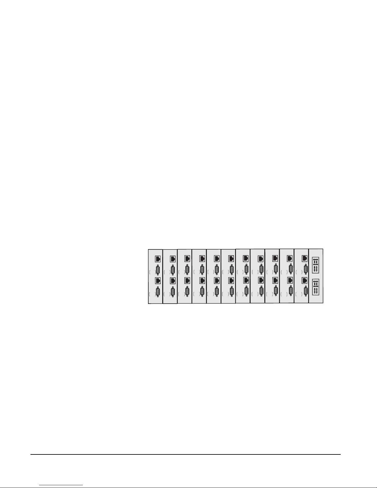
IMF-3 Interface Module Frame
The IMF-3 interface frame holds up to 11 interface modules in three rack units
(3 RU) of a standard Electronics Industry Association 19-inch wide (48.26 cm)
rack. The frame holds a modular, rear-mounted connector panel for each
interface, containing two RJ-45 connectors for connecting cable to matrix ports,
and two DB-9 connectors for connecting cable to non-4-wire devices. Figure
2-1illustrates the rear panel of an IMF-3 interface frame, with 11 rear-panel
assemblies installed.
The frame uses an external PSU-101 rack-mounted power supply to supply
power to the interface modules. A second PSU-101 can be attached for
redundancy.
Figure 2-1: IMF-3 Interface Frame Rear Panel
Note: The IMF-3 frame has an individual rear panel for each interface. All interfaces
use the same rear panel; however the use of the rear-panel connectors will vary with
the type of interface.
Each interface features indicators and controls that must be accessible to
operators, so put the interface module frame(s) in a convenient location. Usually
interface module frames are located near the matrix frame, but they can be
located farther away. The maximum distance between the matrix frame and the
interface frame is 500 feet (150 meters).
Each Eclipse frame contains its own power supplies and does not supply any
power for interfaces. A separate power supply (PSU-101) is only necessary for
interfaces mounted in IMF-3 frames. If redundant power supply pairs are used
for interfaces, mount them together. For detailed information on power supply
requirements, refer to Chapter 3, “Powering System Components.”
CH. A
Matrix
CH. A
I/O
CH. B
Matrix
CH. B
I/O
PHONE
LINE A
PHONE
LINE B
CH. A
Matrix
CH. A
I/O
CH. B
Matrix
CH. B
I/O
PHONE
LINE A
PHONE
LINE B
CH. A
Matrix
CH. A
I/O
CH. B
Matrix
CH. B
I/O
PHONE
LINE A
PHONE
LINE B
CH. A
Matrix
CH. A
I/O
CH. B
Matrix
CH. B
I/O
PHONE
LINE A
PHONE
LINE B
CH. A
Matrix
CH. A
I/O
CH. B
Matrix
CH. B
I/O
PHONE
LINE A
PHONE
LINE B
CH. A
Matrix
CH. A
I/O
CH. B
Matrix
CH. B
I/O
PHONE
LINE A
PHONE
LINE B
CH. A
Matrix
CH. A
I/O
CH. B
Matrix
CH. B
I/O
PHONE
LINE A
PHONE
LINE B
CH. A
Matrix
CH. A
I/O
CH. B
Matrix
CH. B
I/O
PHONE
LINE A
PHONE
LINE B
CH. A
Matrix
CH. A
I/O
CH. B
Matrix
CH. B
I/O
PHONE
LINE A
PHONE
LINE B
CH. A
Matrix
CH. A
I/O
CH. B
Matrix
CH. B
I/O
PHONE
LINE A
PHONE
LINE B
CH. A
Matrix
CH. A
I/O
CH. B
Matrix
CH. B
I/O
PHONE
LINE A
PHONE
LINE B
POWER SUPPLY #1
POWER SUPPLY #2
Page 18
INSTALLATION OVERVIEW
2-4
It is required that you leave an extra rack unit (1.75 in. or 44.45 mm) above and
below each external power supply unit. This allows for needed cooling for larger
system loads.
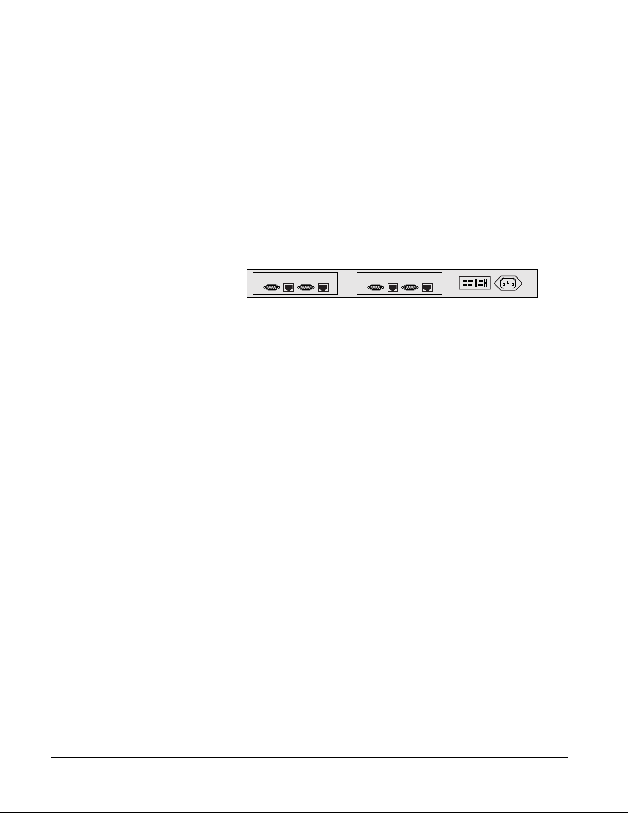
IMF-102 Interface Module Frame
The IMF-102 interface frame has slots for two interface modules in one rack unit
(1 RU) of a standard Electronics Industry Association 19-inch wide (48.26 cm)
rack.
It has an internal power supply and a connector for a redundant power supply. Its
rear input/output connector panel has two RJ-45 connectors and DB-9
connectors for each of the two interface modules. Figure 2-2 illustrates the rear
panel of an IMF-102 interface frame, with two installed rear-panel assemblies.
Figure 2-2: IMF-102 Interface Frame Rear Panel
DIF-102 Interface Module Frame
The DIF-102 interface frame has slots for two digital DIG-2 interface modules
in one rack unit (1 RU) of a standard Electronics Industry Association 19-inch
(48.26 cm) rack. DIG-2 interface modules allow the matrix to connect to digital
versions of Clear-Com intercom stations.
The DIF-102 frame is powered by one or two (for redundancy) external AC
mains to 24 VDC power supplies via locking DIN connectors on the DIF-102
rear panel. All other voltages are derived directly or indirectly from the 24 VDC
on the DIG-2 front and rear cards.
The DIF-102 should be located in the same building as the Eclipse frame. It can
be located up to 3000 feet (1000 meters) from an Eclipse frame.
INTERCOM PANELS AND EXPANSION PANELS
Locate all intercom panels at comfortable heights for operation. Leave at least 2
inches (50.8 mm) of clearance behind the panel chassis to allow for cable
connectors. In some low-light conditions, the front-panel display for the
ICS-2003 may be too bright. Refer to the ICS-2003 manual for “display
brightness adjustment.”
Accessory panels such as the XPL, AP, or EXP that are intended to expand or
enhance the operation of stations are usually mounted just above or below the
station with which they are associated. They can be located up to 25 ft. (7.62 m)
away from the station. A 6-ft. (1.8 m) cable is supplied to connect them.
Expansion panels such as the V12LDE, V12PDE, PD4203, PD4206, PD4230
and PD4230V may be mounted as required.
Panels should not be more than 3,000 ft. (1000 m) from the Eclipse matrix
frame to which they are connected.
CH.A
Marix
CH.A
I/O
CH.B
Matrix
CH.B
I/O
CH.A
Marix
CH.A
I/O
CH.B
Matrix
CH.B
I/O
Page 19

INSTALLATION OVERVIEW
2-5
EXTERNAL COMPUTER
The Eclipse Configuration System (ECS) runs on an external computer that
connects to the matrix frame via a standard PC serial port to a DB-9 RS-232
connector. The maximum recommended length of the cable is approximately 10
feet (3.04 meters).
Note: If your computer does not have a serial port, but only offers USB, adapters are
available from computer parts suppliers.
You can also run ECS on an Ethernet network connected to the frame through
the two standard RJ-45 Ethernet connectors labeled LAN 1 and LAN 2.
Ethernet connection allows single or multiple PCs on the network to control,
configure, monitor, and diagnose single or multiple matrices.
Page 20

INSTALLATION OVERVIEW
2-6
Page 21

INSTALLATION OVERVIEW
3-1
POWERING SYSTEM COMPONENTS
POWER REQUIREMENTS
Power requirements differ for each component of an Eclipse system. This chapter
gives guidelines for providing power to the following components:
•Matrices
• i-Series intercom panels
• ICS-2003/ICS-1016 intercom panels
• ICS-52/62/92/102 intercom panels
• XPL-12/22 display expansion panels and AP-22 assignment panels
• 4000 Series II panels
•V-Series panels
• Interface frames
MATRICES
Electrical power for an Eclipse Omega, Median or Pico matrix or for an
Eclipse-32 matrix originates from AC mains line current, which in turn provides
power to the matrix’s internal DC power supplies. Each matrix is equipped with
two power supplies that can be connected to separate branches of AC mains,
providing redundancy for the power supplies and the power sources.
If an AC power source shuts off for any reason, a matrix can continue to operate
from the second AC power source. If one power supply fails, a matrix can
continue to operate from the second supply.
If one of the two DC power supplies fails, an “alarm” failure condition will
activate to provide you with an opportunity to repair or replace the supply while
the second supply powers the system.
Eclipse Omega Matrix
The Eclipse Omega matrix has two internal, Euro Cassette, plug-in power
supplies. Each of the power supplies must be connected to a dedicated branch of
AC mains power. The matrix will continue to operate even if one of the AC
power branches fails.
Clear-Com ships each matrix with two power supplies already installed. When
you receive the matrix, connect each of the power supplies to a dedicated branch
of AC mains power using the IEC power connectors on the Eclipse Omega
frame’s rear panel.
A fully equipped Eclipse Omega frame requires 100 to 240 VAC at 50 to 60 Hz
with a maximum dissipation of 400 W.
Each matrix is equipped
with two power supplies that
can be connected to
separate branches of AC
mains, providing redundancy
for the power supplies and
the power sources.
3
Page 22

INSTALLATION OVERVIEW
3-2
Eclipse Median Matrix
The Eclipse Median matrix has two internal, Euro Cassette, plug-in power
supplies. Each of the power supplies must be connected to a dedicated branch of
AC mains power. The matrix will continue to operate even if one of the AC
power branches fails.
Clear-Com ships each matrix with two power supplies already installed. When
you receive the matrix, connect each of the power supplies to a dedicated branch
of AC mains power using the IEC power connectors on the Eclipse Median
frame’s rear panel.
A fully equipped Eclipse Median frame requires 100 to 240 VAC at 50 to 60 Hz
with a maximum dissipation of 400 W.
Eclipse Pico Matrix
The Eclipse Pico matrix has two internal power supply units. One power supply
unit can power an entire matrix; the second unit provides a backup in case of an
equipment failure.
In addition, the two supplies have separate IEC connectors to AC mains power,
and are designed for completely automatic and transparent changeover between
supplies in the event of an outage on one of the AC mains circuits.
The power supplies are “universal,” operating over a voltage range of 100 to 240
VAC at 50 to 60 Hz with a maximum dissipation of 500W.
Eclipse-32 Matrix
The Eclipse-32 matrix has two internal power supply units. One power supply
unit can power an entire matrix; the second unit provides a backup in case of an
equipment failure.
In addition, the two supplies have separate IEC connectors to AC mains power,
and are designed for completely automatic and transparent changeover between
supplies in the event of an outage on one of the AC mains circuits.
The power supplies are “universal,” operating over a voltage range of 100 to 240
VAC at 50 to 60 Hz.
INTERCOM PANELS
i-Series Intercom Panels
Each i-Station has an internal power supply, with a removable AC power cord.
The power supply is “universal,” operating over a voltage range of 90 to 245 VAC
and 50 to 60 Hz. The maximum dissipation is 40 W.
ICS-2003 Intercom Panels
Each ICS-2003 intercom station has a separate external DC power supply. The
power supply is “universal,” operating over a voltage range of 90 to 260 VAC at
45 to 65 Hz. The maximum dissipation is 30 W.
Page 23

INSTALLATION OVERVIEW
3-3
ICS-52/62/92/102 Intercom Panels
Each ICS-52/62/92/102 intercom station is powered by a transformer that runs
off of AC mains power: the 120-V transformer requires a two-conductor wall
outlet, and is housed in a 2 x 2 x 3 in. (5 x 5 x 7.6 cm) direct plug-in module; the
240-V transformer requires a three-conductor wall outlet, and is housed in a 2 x
3 x 5 in. (5 x 7.6 x 12.7 cm) box located in the middle of its cable’s length. Each
transformer connects to each compact station with the 2.1 mm coaxial power
connector on the rear of the station.
An ICS-102/92/62/52 intercom station requires 90 to 125 or 210 to 250 VAC at
45 to 65 Hz with a maximum dissipation of 40 W.
XPL-12/22 Display Expansion Panels and AP-22 Assignment Panels
XPL-12/22 display expansion panels and AP-type assignment panels require an
external transformer identical to those used with the 1 RU stations (90 to 125 or
210 to 250 VAC at 45 to 65 Hz with a maximum dissipation of 40 W).
4000 Series II Panels and Expansion Panels
Each 4000 Series II panel or expansion panel has a separate external DC power
supply. The power supply is “universal,” operating over a voltage range of 100 to
240 VAC at 50 to 60 Hz. The maximum dissipation is 30 W.
V-Series Panels and Expansion Panels
Each V-Series panel or expansion panel has a separate external DC power supply.
The power supply is “universal,” operating over a voltage range of 100 to 240
VAC at 50 to 60 Hz. The maximum dissipation is 50 W.
INTERFACE MODULE FRAME POWER SUPPLY REQUIREMENTS
IMF-3 Interface Module Frame
As a rule-of-thumb, one PSU-101 power supply unit is required for every two
IMF-3 frames. There are two exceptions to this rule. The first exception occurs
when the frames have a large number of CCI-22 party-line interfaces which
require no DC power from the IMF-3 frame. However, an IMF-3 with only
CCI-22 interfaces still needs to be connected to a PSU-101 as the IMF frame
itself needs some DC power for the circuitry on its rear panel.
The second exception occurs when using multiple TEL-14 telephone interfaces.
An IMF-3 interface frame will only power eight TEL-14 interfaces. If more
TEL-14 interfaces are required, you must install them in a second IMF-3 frame
with a second power supply.
A PSU-101 requires 90 to 260 VAC at 45 to 65 Hz with a maximum dissipation
of 80 W. A PSU-101 connected for redundancy requires very little AC current
unless it is used.
An audible alarm is included in the PSU-101, and an additional set of
alarm-relay contacts are provided on the supply. Clear-Com recommends that
these contacts be connected to the external alarm input of the matrix frames. If
For more information on
interface frames, refer to
the Interface Frames
Instruction Manual.
Page 24

INSTALLATION OVERVIEW
3-4
any of the power supplies in the PSU-101 fails, it would cause a system alarm.
LEDs on the front of the PSU-101s will indicate the failure.
Installing two PSU-101 power supplies per application provides redundancy
because either of the two PSU-101 power supplies can power a complete system.
If one fails, it can be removed without interruption of the entire system. Rear
panel connectors provide easy parallel connection to the IMF-3 Interface Module
Frame.
The current capacities of the power supplies are as follows:
• 9 V analog 3.0 A
• -9 V analog 3.0 A
The following chart provides the current drain of the +/- analog power supplies
for all components in the system. Some devices, such as interfaces, have a varying
current depending on the operation of features. In applications where it is
possible to activate all operating features of all components used, use the
maximum current column for planning.
Table 3-1: Interface Current Consumption
Figure 3-3 shows the PSU-101 to IMF-3 wiring possibilities.
Component
Average
Current
Maximum
IMF-3 Frame 0.20 A 0.20 A
CCI-22 0.00 A 0.00 A
FOR-22 0.07 A 0.15 A
TEL-14 0.28 A 0.37 A
RLY-6 0.10 A 0.15 A
GPI-6 0.02 A 0.02 A
Page 25

INSTALLATION OVERVIEW
3-5
Figure 3-3: PSU-101 to IMF-3 Wiring
IMF-102 Interface Module Frame
The IMF-102 interface frame has an internal power supply and a rear-panel
connector to provide redundant power. The IMF-102 requires 90 to 250 VAC
with a maximum dissipation of 20 watts.
DIF-102 Interface Module Frame
The DIF-102 interface frame is powered by one or two (for redundancy) external
AC mains to 24 VDC power supplies via locking DIN connectors on the
DIF-102 rear panel. All other voltages are derived directly or indirectly from the
input 24 VDC on the DIG-2 front and rear cards.
The DIF-102 frame has a PSU fail-alarm output provided by Form C relay
change-over contacts made available on a 9-way make D connector on the
DIF-102 rear panel.
PSU-101
IMF-3
IMF-3
IMF-3
IMF-3
IMF-3
PSU-101
PSU-101
Page 26

INSTALLATION OVERVIEW
3-6
Page 27

INSTALLATION OVERVIEW
4-1
WIRING SYSTEM COMPONENTS
SUMMARY OF WIRING SYSTEMS
This chapter describes how to connect an Eclipse matrix to its remote panels and
interfaces. Most panels and interfaces connect to a matrix via single 4-pair
shielded RJ-45 terminated cables.
For more detail about component placement, specifications of individual
products, and internal adjustments, refer to the individual manual for each
product. To configure panels and interfaces, refer the Eclipse Configuration System
(ECS) Manual.
The following wiring topics are discussed:
• Wiring RJ-45 cables.
• Wiring an Eclipse matrix to an external computer, to a local area network, to
analog and digital intercom stations, to general-purpose outputs, to
general-purpose inputs, to an external alarm, and directly to a 4-wire audio
device.
• Wiring an Eclipse matrix to the following interfaces: FOR-22 interface,
CCI-22 interface, TEL-14 interface, RLY-6 interface, and GPI-6 interface.
• Wiring an Eclipse station miscellaneous connector.
• Wiring an OPT-100 auxiliary audio I/O option connector.
• Wiring an Eclipse panel accessory connector.
Note: Single-pair digital wiring requires double-shielded 24 AWG conductor
CAT-6E enhanced STP cable.This wiring is discussed only in general in this manual.
For more detailed instructions, refer to the individual manual for each product.
RJ-45 CABLES
The following section discusses the use of RJ-45 connectors for connecting an
Eclipse frame to panels and interfaces. It includes the following topics:
• General discussion about RJ-45 connector cables
• Clear-Com kits and recommendation
• Installing RJ-45 connectors.
General Discussion About RJ-45 Connector Cables
The system wiring is with shielded CAT5 twisted cable with RJ-45 connectors
on either end; however, there are various methods available to deliver these cables
from one place to another.
All Eclipse matrix panels have built-in RJ-45 connectors. Direct 4-pair cable with
RJ-45 connectors on either end can connect an Eclipse matrix port to an
individual panel.
4
Page 28

INSTALLATION OVERVIEW
4-2
Shielded CAT5 cables are available with RJ-45 terminations already installed.
Bulk RJ-45 connectors can be bought and installed on custom length cables.
The term “category 5” (CAT5) refers to a communications cable standard that
calls out transmission characteristics of twisted-pair cables for data
communication use. For each increasing “category” (CAT) number the
guaranteed bandwidth for data communication purposes is higher.
For the 4-pair wiring scheme between the frame panels, Eclipse uses the AT&T
T568B wiring standard for data cables. Cables for use with Ethernet 10-BASE-T
are of this type. Cables are available in solid or stranded wire in #24 or #26
AWG .
Clear-Com Kits and Recommendation
There are at least five different wiring standards that use the RJ-45 connector.
Although they look identical, many pre-made cables and utility items, like
couplers, will not work properly. You must know what wiring standard is used in
accessories that you buy.
Note: Long runs with flat cable are not acceptable. The data and audio pairs are not
twisted, therefore the crosstalk within the cable is high.
The T568B standard is a mature, well supported standard that allows many
advantages. Fast easy termination of cables as well as the availability of a vast
array of wiring adapters and patching systems allow great versatility for all
applications of intercom wiring. RJ-45 connectors are easy and fast to connect to
equipment. T568A cables differ only on the color of the insulation on pairs 2
and 3. If you are not cutting the ends off pre-made cable, you do not need to
worry about it. Be aware that if you do remove the ends from pre-made cable to
shorten or to punch onto blocks, pair 2 and 3 colors may be different.
Caution: Make sure the type of RJ-45 connector matches your wire type. Connectors
are available for both stranded and solid wire. Clear-Com intercom stations do not
require keyed connectors. Please refer to the following list for connector vendor and
port numbers.
Clear-Com recommends that you thoroughly test all cables before connecting
them.
The following products are recommended as possible sources for cables,
connectors and tools:
• Crimper—Siemon PT908 or AMP 2-231652-1 with 853400-1 dies
• Stripper—Siemon CPT
•Tester—Siemon STM-8
• Connector RJ-45 Shielded 26-22 AWG Stranded or Solid RJ-45—Siemon
PS-8-8
Installing RJ-45 Connectors
RJ-45 connectors can be a challenge to install correctly unless some of the
following techniques are followed. Like most wiring skills, once you know the
Page 29

INSTALLATION OVERVIEW
4-3
“tricks,” it’s fairly easy. It is very strongly suggested that you test your work with a
cable checker.
The technique that will transform this task from tedious to easy is described next.
If you understand it, you can skip reading the rest of the detailed steps. The main
hurdle in putting these connectors on correctly is the tendency of the wires to slip
out of the correct order as you slide the prepared cable end into the connector. To
avoid this problem, try this:
1. Strip enough jacket off the cable to allow you to grasp the wires and pull the
jacket back.
2. Untwist the wires and pull them into the correct order and let the jacket slip
back to hold them in place.
If you have done it correctly, the wires will stay in the correct order. Trim exposed
wires to about 9/16 in. (14.28mm) and install into the connector. If this is clear
you won’t need to read the step-by-step instructions that follow.
1. Strip off enough of the outside vinyl jacket to allow you to grip the wires
inside easily (2 in. or 50.8 mm). While holding the four twisted pairs in one
hand, slide back the vinyl jacket and clamp it between your thumb and
forefinger. Keep the jacket clamped in this retracted position until the fourth
step.
2. Pull the twisted pairs to the one side and untwist them back to the edge of the
vinyl jacket. Smooth the kinks out slightly by pulling the conductors through
your fingers.
3. In the correct color sequence, pull one wire at a time, straight out, clamping it
in place between your thumb and forefinger. If a wire must cross the others,
make sure it does it inside the jacket. Make sure your color sequence matches
the other side and it does not reverse. If you are rebutting a cable, verify color
code. The twisted pairs must be positioned correctly.
4. While holding the wires in the correct order, release your clamped thumb and
forefinger enough to allow the retracted jacket to slip back. You still need to
maintain enough pressure on your thumb and forefinger to hold the jacket
and wires flat but the individual wires should stay in the correct order without
holding them with your other hand.
5. Cut the exposed wires to the correct length and slip them into the RJ-45
connector as you release your clamped thumb and forefinger. Crimp and test
the cable.
6. Care must be exercised that the shield is not left pulled back inside the wire
jacket. We also recommend that the drain wire is soldered to the side of a
shielded style connector. Our tests show that a drain wire that is only crimped
and not soldered will make an intermittent connection at best.
Page 30

INSTALLATION OVERVIEW
4-4
WIRING THE MATRIX TO A COMPUTER
WIRING FOR SERIAL CONNECTION
The DB-9F connector labeled “RS-232” on the rear of an Eclipse-208 matrix, or
the DB-9F connector labeled “PC” on the front of an Eclipse-32 matrix,
connects the matrix to an external computer. The computer runs the Eclipse
Configuration System (ECS) program. To configure the serial port, refer to the
Eclipse Configuration System Instruction Manual.
To connect a computer to the matrix, run cable from the matrix’s DB-9
connector to the computer’s serial port. The maximum recommended length of
the cable is approximately 10 feet (3 meters).
A computer has either a 9-pin serial port or a 25-pin serial port. Figure 4-4
shows the wiring for a 25-pin port. Figure 4-5 shows the wiring for a 9-pin port.
Note: If your computer does not have a serial port, and only offers USB, adaptors are
generally available from computer parts suppliers.
Figure 4-4: Computer DB-25, RS-232 Cable
1
2
20
19
18
17
16
15
14
8
7
6
5
4
3
21
11
22
12
23
10
9
25
24
13
1
2
9
8
7
6
5
4
3
Computer Serial Port
DB-25F Cable Connector
Eclipse Matrix
“RS-232” DB-9M Cable Connecto
r
Transmit (TXD)
Transmit (TXD)
Receive (RXD)
Receive (RXD)
Ground (GND)
Page 31

INSTALLATION OVERVIEW
4-5
Figure 4-5: Computer DB-9, RS-232 Cable
WIRING FOR ETHERNET CONNECTION
To connect the matrix to a local-area network (LAN), use the RJ-45 sockets
labeled “LAN 1” and “LAN 2” on the rear of the Eclipse-208 matrix, or the
RJ-45 socket labeled “LAN” on the rear of the Eclipse-32 matrix. The connectors
have standard Ethernet pin assignments, shown in Figure 4-6.
Figure 4-6: Pin Assignments for LAN 1 and LAN 2 Connectors
WIRING THE MATRIX TO INTERCOM STATIONS/PANELS
Eclipse uses a 4-pair (analog) or single-pair (digital) wiring scheme between the
frame and stations. All Eclipse stations have built-in RJ-45 connectors.
4-PAIR ANALOG
Four-pair analog wiring is done with shielded CAT5 RJ-45 cable.
• Pair 1 transmits analog audio from the matrix to the station.
• Pair 2 transmits digital data from the station back to the matrix.
• Pair 3 transmits audio from the station to the matrix.
• Pair 4 transmits digital data from the matrix back to the station.
1
2
9
8
7
6
5
4
3
1
2
9
8
7
6
5
4
3
Computer Serial Port
DB-9F Cable Connector
Eclipse Matrix “RS-232”
DB-9M Cable Connector
Receive (RXD)
Transmit (TXD)
Transmit (TXD)
Receive (RXD)
Ground (GND)
8
7
6
5
4
3
2
1
LAN1 and LAN2
Ethernet RJ-45 Connectors
PIN
FUNCTION
1
2
3
4
5
6
7
8
Transmit data +
Transmit data
Receive data +
Unused
Unused
Receive data
Unused
Unused
Page 32

INSTALLATION OVERVIEW
4-6
Figure 4-7: Wiring Matrix to Analog Station Using RJ-45
RJ-45 CONNECTOR
AT MATRIX PORT
RJ-45 CONNECTOR ON
STATION OR INTERFACE
Matrix Frame RJ-45 Pin Numbers
Shielded category-5 cables wired pin-to-pin
Station RJ-45 Pin Numbers
Pair 2
Pair 1
Pair 3
Pair 4
RS-422 Input +
(into Matrix)
RS-422 Input
(into Matrix)
Audio Input +
(into Matrix)
Audio Output +
(from Matrix)
Audio Output
(from Matrix)
Audio Input
(into Matrix)
RS-422 Output +
(from Matrix)
RS-422 Output
(from Matrix)
1
2
3
5
6
7
1
2
6
7
8
4
3
4
5
8
RS-422 Output +
(from station)
RS-422 Output
(from station)
Audio Output +
(from station)
Audio Input +
(into station)
Audio Input
(into station)
Audio Output
(from station)
RS-422 Input +
(into station)
RS-422 Input
(into station)
Pair 1 Audio output from Matrix to station
Pair 2 RS-422 data input from station to Matrix
Pair 3 Audio input from station to Matrix
Pair 4 RS-422 data output from Matrix to station
8765
4
3
2
1
8
7
6
5
4
3
2
1
Views from
front of
connectors
Page 33

INSTALLATION OVERVIEW
4-7
SINGLE-PAIR DIGITAL
Single-pair digital wiring is accomplished with double-shielded 24 AWG
conductor CAT-6E enhanced STP cable. Pair 1 transmits and receives
multiplexed digital and analog between the matrix and the station.
Note: Ensure that the “select” switch on the station’s rear panel is in the correct
position for the intended use.
Figure 4-8: Wiring Matrix to Digital Station Using RJ-45
WIRING THE MATRIX TO GENERAL-PURPOSE
OUTPUTS
A general purpose output or “relay” is a switch that you control remotely. You
program the relay in the ECS configuration program to close a contact whenever
an intercom station’s key is pressed. When the contact is closed, it completes an
electronic circuit’s signal path so that a remote device, such as a light, is powered.
You can program a GPO to mute a speaker, to turn on an applause light, to turn
on a door lock, or to perform a variety of other functions. For example, if you
often need to get the attention of a station operator working in a high-noise
environment, such as a control booth, you can program a relay to switch on a
light at that station each time the station receives an incoming call, to ensure that
the station operator will not miss the call.
The male 25-pin D-type socket labeled “GP OUT” on the rear of the Eclipse
matrix connects to eight general-purpose outputs (GPOs). The general purpose
outputs are single-pole double-throw relays with contact ratings of 30 VDC
(volts direct current) at 1 ampere.
NOTE: If you use the GP-OUT port, you must fit the following filter between the
PROC-RCC socket and the cable:
CINCH FA-25PS/1 25W D-type in-line 1000pF filter
(UK supplier: Farnell 322-2676)
Pair 2
Pair 1
Pair 3
Pair 4
1
2
3
4
5
6
7
8
1
2
3
4
5
6
7
8
Matrix Frame End
ATT-T568B (Modular Jumpers Wired One to One)
Station En
d
No Connection (NC)
No Connection (NC)
No Connection (NC)
M
ultiplexed Data/Audio
M
ultiplexed Data/Audio
No Connection (NC)
No Connection (NC)
No Connection (NC)
Page 34

INSTALLATION OVERVIEW
4-8
Each general-purpose output has a relay inside the Eclipse-208 frame. When a
general-purpose output is inactive, the associated “common” pin on the GP
OUT connector will be shorted to the relevant “normally closed” pin. When a
general-purpose output becomes active, the short between the “common” pin is
broken and a new connection is made between the “common” pin and the
“normally open” pin.
Figure 4-9 shows the pin configuration of the general-purpose outputs
connector.
Figure 4-9: Pin Configuration of the General-Purpose Outputs Connector
1
2
3
4
5
6
7
8
9
10
11
12
13
14
15
16
17
18
19
20
21
22
23
24
25
Digital Ground
PIN
DESCRIPTION
1
2
3
4
RELAY 1 Common
RELAY 1 Normally Closed
RELAY 1 Normally Open
RELAY 2 Common
RELAY 2 Normally Closed
RELAY 2 Normally Open
RELAY 3 Common
RELAY 3 Normally Closed
RELAY 3 Normally Open
30 VDC at 1 Ampere
Common
Normally Open
Normally Closed
Common
Normally Open
Normally Closed
Common
Normally Open
Normally Closed
Common
Normally Open
Normally Closed
Common
Normally Open
Normally Closed
Common
Normally Open
Normally Closed
Common
Normally Open
Normally Closed
Common
Normally Open
Normally Closed
RELAY 1
RELAY 2
RELAY 3
RELAY 4
RELAY 5
RELAY 6
RELAY 7
RELAY 8
RELAY 4 Common
RELAY 4 Normally Closed
RELAY 4 Normally Open
GROUND
RELAY 5 Common
RELAY 5 Normally Closed
RELAY 5 Normally Open
RELAY 6 Common
RELAY 6 Normally Closed
5
6
7
8
9
10
11
12
13
14
16
17
18
19
20
21
22
23
24
25
15
RELAY 6 Normally Open
RELAY 7 Common
RELAY 7 Normally Open
RELAY 7 Normally Closed
RELAY 8 Common
RELAY 8 Normally Closed
RELAY 8 Normally Open
DB-25 Male Connector
Page 35

INSTALLATION OVERVIEW
4-9
WIRING THE MATRIX TO GENERAL-PURPOSE
INPUTS
You can connect an external logic device—such as an external foot switch, a
panel-mounted switch, or the logic output of some other device—to the
connector labeled “GP IN” on the rear of the Eclipse matrix. When the external
logic device is activated, it sends a control signal into the matrix to perform one
of several preset functions, such as turning an intercom station’s microphone on
or off, muting a microphone’s output, or turning a station’s speaker off. You
choose the function to perform and the station upon which it is performed from
the Eclipse Configuration System.
The DB-25 connector labeled “GP IN” on the rear of the Eclipse matrix
connects to eight local general-purpose inputs. Figure 4-10 shows the pin
assignments of the Eclipse general-purpose inputs connector.
Figure 4-10: Pin Configuration of the General-Purpose Inputs Connector
The general-purpose inputs operate in one of two modes: the “opto-isolated”
mode or the unisolated mode. The opto-isolated mode requires the externally
connected equipment to provide the current to power the general-purpose input.
The non-isolated mode does not require that the externally connected equipment
powers the general-purpose input. A voltage output on the GP IN connector
supplies the current.
1
2
3
4
5
6
7
8
9
10
11
12
13
14
15
16
17
18
19
20
21
22
23
24
25
PIN
DESCRIPTION
1
2
3
4
Logic Input 1
Logic Input 3
Logic Input 5
Logic Input 7
N/A
N/A
N/A
N/A
Ground
Ground
Ground
Ground
Logic Input 2
Logic Input 4
Logic Input 6
Logic Input 8
N/A
5
6
7
8
9
10
11
12
13
14
16
17
18
19
20
21
22
23
24
25
15
N/A
N/A
N/A
Voltage In+
Voltage In+
Voltage In–
Voltage In–
DB-25 Female Connector
Logic Input 1
Logic Input 2
Logic Input 3
Logic Input 4
Logic Input 5
Logic Input 6
Logic Input 7
Logic Input 8
Ground
Ground
Ground
Ground
Ground
V IN+
V IN+
V IN–
V IN–
Ground
Page 36

INSTALLATION OVERVIEW
4-10
To select a mode, move the J1 jumper on the CPU rear card to one of two
positions. (The J1 jumper is located on the inner-frame side of the DB-25
connector.)
• For opto-isolated mode, fit the J1 jumper across pins 1 and 2.
• For non-isolated mode, fit the J1 jumper across pins 2 and 3.
NOTE: It is recommended that you set the connector to the fully opto-isolated mode.
OPTO-ISOLATED MODE
Figure 4-11 shows the opto-isolated connection.
Figure 4-11: Opto-Isolated Connection to Eclipse GPI Connector
In this mode, a DC voltage of between 7 and 24 volts is required at the
EXTVIN+ pin with relation to the EXTVIN– pin. To cause an input to detect
an active signal, you must send current from the relevant input pin.
The external device should draw no current to cause an inactive input and at least
5 mA to cause an active input. The opto-isolator drive line contains a 1.5 kOhm
resistor to limit the current through the opto-isolator. You can therefore connect
the input pins directly to the EXTVIN– level to cause an active input.
The voltage level at the external input pin should not be allowed to go below
EXTVIN– or above +6 V with respect to EXTVIN–.
NON-ISOLATED MODE
Figure 4-12 shows the non-isolated connection.
Figure 4-12: Non-Isolated Connection to Eclipse GPI Connector
To cause an input to detect an active signal, you must send current from the
relevant input pin.
+
C
10uF_10V
D
BYG22D
+
C
10uF_25V
INPUT 1EXTVIN-
EXTERNAL INPUT 2
EXTVIN+
INPUT 2
R29 1.5K
U
LM78L05ACM
VIN8VOUT
1
7-24V
R30 1.5K
U
MOCD207-M
1
3
2
4
8
7
6
5
EXTERNAL INPUT 1
R
33K2
+3V3
R
33K2
+3V3
INPUT 1
EXTERNAL INPUT 2
INPUT 2
R29 1.5K
R30 1.5K
U
MOCD207-M
1
3
2
4
8
7
6
5
EXTERNAL INPUT 1
R
33K2
+3V3
R
33K2
+3V3
+3V3
Page 37

INSTALLATION OVERVIEW
4-11
The external device should draw no current to cause an inactive input and at least
5 mA to cause an active input. The opto-isolator drive line contains a 1.5 kOhm
resistor to limit the current through the opto-isolator. You can therefore connect
the input pins directly to a ground pin to cause an active input.
The voltage level at the external input pin should not be allowed to go below
ground or above +6 with respect to ground.
WIRING THE MATRIX TO AN EXTERNAL ALARM
With the Alarm I/O DB-9F connector, you can connect an external alarm device
to monitor failures in the matrix. Pins are also available for connecting an
external alarm source to the matrix’s Alarm System. For details on the functions
that are monitored by the Alarm System refer to the Eclipse-208 or Eclipse-32
Manuals.
A failure will activate the relay contacts connected to pins 4, 5, and 9 of the
connector. These contacts are “dry,” and are rated at 1 A at 24 VDC. They are
not recommended for AC mains line current.
Pins are provided for adding an additional alarm source to the matrix’s alarm
system. Pin 6 is an alarm input to the Eclipse matrix. It is connected to the input
of a 3.3 volt logic device. A logic high on this input will cause the Eclipse matrix
to detect an alarm condition. A logic low or an open circuit will cause the Eclipse
matrix to detect no alarm condition.
Pin 1 is a voltage source out of the Eclipse matrix. It is connected through a 10k
ohm pull-up resistor to the +5 volt supply rail inside the Eclipse matrix.
A contact closure placed across pins 1 and 6 will also cause an alarm condition.
The alarm outputs of the PSU-101 could be wired directly to these pins allowing
the CPU card to report PSU failures also.
Figure 4-13: Alarm I/O Connector
1
2
9
8
7
6
5
4
3
1
2
3
4
Relay Normally Closed
Relay Wiper
Relay Normally Open
To Alar
m
To Alar
m
System 200/COM-72
"Alarm I/O" DB-9F
Connector
PSU-101
"Alarm Relay"
Connector
Page 38

INSTALLATION OVERVIEW
4-12
WIRING THE MATRIX DIRECTLY TO A 4-WIRE
AUDIO DEVICE
An external 4-wire audio device can be directly connected to a port connector
through the four audio pins, as shown in Figure . If there is excessive noise on the
lines between this device and the matrix, the device may be electronically
unbalanced with the rest of the system. The device will need to be isolated with
external isolation transformers.
The “CALL SEND” output can be connected to the “CALL REC” input to tell
the system software that this is a directly connected port.
The Eclipse Configuration System allows the changing of the audio output
reference level between -24, -21, -18, -15, -12, -9, -6, -3, 0, +3, +6, +9, +12, +14
dB. With a +12dB output reference level, it is possible to drive a 200 to 400
Ohm headset directly with a port output for such uses as direct IFB feed.
The Eclipse Configuration System allows the changing of the audio input
reference level between -12, -9, -6, -3, 0, +3, +6, +9, +11 dB.
Figure 4-14: Direct Eclipse Matrix Port Connection
WIRING THE MATRIX TO INTERFACE MODULES
Interface modules convert the 4-wire signals of a central matrix port to some
other form of communication, such as telephones, camera intercoms, two-way
radios, and so on. In this way, non-4-wire devices can communicate with the
central matrix.
Each interface module has hardware connectors to connect to both the central
matrix and to the external device that communicates with the central matrix.
To house these interface modules, Clear-Com offers three types of interface
frames.
•The IMF-3 interface frame holds up to 11 interface modules in 3 RU of rack
space. Modular rear-mounted connector panels hold two RJ-45 connectors to
the matrix ports and two DB-9’s attaching the connected devices. The frame
uses an external PSU-101 rack-mounted power supply to supply power to the
interface modules. A second PSU-101 can be attached for redundancy.
Note: The IMF-3 frame has an individual rear panel for each interface. All interfaces
use the same rear panel, however the use of the rear-panel connectors will vary with
the type of interface.
Call Receive +
Call Receive -
A
udio Receive +
Audio Send +
Audio Send -
Audio Receive -
Call Send +
Call Send -
1
2
3
4
5
6
7
8
Output
Input
1 2 3 4 5 6 7 8
Rear View of
Connector
Page 39

INSTALLATION OVERVIEW
4-13
•The IMF-102 interface frame has slots for two interface modules in 1 RU of
rack space. Its rear input/output connector panel has two RJ-45 connectors
and DB-9 connectors for each of the two interface modules. It has an internal
power supply and a connector for a redundant power supply.
•The DIF-102 interface frame has slots for two digital DIG-2 interface
modules in 1 RU of rack space. DIG-2 interface modules allow the matrix to
connect to digital versions of Clear-Com intercom stations. The DIF-102
frame is powered by one or two (for redundancy) external AC mains to 24
VDC power supplies via locking DIN connectors on the rear panel. All other
voltages are derived directly or indirectly from the 24 VDC on a DIG-2
interface module’s front and rear cards.
CCI-22 and FOR-22—The CCI-22 and FOR-22 dual audio interfaces use each
of the RJ-45 connectors on its rear panel for connection to the matrix port. The
top RJ-45 is for the first channel of the interface. The lower RJ-45 is for the
second channel. The DB-9Ms are the interface’s audio and control inputs and
outputs. Refer to the section on those interfaces later in this chapter for wiring
details.
TEL-14—The TEL-14 interface is a two-channel device and uses each of the
RJ-45 connectors on its rear panel for connection to the matrix port. The top
RJ-45 is for Line A of the interface and the lower RJ-45 is for Line B of the
interface. The upper and lower DB-9M connectors are the Line A and Line B
connections to the telephone line. Clear-Com provides DB-9F to RJ-11 adapters
so that standard phone line RJ-11 plugs and jacks can connect directly to the
interface. Refer to the section on this interface later in this chapter for wiring
details.
Each audio interface has internal ID circuit jumpers that will identify to the
matrix port cards the type of interface it is; as a result the ports and interface
modules can be moved without having to change the wiring.
RLY-6 and GPI-6—The RLY-6 and GPI-6 use the same RJ-45s, however their
function and connection is different. These interfaces are daisy chained in their
direct connection to the matrix frame. RLYs and GPIs do not require connection
to a system “port.” The first RLY or GPI interface has its RJ-45 connected to the
special RJ-45 on the rear panel of the frame marked GPI/RLY Interface. The top
connector of the second RLY or GPI interface connects to the bottom RJ-45 of
the first. Each successive interface is connected in this daisy-chained fashion.
Page 40

INSTALLATION OVERVIEW
4-14
Figure 4-15 shows the rear panel of a IMF-3 wired for RLY-6s and GPI-6s. The
CPU card will read these modules and will call the first RLY-6 relays 1 to 6. The
second RLY-6 will be identified as relays 7 to 12.
Figure 4-15: RLY-6/GPI-6 Daisy Chain Connection
Figure 4-16 shows the pin assignments of RJ-45 connectors when used to
connect to interfaces (IMF-3 frames).
Figure 4-16: Matrix Frame to IMF-3 Interface Connection
FOR-22 4-WIRE/RADIO INTERFACE WIRING
The FOR-22 4-wire/radio interface connects two external 4-wire circuits to the
matrix. Camera intercoms, two-way radios, microwave and satellite links, IFBs,
and program audio in and out are candidates for use with the FOR-22.
A FOR-22 interface connects to an Eclipse matrix through the two RJ-45
connectors on the IMF-3 or IMF-102 rear panel assembly to which the FOR-22
is connected. One RJ-45 connector is for the first channel of the interface. The
second RJ-45 connector is for the second channel.
The user side of the FOR-22 for each channel appears on a DB-9M connector
on the rear of the IMF-3 for IMF-102 frame. Figure 4-17 shows the pinout of
either one of these connectors. Each channel is identical.
Ports
Rear View of IMF-3 Frame
GPI/RLY
Interface
Connector
RJ-45 RJ-45 RJ-45 RJ-45 RJ-45
DB-9 DB-9 DB-9 DB-9 DB-9
RJ-45 RJ-45 RJ-45 RJ-45 RJ-45
DB-9 DB-9 DB-9 DB-9 DB-9
Other
Interfaces
GPI-6
#2
RLY-6
#2
RLY-6
#1
GPI-6
#1
1
2
3
4
5
6
7
8
Matrix Frame End
Call Receive +
Call Receive -
A
udio Receive +
Audio Send +
Audio Send -
Audio Receive -
Call Send +
Call Send -
Call Send +
Call Send -
Audio Send +
Audio Receive +
Audio Receive -
Audio Send -
Call Receive +
Call Receive -
Interface End
Pair 2
Pair 1
Pair 3
Pair 4
Interface Wiring
1
2
3
4
5
6
7
8
Page 41

INSTALLATION OVERVIEW
4-15
Figure 4-17: Pinout of the DB-9M I/O Connectors for FOR-22s
The following sections describe how to wire for the various type of inputs and
outputs available on this connector:
• External audio devices
• Call signal input
• Relay contacts.
External Audio Devices
Connect external audio devices to the FOR-22 ports through the two DB-9M
connectors labeled “I/O” on the rear panel. Both audio input and output are
transformer isolated. For more information on the various level ranges available
on the input and output refer to the FOR-22 manual.
Call Signal Input
The Call Signal input is used to receive a call/logic input signal from an external
device and send it to the matrix. The voltage across the pins required to receive a
call signal ranges from 4 to 50 V; it can be either positive or negative polarity or
AC. The input will draw between 4 and 8 ma.
Relay Contacts
Each FOR-22 interface channel features a relay that is associated with the logical
call signal output of a port. A relay’s function depends on the function assigned
to the FOR-22 port through the Eclipse Configuration System program. A relay
can be assigned to operate with any label in the system: when that label is
activated (either by a talk, listen, or both, as set from the configuration program),
the relay will activate. For details on configuring the use of a relay, see the Eclipse
Configuration System Manual.
You can use the relay to activate an external device, such as an applause light in a
studio, a cue light, or a security-door lock. The relays feature both “normally
Audio Input
Logic Input (+/- 4 to 50 V
)
Relay Normally Open
Audio Output
Audio Output
Audio Input
Relay Normally Closed
Relay Wiper
Logic Input (+/- 4 to 50
V)
1
2
9
8
7
6
5
4
3
Page 42

INSTALLATION OVERVIEW
4-16
open” and “normally closed” contacts. The contacts are rated at 1 A at 24 VDC;
they are not designed for switching mains AC line voltage.
CCI-22 PARTY-LINE INTERFACE WIRING
The CCI-22 party-line interface connects two 2-wire full-duplex party-line
circuits to the matrix. This interface has its own manual in the Eclipse manual
set. The following discussion gives an overview of the wiring of this interface.
The CCI-22 interface uses each of the RJ-45 connectors on its rear panel for
connection to the matrix port. One RJ-45 connector is for the first channel of
the interface. The second RJ-45 connector is for the second channel.
The user side of the CCI-22 for each channel appears on a pair of DB-9M
connectors on the rear of the interface. Figure 4-18 shows the pinout of either
one of these connectors. Both DB-9s are paralleled such that both party-line
channels are available on each connector. It is possible to wire one DB-9
connector as channel #1 and the second DB-9 as channel #2 or bring both
channels out either DB connector together to create a TW-type, party-line
connection. Refer to the CCI-22 Interface Instruction Manual for more
information.
Figure 4-18: Pinout of the DB-9M Interface I/O Connectors for CCI-22
Clear-Com Party Lines General Discussion
Stations on Clear-Com party lines connect to each other with two-conductor
shielded microphone cable. One conductor carries the DC power (28 to 30 V)
for that channel, while the other conductor carries the duplex two-way intercom
audio signal plus DC “Call Light” signaling for that channel. The shield acts as
common ground for both power and signal for the channel.
Power to the CCI-22 interface channels must be provided by the external party
line. The power connection for each channel is the “+30 VDC Power” pin on the
appropriate DB-9M interface I/O connector on the rear-panel assembly. The
CCI-22 channel is essentially just another “beltpack” on the party line.
The power pin has DC filtering circuitry that provides a high impedance for the
audio such that power can be received from a “powered line or TW line” as is
common with RTS systems. For TW operation tie the AUDIO and POWER
pins together.
6
7
8
9
1
2
3
4
5
Channel 2
Channel 1
CC/RTS
Ground
+
30 VDC Power
Audio
CC/RTS
Ground
+30 VDC Pow
er
Audio
Page 43

INSTALLATION OVERVIEW
4-17
Each party-line channel requires exactly one termination circuit. The
termination circuit is usually built into the system component that provides the
party line’s power. Connecting more than one termination circuit to a party line
will impair the sidetone null and degrade the line’s audio quality.
When a CCI-22 party-line channel is connected to a Clear-Com party line, the
Clear-Com/RTS “select” pin must be left floating. Grounding this pin selects the
RTS mode, which is incompatible with Clear-Com party lines.
TEL-14 TELEPHONE INTERFACE WIRING
The TEL-14 telephone interface connects two telephone lines to the matrix. The
interface can establish IFB connections between the main intercom and remote
production trucks, can link intercom communication between remote systems,
and can enable telephone calls directly to or from any intercom station in an
Eclipse or other system. The TEL-14 interface has its own manual in the Eclipse
manual set. This following discussion gives an overview of the wiring of this
interface.
The TEL-14 uses each of the RJ-45 connectors on its rear panel for connection
to a matrix port. One RJ-45 is for Line A of the interface and the other RJ-45 is
for Line B of the interface.
The DB-9M connectors are the Line A and Line B connections to the telephone
line. Clear-Com provides DB-9F to RJ-11 adapters so that standard phone line
RJ-11 plugs and jacks can connect directly to the interface.
IMF-3 Interface Module Frame Wiring
On the rear of the IMF-3 frame, there is a separate rear-panel assembly for each
interface, which contains four connectors for each interface. The following
instructions refer to any single rear-panel assembly.
The upper DB-9M connector is used to connect to the first telephone line, A.
The upper RJ-45 connector is used to connect telephone line A to the matrix
frame. The lower DB-9M connector is used to connect to the second telephone
line, B. The lower RJ-45 connector is used to connect telephone line B to the
matrix frame. Figure 4-19 illustrates the wiring of one IMF-3 rear-panel assembly
to a TEL-14 interface.
Figure 4-19: Wiring an IMF-3 Rear-Panel Assembly to a TEL-14 Interface
To allow use of a common RJ-11 terminated telephone line, Clear-Com provides
two DB-9F to RJ-11 adapters (CC# 770025).
CH. A
Matrix
CH. A
I/O
CH. B
Matrix
CH. B
I/O
PHONE
LINE A
PHONE
LINE B
Connects telephone line A to matrix.
Connects to the first telephone line, A.
Connects to second telephone line, B.
Connects telephone line B to matrix.
Page 44

INSTALLATION OVERVIEW
4-18
For internal dip-switch settings and adjustments, refer to the TEL-14 manual.
IMF-102 Interface Module Frame Wiring
On the rear of the IMF-102 frame, there are two sets of four connectors each,
arranged horizontally. The following instructions refer to either one of the two
sets.
The leftmost DB-9M connector is used to connect to the first telephone line, A.
The leftmost RJ-45 connector is used to connect telephone line A to the matrix
frame. The rightmost DB-9M connector is used to connect to the second
telephone line, B. The rightmost RJ-45 connector is used to connect the
telephone line B to the matrix. Figure 4-20 illustrates the wiring of one IMF-102
rear-panel assembly to a TEL-14 interface.
Figure 4-20: Wiring an IMF-102 Rear-Panel Assembly to a TEL-14 Interface
To allow use of a common RJ-11 terminated telephone line, Clear-Com provides
two DB-9F to RJ-11 adapters (CC# 770025).
For internal dip-switch settings and adjustments, refer to the TEL-14 manual.
Connecting to the Telephone Line
Connecting the telephone line can be accomplished with one of two methods.
One method is to use the RJ-11 to DB-9F adapters supplied by Clear-Com with
the TEL-14 interface. The second method is to directly wire each telephone line
to a DB-9F connector using the pinouts in Figure 4-21, which shows the wiring
diagram of the adapter.
Figure 4-21: RJ-11 to DB-9 Adaptor for TEL-14 Interfaces
Note: The TEL-14 interface works with telephone company central office (CO) lines.
Analog station lines from some in-house PABXs are not compatible.
CH.A
Matrix
CH.A
I/O
CH.B
Matrix
CH.B
I/O
CH.A
Marix
CH.A
I/O
CH.B
Matrix
CH.B
I/O
Connects to the first telephone line, A.
Connects telephone line A to the matrix.
Connects to the second telephone line, B.
Connects telephone line B to the matrix.
1
2
9
8
7
6
5
4
3
1
2
3
4
5
6
DB-9 to TEL-14
RJ-11
to Telephone
Line
Phone (Blue
Relay (Yellow
)
Line (Gray)
Line (Red)
Relay (Black
)
Phone (Gray
)
Line
P
hone
Relay
Relay
P
hone
Line
RJ-11 to DB-9F Adapter
Clear-Com Part Number 770025
Page 45

INSTALLATION OVERVIEW
4-19
Telephone Set
Although it is possible to use a parallel-connected telephone set to originate calls,
it is preferable to use a series-connected telephone set with the TEL-14. This will
prevent the impedance of the telephone set from disturbing the telephone line
impedance recognized by the TEL-14. It will also allow the TEL-14 to
automatically disconnect the telephone when it comes “off-hook.” A standard
telephone may be installed in series with the TEL-14 by connecting it to pins 1
and 6 of the RJ-11 jack. If telephones must be connected in parallel with the
telephone line(s) during the TEL-14’s automatic nulling process, all additional
standard telephones must be “on-hook.”
Relay Contacts
A pair of relay contacts for each telephone line rated at 2A at 24 VAC is available
on the DB-9 or the RJ-11 of the adapter. This pair of contacts is normally open
when the line is “on-hook,” and closes when the interface goes “off-hook.” These
contacts are not connected to any other circuitry inside the interface, and can be
used to energize a line-in-use indicator light on a standard multiline phone set, or
for any other low-power application.
RLY-6 INTERFACE WIRING
The RLY-6 relay interface module provides connection of six programmable
relays to the matrix so that each relay is directly controlled from the matrix.
Multiple RLY-6 interfaces can be daisy chained to provide connection of up to 60
relays to the matrix. RLY-6 and GPI-6 modules can be mixed together up to the
total limit of 60 items. Five RLY-6 and five GPI-6 modules would provide 30
relays and 30 inputs for a total of 60 inputs and outputs.
The RLY-6 interface has its own manual in the Eclipse manual set. This
discussion gives an overview of the wiring of this interface.
IMF-3 Interface Module Frame Wiring
To Matrix Frame
To connect the RLY-6 to the matrix frame, plug one end of an RJ-45 cable (eight
wires with no reversal) into the GPI/RLY INTERFACE connector on the back of
the matrix. Plug the other end into the top RJ-45 (CH. A MATRIX) connector
for the RLY-6.
To connect an additional RLY-6 interface, plug one end of a short RJ-45 cable
into the lower RJ-45 (CH. B MATRIX) for the first RLY-6. Then, plug the other
end into the top RJ-45 (CH. A MATRIX) connector for the additional RLY-6.
Additional RLY-6 Interfaces are added in the same way, using daisy-chain wiring.
If there are multiple RLY-6 modules, the relays in the first will be numbered 1 to
6, second will be 7 to 12, etc. GPI-6 modules can be mixed in this daisy-chained
scheme. The maximum combined length of all the RJ-45 cables should not
exceed 20 ft. (6 m). Refer to Figure 4-22.
Page 46

INSTALLATION OVERVIEW
4-20
Figure 4-22: Rear View of IMF-3 Frame
To External Device
To connect external devices to an RLY-6 interface, use the two DB-9M
connectors on the rear cable assembly panel for the interface. Figure 4-23 shows
the pin assignment of these connectors as viewed from the frame side of the
connector.
If a DB-9F is plugged into the connector labeled CH. A I/O, relays 1 to 3 are
available on that connector. The connector labeled CH. B I/O has the contacts
for relays 4 to 6. In Figure 4-23, the labels on the pins apply to either connector.
Example: #1/4 COM refers to the wiper of relay 1 if it is connected to CH. A
and the wiper of relay 4 if it is connected to CH. B.
Figure 4-23: RLY-6 Interface DB-9M Connector Pinout
Ports
Rear View of IMF-3 Frame
GPI/RLY
Interface
Connector
RJ-45 RJ-45 RJ-45 RJ-45 RJ-45
DB-9 DB-9 DB-9 DB-9 DB-9
RJ-45 RJ-45 RJ-45 RJ-45 RJ-45
DB-9 DB-9 DB-9 DB-9 DB-9
Other
Interfaces
GPI-6
#2
RLY-6
#2
RLY-6
#1
GPI-6
#1
1
2
9
8
7
6
5
4
3
#1/4 Normally Open
#2/5 COM
#3/6 Normally Open
#1/4 Normally Close
d
#1/4 COM
#2/5 Normally Close
d
#2/5 Normally Open
#3/6 Normally Close
d
#3/6 COM
Page 47

INSTALLATION OVERVIEW
4-21
IMF-102 Interface Module Frame Wiring
The wiring of an RLY-6 interface that is placed in an IMF-102 interface frame is
the same as the wiring for a RLY-6 interface placed in an IMF-3 interface frame.
The only difference is that an IMF-102 interface frame houses only two
interfaces, and they are mounted horizontally rather than vertically in the frame.
Figure 2-1 and Figure 2-2 in Chapter 2 illustrate the differences between these
interface frames.
Refer to the respective manuals for these interfaces and frames in the Eclipse
manual set for more information.
Configuration
To associate a relay to a label, use the Eclipse Configuration System, as described
in its manual.
GPI-6 INTERFACE WIRING
The GPI-6 input interface module provides connection of six programmable
inputs to the matrix so that each input can control a predefined matrix function.
Multiple GPI-6 interfaces can be daisy-chained to provide connection of up to
60 inputs to the matrix. RLY-6 and GPI-6 modules can be mixed together up to
the total limit of 60 items. Five RLY-6 and five GPI-6 modules would provide 30
relays and 30 inputs for a total of 60 inputs and outputs.
IMF-3 Interface Module Frame Wiring
To Matrix Frame
To connect the GPI-6 to the matrix frame, plug one end of an RJ-45 cable (eight
wires with no reversal) into the GPI/RLY INTERFACE connector on the back of
the frame. Plug the other end into the top RJ-45 (CH. A MATRIX) connector
for the GPI-6.
To connect an additional GPI-6 Interface, plug one end of a short RJ-45 cable
into the lower RJ-45 (CH. B MATRIX) for the first GPI-6. Then, plug the other
end into the top RJ-45 (CH. A MATRIX) connector for the additional GPI-6.
Additional GPI-6 Interfaces are added in the same way, using daisy-chain wiring.
If there are multiple GPI-6s used, the inputs in the first will be numbered 1 to 6,
second will be 7 to 12, etc. RLY-6 modules can be mixed in this daisy-chained
scheme. The maximum combined length of all the RJ-45 cables should not
exceed 20 ft. (6 m). Refer to Figure 4-22 on page 4-20.
To External Device
To connect external devices to the GPI-6 interface, use the two DB-9M
connectors on the rear cable assembly panel for the interface. Figure 4-24 shows
the pin assignment of these connectors as viewed from the frame side of the
connector.
If a DB-9F is plugged into the connector labeled CH. A I/O, inputs 1 to 3 are
available on that connector. The connector labeled CH. B I/O has inputs 4 to 6.
In Figure 4-24, the labels on the pins apply to either connector.
Page 48

INSTALLATION OVERVIEW
4-22
Figure 4-24: GPI-6 Interface DB-9M Connector Pinout
Figure 4-25: GPI-6 Application Examples
Figure 4-24 and Figure 4-25 show how to connect switches or contacts using the
power source provided by the GPI-6 module or powering switches from external
sources. Each input can be wired to be isolated from each other as a further
variation.
IMF-102 Interface Module Frame Wiring
The wiring of a GPI-6 interface that is placed in an IMF-102 interface frame is
the same as the wiring for a GPI-6 interface placed in an IMF-3 interface frame.
The only difference is that an IMF-102 interface frame houses only two
interfaces, and they are mounted horizontally rather than vertically in the frame.
Figure 2-1 and Figure 2-2 in Chapter 2 illustrate the differences between these
interface frames.
Refer to the respective manuals for these interfaces and frames in the Eclipse
manual set for more information.
Configuration
To define an input function, use the Eclipse Configuration System program, as
described in its manual.
1
2
9
8
7
6
5
4
3
#2/5 Input A
#3/6 Input A
Ground
#1/4 Input A
#1/4 Input B
#2/5 Input B
Ground
Power Sourc
e
#3/6 Input B
1
2
9
8
7
6
5
4
3
X
1
2
9
8
7
6
5
4
3
X
X
X
GPI-6 I/O DB-9M
GPI-6 I/O DB-9M
Page 49

INSTALLATION OVERVIEW
4-23
WIRING AN ECLIPSE STATION’S MISCELLANEOUS
CONNECTOR
Most local devices connect with a matrix station via the “miscellaneous”
connector.
The following sections discuss how to wire the various functions available on the
“miscellaneous” connector.
• External program feed input
• Binaural headset (All Stations Except ICS-2003/2110/1016)
• Logic input #1 and logic input #2
• Mute relay contacts
• Auxiliary relay contacts.
Figure 4-26: Miscellaneous Connector Pin Configuration
EXTERNAL PROGRAM FEED INPUT
The external program feed input allows the station operator to monitor audio
from an external source while simultaneously monitoring the intercom audio.
The input is designed to accept a balanced, line-level audio feed at a maximum
level of 0 dB. On some stations there is no “program” volume control. This is just
a summing input to the “listen” amplifier.
The program feed input passes through the station’s “program” volume control
before being mixed with the audio at the station. The “program” feed (“program
audio”) can be heard on the station’s speaker and headset; it cannot be heard by
other stations in the matrix.
1
2
15
14
13
12
11
10
9
8
7
6
5
4
3
+ Program Input
- Program Input
Audio Ground
Second Ear Ground (Audio Ground in ICS-2003/ICS-2110)
Second Ear Output (Audio Ground in ICS-2003/ICS-2110)
Logic Ground
Logic Ground
Logic Input #1
Logic Input #2
Mute Relay Normally Closed
Station Relay Normally Closed
Mute Relay Wipe
Station Relay Wipe
Mute Relay Normally Open
Station Relay Normally Open
Page 50

INSTALLATION OVERVIEW
4-24
To connect an external program feed to the station, connect the balanced audio
pair to pins 1 and 9, and connect a shield or ground connection if available to
pin 2 of the connector (refer to Figure 4-26).
BINAURAL HEADSET (ALL STATIONS EXCEPT ICS-2003/2110/1016)
The second ear output allows an external binaural headset to be connected to the
station. One side of the binaural headset is connected to the station’s audio feed
from the matrix frame; this is “intercom audio,” and its volume level is controlled
by the “intercom” knob on the front panel. The other side of the binaural headset
is connected to the station’s external program feed input; this is “program audio,”
and its volume level is controlled by the “program” knob on the front panel.
For more information on implementing this feature, refer to the Eclipse
Configuration System Instruction Manual.
LOGIC INPUT #1 AND LOGIC INPUT #2
This section describes how to connect to the logic inputs of the station and
briefly discusses the functions that can be implemented.
The functions that are available are listed below. For a more detailed description
and instructions on how to implement them with the Eclipse Configuration
System, refer to the ICS-2003 Intercom Station Instruction Manual.
• Mic on/off (toggle)
• Mute microphone output to frame
• Microphone off (momentary)
• Answerback talk/clear
• Speaker off
• PTT: activate all talks
• Activate talk switch #1
• Activate talk switch #2
• Activate listen labels button
• Studio announce
• PTT: activate two-way radio talks.
Logic Input #1 supports only active low inputs (0 to 2 VDC with reference to
ground), while Logic Input #2 can support either active high (4 to 30 VDC) or
active low inputs, depending on whether a jumper has been installed at JP2
(active low is the default with no jumper installed). Refer to the ICS-2002
chapter of this manual for details on setting this jumper. The ICS-2003/2110
only supports an active low input on both inputs.
Use normally open type switches to activate the logic inputs. Connect the
switches as follows (refer to Figure 4-26):
• Logic Input #1—pins 4 to 5 (pin 4 = ground)
• Logic Input #2—Pins 11 to 12 (pin 11 = ground)
Page 51

INSTALLATION OVERVIEW
4-25
Do not apply external voltage to the logic inputs, except in the case of Logic
Input #2 being configured for an active high input as described above.
MUTE RELAY CONTACTS
This set of relay contacts will be activated whenever any talk path is activated at
the station. You can use the contacts to activate an external device when a talk
path is active, for example, for muting a control room monitor speaker. Refer to
Figure 4-26 for wiring details.
Both “normally open” and “normally closed” contacts are provided. They are
rated at 1 A at 24 VDC. This relay is not designed for switching mains AC line
voltage. To switch an external device that runs on mains AC line voltage, use an
external relay (or other switching mechanism) that is activated by this relay.
AUXILIARY RELAY CONTACTS
Each Eclipse system station includes a relay that is controlled by the system
program independent of the local station function. This relay can be assigned to
any label(s) in the system, which will activate whenever a talk or listen is set to
that label(s). If activating the relay is the only action desired, assign the relay to a
“control” label. For more details refer to the Eclipse Configuration System
Instruction Manual.
You can use the relay to activate an external device, such as an applause light in a
studio, a cue light, or a security door lock. Figure 4-26 on page 4-23 shows the
wiring of the relay contacts to the “miscellaneous” connector.
Both “normally open” and “normally closed” contacts are provided. They are
rated at 1 A at 24 VDC. This relay is not designed for switching mains AC line
voltage. To switch an external device that runs on mains AC line voltage, use an
external relay (or other switching mechanism) that is activated by this relay.
WIRING A BINAURAL HEADSET (ICS-2003)
The ICS-2003 has a second earphone output, but it functions and is wired
differently from all other ICS stations. This output is not available on the
“miscellaneous” connector, but on the main board of the station on a separate
header connector. If a six pin headset connector were installed on the front or
rear of the station, this output would be available.
The default configuration of the station has both earphone outputs being fed
with both intercom and program audio. To separate the “program” input to the
second ear only, use the Eclipse Configuration System. Refer to the Eclipse
Configuration System Instruction Manual for more information.
Page 52

INSTALLATION OVERVIEW
4-26
Figure 4-27 shows the wiring of a six pin XLR connector for a binaural headset.
Figure 4-27: Binaural Headset Wiring
WIRING AN ECLIPSE STATION’S OPT-100 AUXILIARY
AUDIO I/O OPTION
Figure 4-28 shows the pinout of the DB-15F “auxiliary audio I/O” connector on
the back of the intercom station. The sections that follow the pinout diagram
describe each function and how to wire for it.I
Figure 4-28: Auxiliary I/O Connector
1
2
3
1
2
3
1
2
3
1
2
3
1
2
3
1
2
3
X
X
X
X
X
X
113
115
120
Front Panel Headset Connector
1
2
3
4
5
6
7
1
2
15
14
13
12
11
10
9
8
7
6
5
4
3
+ SA Output
- SA Output
Audio Ground
Audio Ground
SA Relay Normally Open
SA Relay Wiper
SA Relay Normally Close
d
Ground
- Aux Line Level Out
+ Aux Line Level Out
Ground
- Hot Microphone Out
Ground
+ Hot Microphone Out
Ground
"Auxiliary I/O" Connector DB-15F
Page 53

INSTALLATION OVERVIEW
4-27
If installed, the OPT-100 Auxiliary Audio I/O Option provides three additional
audio output signals, plus a set of relay contacts. The following functions are
available:
• Auxiliary audio line level output
• “Hot mic” output
• SA (stage/ studio) announce output
•SA relay
AUXILIARY AUDIO LINE LEVEL OUTPUT
The auxiliary audio line level output is a balanced line-level transformer-isolated
feed of the same audio signal that is sent to the station’s internal speaker. For
example, this output could be used to feed an external amplifier connected to a
set of ceiling loudspeakers.
Connect to pins 6 and 13 for a balanced output. Pin 14 is available as a shield or
ground source. Refer to Figure 4-28.
HOT MIC OUTPUT
The “hot mic” output is a balanced line-level transformer-isolated feed of the
signal from the currently selected microphone (either the panel microphone or
the headset microphone).
The hot mic output is active regardless of whether the station has talk paths set,
and regardless of the settings of the front panel controls on the station.
Connect to pins 8 and 15 for a balanced output. Pin 7 is available as a shield or
ground source. Refer to Figure 4-28.
SA (STUDIO/STAGE ANNOUNCE) OUTPUT
The SA output is a balanced line-level transformer-isolated feed of the same
signal sent to the hot mic output, except that it is only active when the SA button
on the station’s front panel is pressed or when activated by Logic Input #1 or #2
configured for the studio announce function.
Connect to pins 1 and 9 for a balanced output. Pin 2 is available as a shield or
ground source (refer to Figure 4-28).
SA RELAY
The SA relay is activated whenever the SA button on the front panel of the
station is pressed or when activated by Logic Input #1 or #2 configured for the
Studio Announce Function. Both “normally open” and “normally closed”
contacts are provided. They are rated at 1 A at 24 VDC. This relay is not
designed for switching mains AC line voltage. To switch an external device that
runs on mains AC line voltage, use an external relay (or other switching
mechanism) that is activated by this relay.
Page 54

INSTALLATION OVERVIEW
4-28
Refer to Figure 4-28. The following pins are available for the SA relay:
• N. O. (normally open)—Pin 3
• WIPER (common)—Pin 4
• N.C. (normally closed)—Pin 5
WIRING AN ECLIPSE STATION’S ACCESSORY
CONNECTOR
You connect an intercom station to an accessory key panel via the accessory panel
connector. To connect an accessory panel use the DB-9 connector cable supplied
with the Accessory Panel. Connect the cable between the station and the input
connector of the first accessory panel. To connect a second panel use another
DB-9 cable and connect it between the output connector of the first panel to the
input connector of the second panel. Continue this process for as many accessory
panels as needed for each station.
If a custom length cable is necessary, use a nine-conductor cable of at least 24
AWG are larger wire and wire all pins one-to-one with a male on one end and a
female on the other. The distance between the intercom station and the last
accessory panel should be no more than 25 feet (7.62 meters).
Figure 4-29: Accessory Panel Connector Pinout
Ground
1
2
9
8
7
6
5
4
3
Serial Clock Out
Reset (Strobe)
No Connect
Serial Data Out
+ Volta ge Unregulate
d
+ Volta ge Unregulate
d
Key Data In
Ground
Page 55

INSTALLATION OVERVIEW
5-1
CONNECTING MATRICES
You can connect Eclipse matrices to expand the geographical range or the port
density of a system. With trunk lines and an Ethernet network, you can connect
up to 15 Eclipse matrices. Base-loop linking creates non-blocking access to all
audio ports of two connected EclipsePico/Eclipse-32 matrices.
INTELLIGENT LINKING WITH TRUNK LINES
You can intelligently link as many as 15 separate Eclipse Omega, Median, Pico or
Eclipse-32 systems together with dedicated audio trunk lines and an Ethernet
network. Audio travels between the matrices on the dedicated trunk lines, while
control data travels on the Ethernet network.
Figure 5-30 illustrates an intelligently linked system on an Ethernet network
.
Figure 5-30: A Linked System on an Ethernet Network
A “dedicated audio trunk line” connects the “receive” lines of a port on one
matrix to the appropriate “send” lines of a port on the second matrix. This wiring
is not a typical RJ-45 to RJ-45 jumper cable. You can construct such a cable or
use a punch-down block for the crossover wiring. The Seimon cable tester will
not test this wiring. Figure 5-31 illustrates dedicated trunk wiring.
You connect the matrix to an Ethernet network with the RJ-45 sockets labeled
“LAN 1” and “LAN 2” on the rear of the Eclipse Omega or Median matrix, or
the RJ-45 socket labeled “LAN” on the rear of the Eclipse Pico or Eclipse-32
matrix. The connectors have standard Ethernet pin assignments, shown in Figure
5-32.
Eclipse Omega
Eclipse Omega
Eclipse Omega
Audio Trunkline
Ethernet Data
5
Page 56

INSTALLATION OVERVIEW
5-2
Figure 5-31: Dedicated Audio Trunk Wiring
Figure 5-32: Ethernet Wiring
Intelligent linking dynamically allocates the available audio trunks as needed
when a “talk” or “listen” to another matrix system is requested. The Ethernet
connection between matrices allows control data to route the audio lines so that
any station or interface on one matrix can communicate with station or interface
ports on the other matrices. By doing so, the matrix can transparently handle
communication requests so that an intercom station user cannot distinguish
between talking to a control room next door or across the continent.
The Ethernet network extends the system’s programming ability as well, because
one computer on a network can control and monitor all matrices on the
network.
Figure 5-33 illustrates a system linking matrices across continents.
1
2
3
4
5
6
7
8
1
2
3
4
5
6
7
8
RJ-45 Port Connector
on First Matrix Frame
R
S-422 Receive +
RS-422 Receive -
Audio Receive +
Audio Send +
Audio Send -
Audio Receive -
RS-422 Send +
RS-422 Send -
RS-422 Receive
+
RS-422 Receive
-
Audio Receive +
Audio Send +
Audio Send -
Audio Receive -
RS-422 Send +
RS-422 Send -
RJ-45 Port Connector
on Second Matrix Frame
8
7
6
5
4
3
2
1
LAN1 and LAN2
Ethernet RJ-45 Connectors
PIN
FUNCTION
1
2
3
4
5
6
7
8
Transmit data +
Transmit data
Receive data +
Unused
Unused
Receive data
Unused
Unused
Page 57

INSTALLATION OVERVIEW
5-3
Figure 5-33: Matrices Linked Across Continents
This type of connection uses up available ports on the matrix and so does not
provide 100% routing. This type of connection is suitable when only a restricted
amount of inter-matrix communications are required, such as between studios.
This architecture is also more suited for wide area communications, such as
remote systems via public telecommunications networks, where only a small
number of trunks are required.
You configure the matrices for linking with the Eclipse Configuration System
(ECS) software. For instructions, refer to the Eclipse Configuration System
Instruction Manual.
BASE-LOOP LINKING (ECLIPSE PICO/ECLIPSE-32
MATRIX ONLY)
By connecting a single RJ-45 “base loop” connector on one Eclipse
Pico/Eclipse-32 matrix to a second RJ-45 “base loop” connector on a second
Eclipse Pico/Eclipse-32 matrix, you can form an intelligently linked
non-blocking 64-port system in two rack units (2 RU). This type of connection
gives each connected matrix access to all of the audio ports of both matrices,
without using up ports for trunk lines.
Specially constructed screened CAT-5 cable of maximum length 1 meter (3.28
feet) is used to connect the matrices. The cable is wired as shown in Figure 5-2
on the following page.
You configure the matrices for linking with the Eclipse Configuration System
(ECS) software. For instructions, refer to the Eclipse Configuration System
Instruction Manual.
Eclipse Omega
Eclipse Omega
Eclipse Omega
Long-distance transmission system: public or private telephone network,
satellite-linked network, microwave network, etc.
Audio trunk
Ethernet
Page 58

INSTALLATION OVERVIEW
5-4
Table 5-2: Pin Configuration of Eclipse-32 Matirx’s “Base Loop” Connector
TIE-LINE (AUDIO ONLY) LINKING
Two Eclipse matrices can connect directly through tie-line linking. The tie lines
between the matrices are wired as in Figure 5-31.
By configuring each of the linked ports in each system as a “party line,” the two
systems can talk and listen to anyone on that party line in either system. Call
signals will also pass from one system to the other. However, since no control
data passes between the matrices, assignments cannot be dynamically allocated
among the ports of a matrix. Only the one party line on the first matrix connects
to the party line of the second matrix.
CABLE END 1 WIRE COLOR CABLE END 2
Pin 1 white/orange Pin 3
Pin 2 orange Pin 6
Pin 3 white/green Pin 1
Pin 4 blue Pin 4
Pin 5 white/blue Pin 5
Pin 6 green Pin 2
Pin 7 white/brown Pin 7
Pin 8 brown Pin 8
Page 59

VITEC GROUP COMMUNICATIONS WARRANTY
i
LIMITED WARRANTY
Vitec Group Communications (VGC) warrants that at the time of purchase, the
equipment supplied complies with any specification in the order confirmation
when used under normal conditions, and is free from defects in workmanship
and materials during the warranty period.
During the warranty period VGC, or any service company authorized by VGC,
will in a commercially reasonable time remedy defects in materials, design, and
workmanship free of charge by repairing, or should VGC in its discretion deem it
necessary, replacing the product in accordance with this limited warranty. In no
event will VGC be responsible for incidental, consequential, or special loss or
damage, however caused.
WARRANTY PERIOD
The product may consist of several parts, each covered by a different warranty
period. The warranty periods are:
• Cables, accessories, components, and consumable items have a limited
warranty of 90 days.
• Headsets, handsets, microphones, and spare parts have a limited warranty of
one year.
• UHF wireless IFB products have a limited warranty of one year.
• UHF wireless intercom systems have a limited warranty of three years.
• All other Clear-Com and Drake brand systems and products, including
beltpacks, have a limited warranty of two years.
The warranty starts at the time of the product’s original purchase. The warranty
start date for contracts which include installation and commissioning will
commence from the earlier of date of the Site Acceptance Test or three months
from purchase.
TECHNICAL SUPPORT
To ensure complete and timely support to its customers, VGC’s User Support
Center is staffed by qualified technical personnel. Telephone and email technical
support is offered worldwide by the User Support Center.
The User Support Center is available to VGC’s customers during the full course
of their warranty period. Telephone support during the warranty period will be
offered at no charge between 09:00 and 17:00 according to the customer’s local
time zone.
In addition, for customers who purchase an Extended Warranty or Service
Contract, 24-hour customer support is offered immediately upon purchase of
VGC offers 24 x 7 customer
support if you have an
Extended Warranty or
Service Contract.
Return Material
Authorization (RMA)
numbers are required for all
returns.
Both warranty and
non-warranty repairs are
available.
Page 60

VITEC GROUP COMMUNICATIONS WARRANTY
ii
such agreement. For more information, contact your authorized dealer,
distributor, or sales representative.
Instructions for reaching our User Support Center are given below.
Telephone for Europe, Middle East and Africa: +49 40 6688 4040
Telephone for the Americas and Asia: +1 510 337 6600
Email: vitec.support@AVC.de
Once the standard warranty period has expired, the User Support Center will
continue to provide telephone support if you have purchased an Extended
Warranty or Service Contract. In these cases, you will have access to telephone
support 24 hours per day, 7 days per week.
WARRANTY REPAIRS AND RETURNS
Before returning equipment for repair, contact a User Support Center to obtain a
Return Material Authorization (RMA). Our representatives will give you
instructions and addresses for returning your equipment. You must ship the
equipment at your expense, and the support center will return the equipment at
our expense.
For out-of-box failures, use the following contact information:
Europe, Middle East and Africa
Tel: +44 1223 815000 Email: customerservicesEMEA@vitecgroup.com
North America, Canada, Mexico, Caribbean & US Military
Tel: +1 510 337 6600 Email: customerservicesUS@vitecgroup.com
Asia Pacific & South America
Tel: +1 510 337 6600 Email: customerservicesAPAC@vitecgroup.com
VGC has the right to inspect the equipment and/or installation or relevant
packaging.
NON-WARRANTY REPAIRS AND RETURNS
For items not under warranty, you must obtain a RMA by contacting the User
Support Center. Our representatives will give you instructions and addresses for
returning your equipment.
You must pay all charges to have the equipment shipped to the support center
and returned to you, in addition to the costs of the repair.
EXTENDED WARRANTY
If you purchase an Extended Warranty, you are also given access free of charge to
the User Support Center 24 hours a day, 7 days a week.
You can purchase an extended warranty at any time during the first two years of
ownership of the product. The purchase of an extended warranty extends to five
Page 61

VITEC GROUP COMMUNICATIONS WARRANTY
iii
years the warranty of any product offered with a standard two-year warranty.
The total warranty period will not extend beyond five years. Any purchase of an
extended warranty provides 24 x 7 customer support in addition to the warranty
immediately upon purchase of the warranty extension.
Note: VGC does not offer warranty extensions on UHF wireless intercom
systems, or on any product with a 1-year or 90-day warranty.
SERVICE CONTRACT
VGC also offers service contracts that provide 24 x 7 telephone support, advance
replacements, training, proactive maintenance, on-site visits, and no charge for
repair or replacement of equipment. For more information, contact your
authorized dealer, distributor, or sales representative.
LIABILITY
THE FOREGOING WARRANTY IS VGC'S SOLE AND EXCLUSIVE
WARRANTY. THE IMPLIED WARRANTY OF MERCHANTABILITY
AND FITNESS FOR A PARTICULAR PURPOSE AND ANY OTHER
REQUIRED IMPLIED WARRANTY SHALL EXPIRE AT THE END OF
THE WARRANTY PERIOD. THERE ARE NO OTHER WARRANTIES
(INCLUDING WITHOUT LIMITATION WARRANTIES FOR
CONSUMABLES AND OTHER SUPPLIES) OF ANY NATURE
WHATSOEVER, WHETHER ARISING IN CONTRACT, TORT,
NEGLIGENCE OF ANY DEGREE, STRICT LIABILITY OR OTHERWISE,
WITH RESPECT TO THE PRODUCTS OR ANY PART THEREOF
DELIVERED HEREUNDER, OR FOR ANY DAMAGES AND/OR LOSSES
(INCLUDING LOSS OF USE, REVENUE, AND/OR PROFITS). SOME
STATES DO NOT ALLOW THE EXCLUSION OR LIMITATION OF
INCIDENTAL OR CONSEQUENTIAL DAMAGES OR THE
LIMITATION ON HOW LONG AN IMPLIED WARRANTY LASTS, SO
THE ABOVE LIMITATIONS MAY NOT APPLY TO YOU. IN ANY
EVENT, TO THE MAXIMUM EXTENT PERMITTED UNDER
APPLICABLE LAW, VGC'S LIABILITY TO CUSTOMER HEREUNDER
SHALL NOT UNDER ANY CIRCUMSTANCES EXCEED THE COST OF
REPAIRING OR REPLACING ANY PART(S) FOUND TO BE
DEFECTIVE WITHIN THE WARRANTY PERIOD AS AFORESAID.
This warranty does not cover any damage to a product resulting from cause other
than part defect and malfunction. The VGC warranty does not cover any defect,
malfunction, or failure caused beyond the control of VGC, including
unreasonable or negligent operation, abuse, accident, failure to follow
instructions in the manual, defective or improperly associated equipment,
attempts at modification and repair not approved by VGC, and shipping
damage. Products with their serial numbers removed or defaced are not covered
by this warranty.
This warranty does not include defects arising from installation (when not
performed by VGC), lightning, power outages and fluctuations, air conditioning
failure, improper integration with non-approved components, defects or failures
Page 62

VITEC GROUP COMMUNICATIONS WARRANTY
iv
of customer furnished components resulting in damage to VGC provided
product.
This warranty gives you specific legal rights and you may have other rights which
vary from state to state.
 Loading...