

Page 1
User
Guide
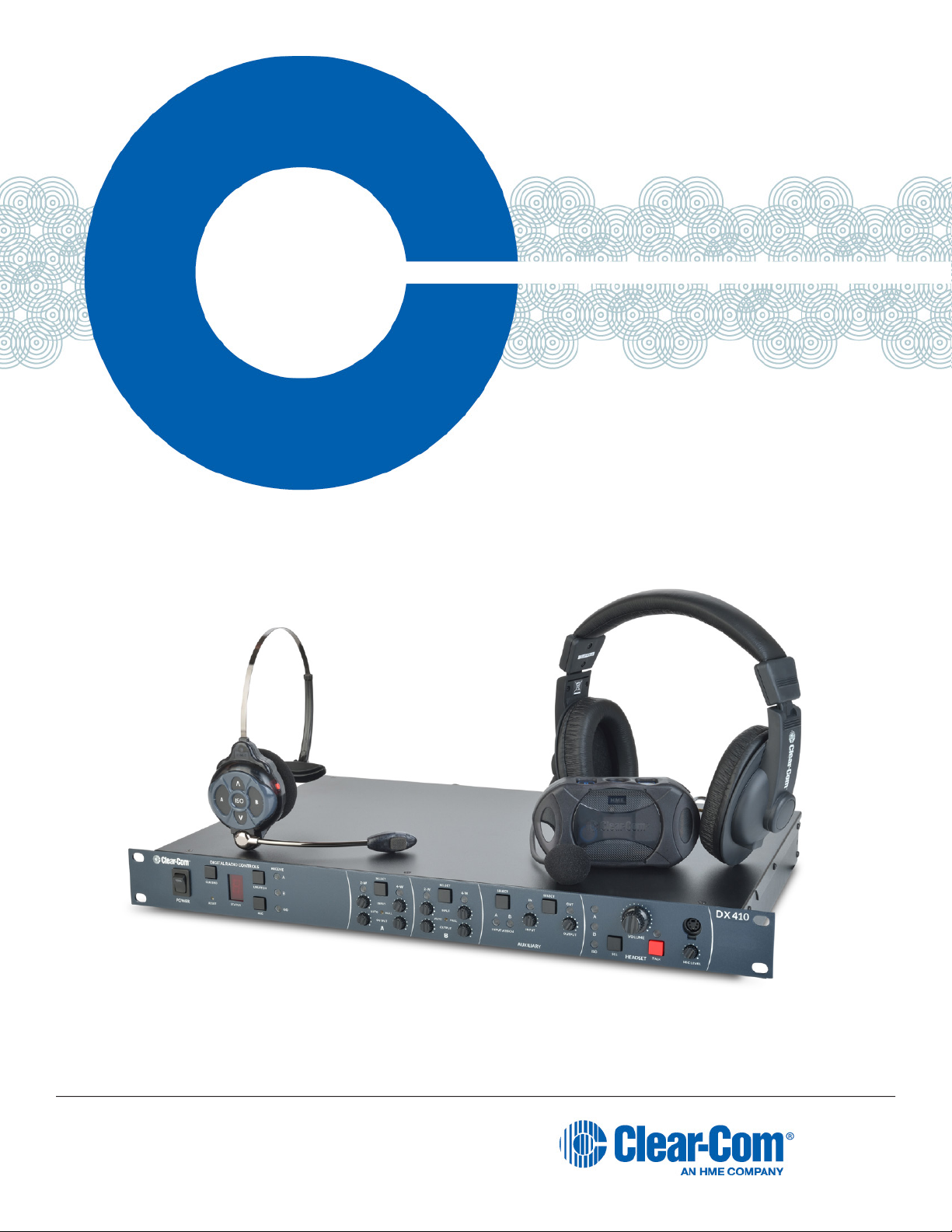
Clear-Com HME DX410
Dual-Channel Wireless Intercom
Part Number: 399G162 Rev C
Date: 5/22/17
Page 2

Copyright © 2017 Clear-Com, LLC, an HM Electronics, Inc. company. All rights reserved.
Clear-Com, the Clear-Com logo and Clear-Com Concert are trademarks or registered trademarks of
HM Electronics, Inc.
The product described in this document is distributed under licenses restricting its use, copying,
distribution, and decompilation/reverse engineering. No part of this document may be reproduced in
any form by any means without prior written authorization of Clear-Com, an HME Company.
Clear-Com Ofces are located in California, USA; Cambridge, UK; Montreal, Canada; and Beijing,
China. Addresses and contact information can be found on Clear-Com’s corporate website at www.
clearcom.com.
Clear-Com Contacts
Americas and Asia-Pacic Headquarters
California, United States
Tel: +1.510.337.6600
Email: CustomerServicesUS@clearcom.com
Europe, Middle East, and Africa Headquarters
Cambridge, United Kingdom
Tel: +44 1223 815000
Email: SalesSupportEMEA@clearcom.com
Canada Ofce
Quebec , Canada
Tel: +1 (450) 653-9669
China Ofce
Beijing Representative Ofce
Beijing, P.R.China
Tel: (008610)-8528-8748
2
Page 3

FCC NOTICE
This device complies with Part 15 of the FCC rules. Operation is subject to the following two conditions: (1) This device
may not cause harmful interference, and (2) This device must accept any interference received, including interference
that may cause undesired operation.
NOTE: This equipment has been tested and found to comply with the limits for a Class A digital device, pursuant to Part
15 of the FCC rules. These limits are designed to provide reasonable protection against harmful interference when the
equipment is operated in a commercial environment. This equipment generates, uses and can radiate radio frequency
energy and, if not installed and used in accordance with the instruction manual, may cause harmful interference to radio
communication. Operation of this equipment in a residential area is likely to cause harmful interference, in which case
the user will be required to correct the interference at his own expense.
Changes or modications not expressly approved by Clear-Com, LLC, an HM Electronics, Inc. company could void the
user’s authority to operate this equipment.
MANDATORY SAFETY INSTRUCTIONS
FOR INSTALLERS AND USERS
Use only manufacturer or dealer supplied antennas, power supplies, batteries and battery chargers. The Federal
Communications Commission has adopted a safety standard for human exposure to RF (Radio frequency) energy,
which is below the OSHA (Occupational Safety and Health Act) limits.
Base Station Antenna minimum safe distance: 7.9 inches (20 cm) at 100% duty cycle.
Base Station Antenna gain: This device has been designed to operate with an antenna having a maximum gain of up to
7dBi.
Antenna mounting: The antenna(s) used for the base transmitter must be installed to provide a separation distance of at
least 7.9 inches (20 cm) from all persons and must not be co-located or operating in conjunction with any other antenna
or transmitter.
Antenna substitution: Do not substitute any antenna for the one supplied by the manufacturer. You may be exposing
person or persons to excess radio frequency radiation. You may contact your dealer or the manufacturer for further
instructions.
WARNING: Maintain a separation distance from the base station transmit antenna to a person(s) of at least 7.9 inches
(20 cm) at 100% duty cycle.
WARNING: Excessive sound pressure level from earphones or headphones can cause hearing loss. You, as the
qualied end-user of this radio device must control the exposure conditions of bystanders to ensure the minimum
separation distance (above) is maintained between the antenna and nearby persons for satisfying exposure
compliance. The operation of this transmitter must satisfy the requirements of Occupational /Controlled Exposure
Environment, for work-related use. Transmit only when person(s) are at least the minimum distance from the properly
installed, externally mounted antenna.
Canada IC Notice to Users English/French in accordance with RSS GEN
This device complies with Industry Canada license-exempt RSS standard(s). Operation is subject to the following two
conditions: (1) this device may not cause interference, and (2) this device must accept any interference, including
interference that may cause undesired operation of the device.
Cet appareil est conforme avec Industrie Canada RSS standard exempts de licence (s). Son utilization est soumise à
Les deux conditions suivantes: (1) cet appareil ne peut pas provoquer d'interférences et (2) cet appareil doit accepter
Toute interférence, y compris les interférences qui peuvent causer un mauvais fonctionnement du dispositif.
3
Page 4

Hereby, Clear-Com, LLC, an HM Electronics, Inc, company, declares that the DX410 is in compliance with the essential
requirements and other relevant provisions of the RED (Radio Equipment Directive). In AFH mode, complies with
European Telecommunications Standards Institute (ETSI) harmonized European standard EN 300 328.
This product operates in the 2400 to 2483.5 MHz frequency range. The use of this frequency range is not yet harmonized
between all countries. Some countries may restrict the use of a portion of this band or impose other restriction relating to
power level or use. You should contact your Spectrum authority to determine possible restrictions.
Korea KCC EMC Class A Warning
A급기기(업무용방송통신기자재)
이 기기는 업무용 환경에서 사용할 목적으로
적합성 평가를 받은 기기로서 가정용 환경에서
사용하는 경우 전파 간섭의 우려가 있습니다.
English: Class A (Commercial broadcasting and communication equipment) Sellers and user should note that this
equipment is an electromagnetic device for business (Class A) and intended for operation in non-residential locations.
Korea KCC 2.4Ghz device warning
해당 무선설비는 전파혼신 가능성이 있으므로 인명안전과 관련된 서비스는 할 수 없음
English: This device cannot provide services related to human life safety.
WASTE ELECTRICAL AND ELECTRONIC EQUIPMENT (WEEE)
The European Union (EU) WEEE Directive (2012/19/EU) places an obligation on producers (manufacturers, distributors
and/or retailers) to take-back electronic products at the end of their useful life. The WEEE Directive covers most ClearCom products being sold into the EU as of August 13, 2005. Manufacturers, distributors and retailers are obliged to
nance the costs of recovery from municipal collection points, reuse, and recycling of specied percentages per the
WEEE requirements.
Instructions for Disposal of WEEE by Users in the European Union
The symbol shown below is on the product or on its packaging which indicates that this product was put on the market
after August 13, 2005 and must not be disposed of with other waste. Instead, it is the user’s responsibility to dispose of
the user’s waste equipment by handing it over to a designated collection point for the recycling of WEEE. The separate
collection and recycling of waste equipment at the time of disposal will help to conserve natural resources and ensure that
it is recycled in a manner that protects human health and the environment. For more information about where you can
drop off your waste equipment for recycling, please contact your local authority, your household waste disposal service or
the seller from whom you purchased the product.
Clear-Com, LLC, an HM Electronics, Inc. company, is not responsible for equipment malfunctions due to erroneous
translation of its publications from their original English version. Illustrations in this publication are approximate
representations of the actual equipment, and may not be exactly as the equipment appears.
4
Page 5

TABLE OF CONTENTS
System Overview ...................................................................6
System Components .......................................................................6
Base Station Front Panel....................................................................7
Base Station Rear Panel ....................................................................8
Belt Pack – BP410.........................................................................8
All-In-One Headset – WH410 ................................................................9
System Setup ......................................................................10
Battery Charging ..........................................................................10
Connect AC Power Supply ..................................................................10
Charging the Batteries......................................................................11
Basic Base Station Setup ...................................................................12
COMMUNICATOR® Setup and Registration .....................................................13
Interfacing with 2-Wire or 4-Wire Intercoms .....................................................17
Interfacing with Auxiliary Audio Equipment ......................................................18
ISO Relay ...............................................................................19
System Operation...................................................................20
Base Station Operation .....................................................................20
COMMUNICATOR® Operation .........................................................21
EU BASE STATION Adaptive Frequency Hopping ........................................23
Troubleshooting ....................................................................26
Technical Data .....................................................................27
BS410 Base Station Specications ............................................................27
BP410 Belt Pack Specications ..............................................................28
WH410 All-In-One Headset Specications ......................................................29
Appendix A: COMMUNICATOR® Indicator Light Functions .................................30
BP410 Belt Pack Indicator Lights .............................................................30
WH410 All-In-One Headset Indicator Lights .....................................................30
Appendix B: Multiple Base Station Daisy-Chaining .......................................31
Appendix C: Jumper Settings .........................................................32
ISO Broadcast Restrict .....................................................................32
2-Wire Channel Termination .................................................................32
Appendix D: Interference Avoidance Through Spectrum Friendly ...........................33
Spectrum Friendly .........................................................................34
Avoiding Wi-Fi Interference ..................................................................34
DX SERIES LED AID.................................................................35
Syncing Primary to Secondary Bases Feature ...................................................35
Spectrum Friendly Feature ..................................................................36
Appendix E: Audio Routing Diagram ...................................................37
General Battery Safety Instructions for Battery Model BAT41, BAT50, BAT60 .................38
French ..................................................................................39
Spanish .................................................................................40
Korean ..................................................................................41
5
Page 6
SYSTEM OVERVIEW
The Clear-Com® HME DX410 is a 2-channel Digital Wireless Intercom System that supports up to 15
COMMUNICATOR®s per base station, either Belt Packs or All-In-One Headsets, or a combination of the two.
Using the DX410 in the 2-channel mode, any three of the 15 Communicators can operate in full duplex mode. In the
single-channel mode, any four Communicators can operate in full duplex mode. This number can be increased by adding
up to three additional base stations. The DX410 supports both Clear-Com and RTS cabled 2-wire intercom systems, and
also has 4-wire and auxiliary audio connections.
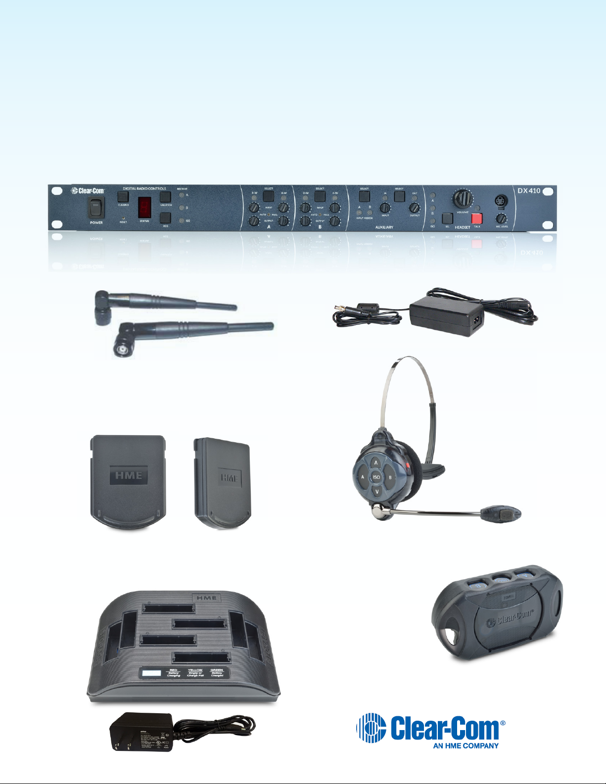
System Components
BS410 Base Station
Antennas 110/240 Switching Power Supply
AC50 Batteries
AC50 Battery Charger and Power Supply Adapter
WH410
All-In-One Headset
BP410 Belt Pack
6
Page 7
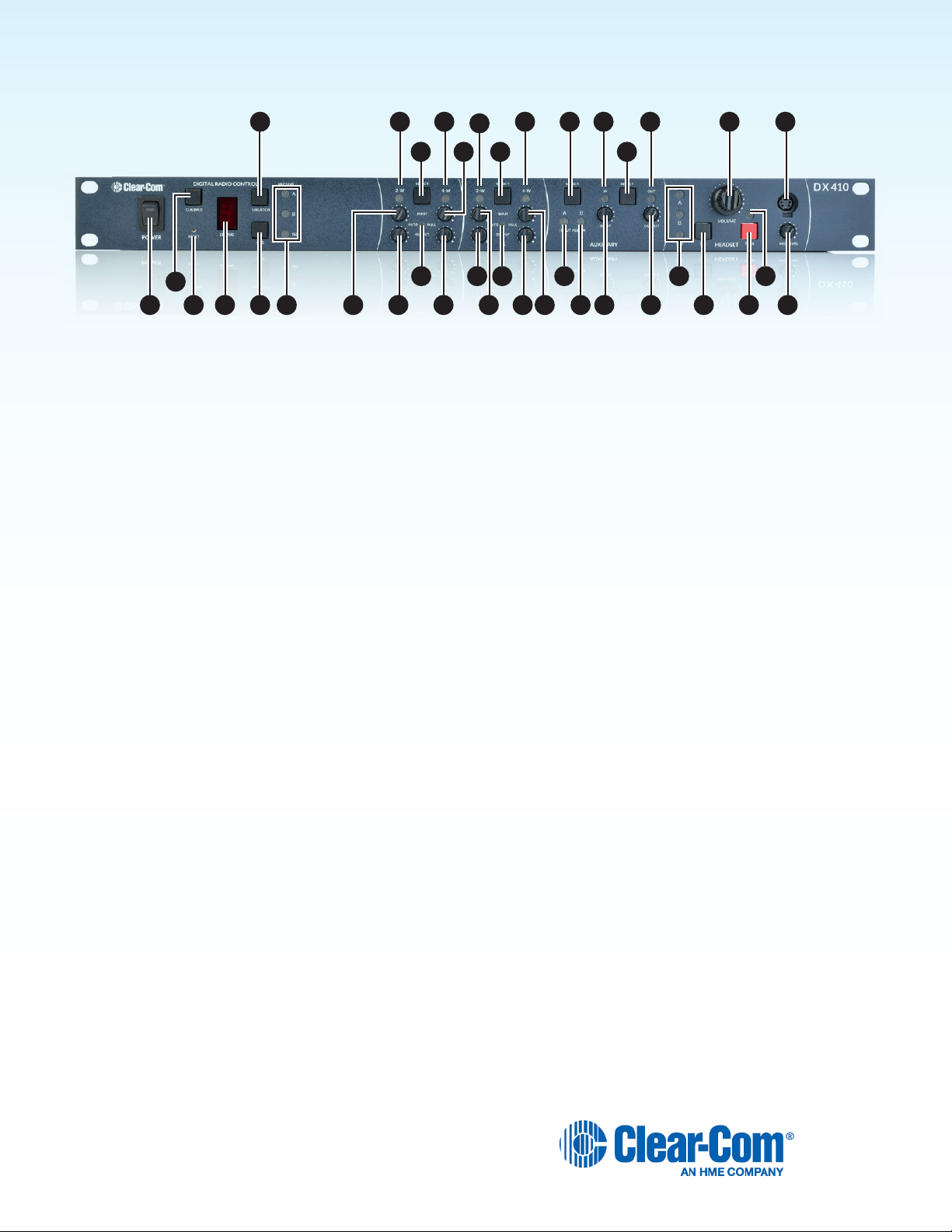
Base Station Front Panel
6
2
1 3 4 5 7 8 9
Digital Radio Controls
1. POWER switch
2. CLR/BND button
3. RESET button (recessed)
4. STATUS display
5. REG (registration) button
6. UNLATCH button
7. RECEIVE indicator lights
A Controls
8. (A) 2-W output level adjust
101213
14
11 18 20
15 17 22 213626 28 31
16
19
23 24 27
20. (B) AUTO NULL button (recessed)
21. (B) 4-W input level adjust
22. (B) 4-W output level adjust
23. (B) 4-W indicator light
Auxiliary Controls
24. AUX INPUT SELECT button
25. AUX A INPUT ASSIGN indicator
26. AUX B INPUT ASSIGN indicator
27. AUX IN indicator light
25
30 34 37
29
32
33 35 38
9. (A) 2-W input level adjust
10. (A) 2-W indicator light
11. (A) AUTO NULL button (recessed)
12. (A) 2-W/4-W SELECT button
13. (A) 4-W indicator light
14. (A) 4-W input level adjust
15. (A) 4-W output level adjust
B Controls
16. (B) 2-W indicator light
17. (B) 2-W input level adjust
18. (B) 2-W output level adjust
19. (B) 2-W/4-W SELECT button
28. AUX INPUT level adjust
29. AUX OUTPUT SELECT button
30. AUX OUT indicator light
31. AUX OUTPUT level adjust
Headset Controls
32. HEADSET A, B & ISO indicator lights
33. HEADSET A, B & ISO SELECT button
34. HEADSET VOLUME knob
35. HEADSET TALK On/Off button
36. HEADSET TALK indicator light
37. HEADSET MIC LEVEL adjust
38. HEADSET cable connector
7
Page 8
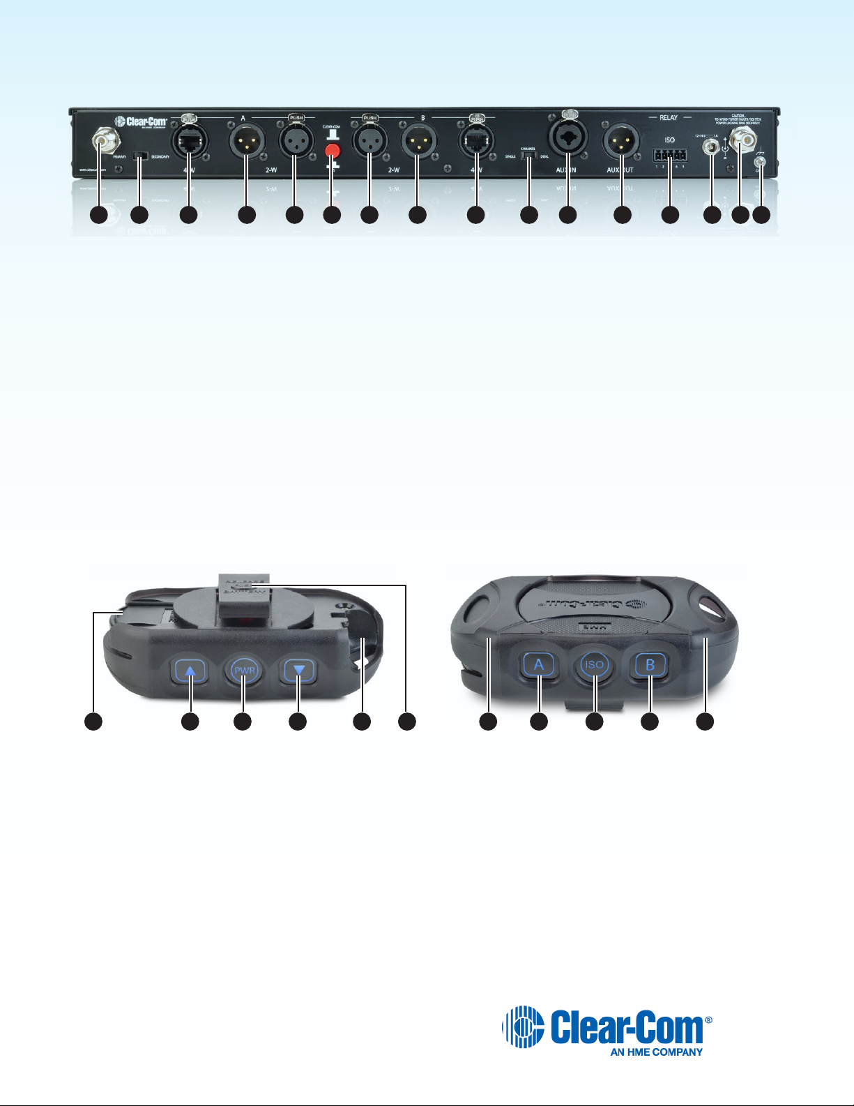
Base Station Rear Panel
1 2 3 4 85 6 7 9 10 161311 12 1514
1. ANT (R-TNC)
2. PRIMARY/SECONDARY Select Switch
3. (A) 4-W RJ-45 Connector
4. (A) 2-W XLR-3M Connector
5. (A) 2-W XLR-3F Connector
6. CLEAR-COM/RTS Select Switch
7. (B) 2-W XLR-3F Connector
8. (B) 2-W XLR-3M Connector
Belt Pack – BP410
9. (B) 4-W RJ-45 Connector
10. SINGLE/DUAL Channel Select Switch
11. AUX IN Connector
12. AUX OUT Connector
13. Relay Connector
14. DC Power Connector
15. ANT (R-TNC)
16. Chassis Grounding Screw
1. Battery
2. Volume-up button
3. PWR (Power) button
4. Volume-down button
5. Headset cable connector
7 78 9 1021 63 4 5
6. Battery-release latch
7. Power/mode lights
8. Channel A (Intercom 1) button
9. ISO (Isolate) button
10. Channel B (Intercom 2) button
8
Page 9
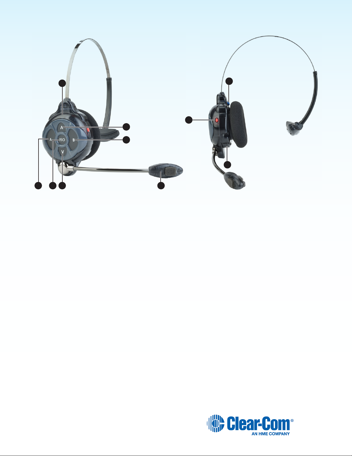
All-In-One Headset – WH410
6
1 2
4 7
1. Channel A (Intercom 1) button
2. ISO (Isolate) button
3. Volume-up button
4. Volume-down button
10
8
3
5
9
6. Power/mode light
7. Microphone
8. Power button
9. Battery
5. Channel B (Intercom 2) button
10. Battery-release latch
9
Page 10
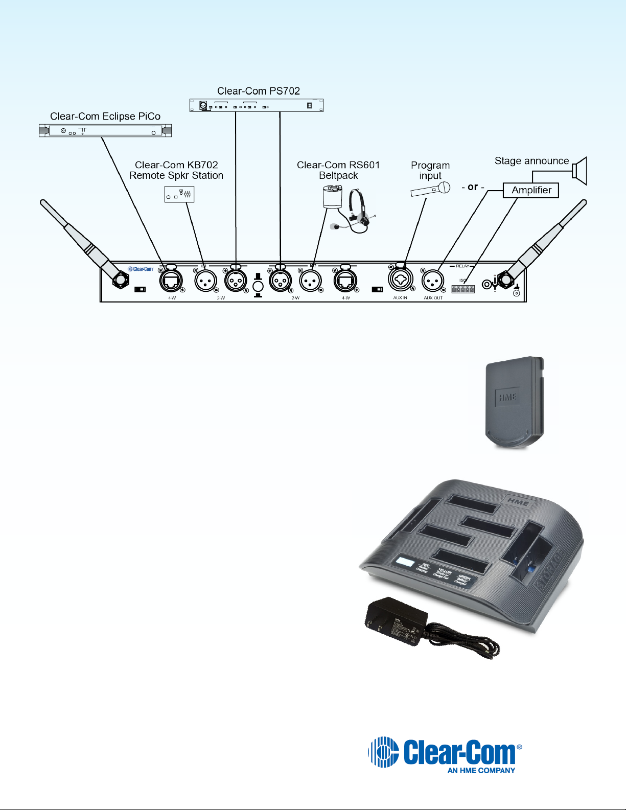
SYSTEM SETUP
Displayed below is an example of a typical Clear-Com set up and conguration with the DX410.
Battery Charging
Before installing the system, connect the AC power supply to the battery charger and plug it
into an electrical outlet. Charge all the batteries while the other equipment is being installed.
Charging time is about 2.5 hours.
Connect AC Power Supply
To connect the AC power supply to the battery charger:
1. Connect the AC power supply cable connector to the
power connection on the battery charger.
2. Connect the AC power cord to an electrical outlet.
The red lights on the charger will briey display, and then the yellow
lights will appear and remain on.
10
Page 11

Batteries in
Charging ports
Batteries in
Storage ports
Charging the Batteries
Up to four batteries can be charged in the battery charger at one time. The battery status lights next to each charging port
indicate the battery status. Up to four fully charged batteries can be stored in the battery Storage ports. Insert a battery in
each of four Charging ports until it clicks in place.
h A yellow light next to a Charging port indicates that the port is EMPTY.
h A red light next indicates that the battery port is CHARGING.
h A green light indicates that the battery is READY.
h A steady yellow light indicates that the CHARGE FAILED. If a charge fails, refer to the instructions on the side
of battery charger.
h A ashing yellow light next indicates CHARGE PENDING, which means the inserted battery is too hot. Adjust
the room temperature or move the charger to a cooler area.
h Store fully charged batteries in storage ports.
NOTE: Batteries should not be left in charge ports after being fully charged. A battery left in a charging port for
more than three weeks may display the yellow indicator light, but it does not indicate a faulty battery.
11
Page 12
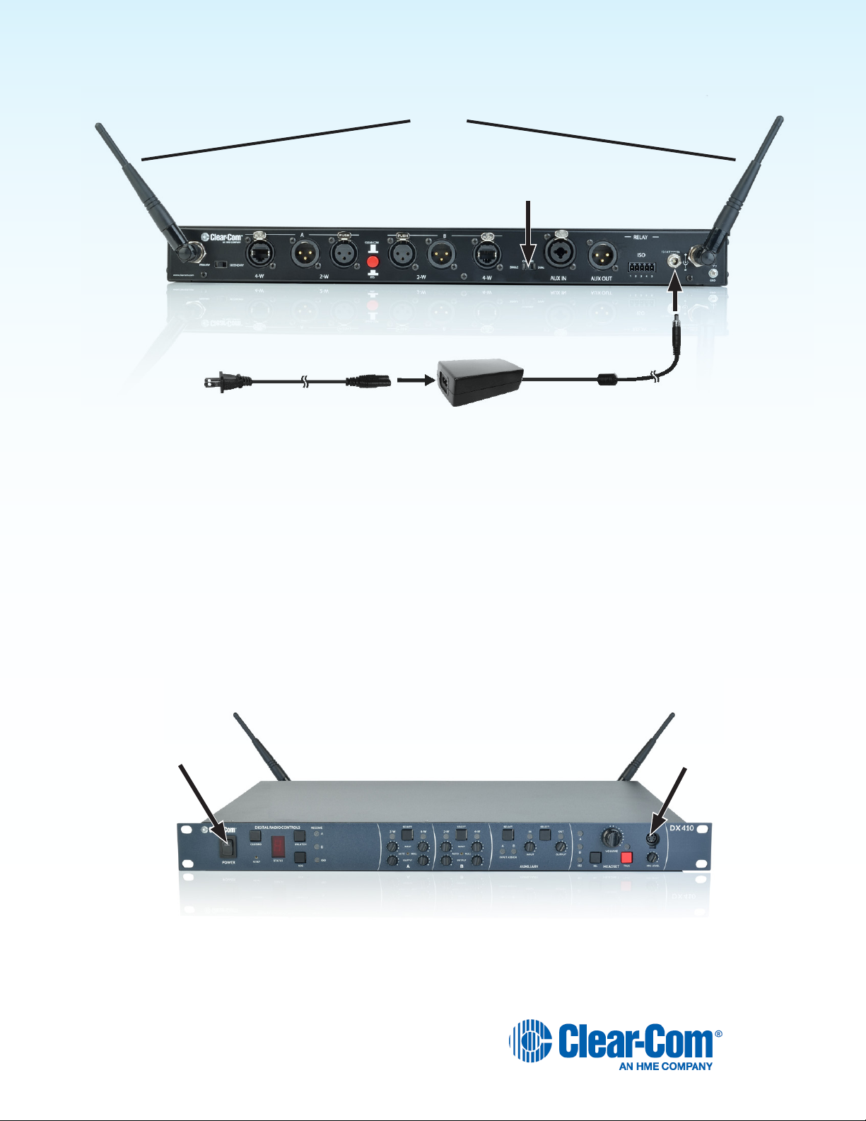
Basic Base Station Setup
This section describes setup and equipment connections for an individual base station.
90°
SINGLE/DUAL Channel select switch
Base station rear panel
AC power cord
1. Connect the two enclosed antennas to the antenna connectors on the rear panel of the base station, and turn
the sleeves clockwise on the antenna connectors to tighten them securely in place. Position the antennas at
90° angles from each other.
2. Plug the connector at the end of the AC power supply cord into the +12-14VDC power connector on the rear
panel of the base station (as shown above). Turn the locking nut on the cable connector clockwise to secure it
to the base station. Plug the female connector at one end of the AC power cord into the power supply. Plug the
other end of the AC power cord into an electrical outlet.
3. Set the SINGLE/DUAL Channel select switch for the base station to operate in Single or Dual channel mode.
h In Single Channel mode, all wireless users will be able to hear each other. Up to four users can talk
simultaneously.
h In dual channel mode, there are two separate audio channels enabling two groups of users to
independently communicate with each other. Up to three users can talk simultaneously.
NOTE: Any time the mode is changed, the unit must be reset using the RESET button or by power
cycling for the change to take effect.
AC power supply
Headset connectorPower switch
1. If a local headset will be used, plug it into the HEADSET connector on the front panel of the base station.
NOTE: The connector is keyed, so the headset cable plug cannot be inserted in the wrong direction.
2. Press the POWER switch on the front panel to turn on the base station. A red light on the switch should go on.
12
Page 13
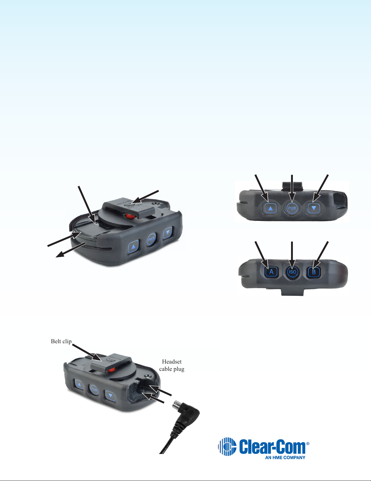
COMMUNICATOR® Setup and Registration
Belt clip
Headset
cable plug
The rst time you operate the DX410 system, you must register each Communicator (Belt Pack and/or All-In-One
Headset) for use with a specic base station. The base station will then recognize all registered Communicators when
their power is on and will differentiate between them and other electronic equipment operating on the same frequencies.
If a Communicator is added or replaced later, the new one must be registered and the old one remains in memory. A
maximum of 15 Communicators can be registered to a single base station at one time.
Set Up COMMUNICATOR®s
Before registering them, set up all Communicators as follows:
The Belt Pack
h Insert a fully charged battery in each Belt Pack with the metal contacts inserted rst. Slide it in until it snaps.
NOTE: The battery will not slide in if inserted incorrectly. Excessive force should not be necessary.
h Plug the belt pack’s headset cable connector into each Belt Pack.
Battery
RELEASE BATTERY
button
Removing the battery
When a Communicator battery becomes weak, a headset voice
prompt will say “Change battery.”
Press the RELEASE BATTERY button on the belt clip of the
pouch, and use your thumb to slide the battery from the belt-pac.
Volume-Up
button
Channel
A
Power
button
ISO
Volume-Down
button
Channel
B
13
Page 14
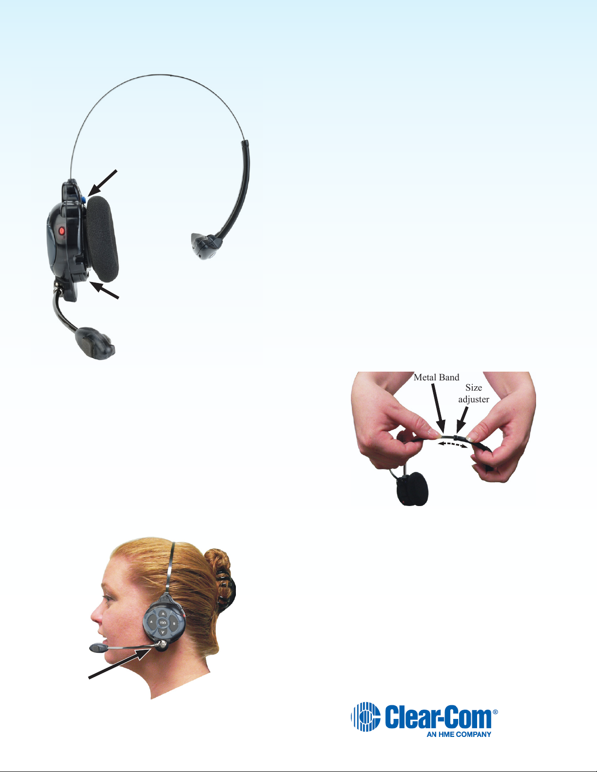
All-In-One Headsets
Metal Band
Size
adjuster
Changing Batteries
When a battery weakens, a prompt in the headset will say “Change
battery”. Remove the battery from the headset by pressing the blue
battery-release latch.
Battery-release latch
(blue button)
Battery
Insert a fully charged battery in each Headset, with the battery’s
metal contacts inserted rst. Press it in until it snaps.
NOTE: The battery will not slide in if inserted incorrectly. Excessive
force should not be necessary.
Adjust the Headset to Your Head Size
You can adjust the head size of the Headset by sliding
the metal headband in or out of its plastic size adjuster.
Microphone
adjustment
Place the Headset on your head
1. The headset can be worn with the microphone and
controls on either side of your head.
2. Hold the microphone boom at its base, and adjust
it so that the microphone is near the side of your
mouth.
14
Page 15

Register COMMUNICATOR
The Communicator must be within 6 feet (1.83 meters) of the base station to enable registration.
1. Be certain all headsets to be registered are turned OFF, and the base station power is ON.
2. Place the headset on your head.
3. Press the REG button on the front panel of the base station. The STATUS display will show a
small “o” for open.
NOTE: If you wait too long before going on to the next step, the base station will exit
registration mode, requiring that you press the REG button again.
4. Press and hold the ISO button on the Communicator while you press and release the
Power button (PWR). After power up, release the ISO button. The Communicator will
enter Registration mode.
On Belt Packs, the two power lights at the corners near the A and B buttons will
begin blinking red, and then they will blink green two or three times then turn off.
Note: There may be a short delay.
On All-In-One Headsets, the power/mode lights located at the end of the
microphone boom and on the side of the unit near the A button will blink.
Note: There may be a short delay.
®
s
If registration is successfully completed:
h A voice prompt in the headset will say “Battery level, begin registration…”.
h After a delay of about 15 seconds, the STATUS display will show the ID number assigned to the
Communicator for about 10 seconds.
NOTE: ID numbers are assigned sequentially 0 through 9, then A, b, C, d and E.
h The power light on the Communicator will display steady green.
If registration failed:
h A voice message in the headset will say “Battery level, begin registration…” Both lights
on the Belt Pack will be blinking red, and there may be a delay of up to 90 seconds
before you hear “Registration failed.”
h Press the RESET button at the lower-left corner of the base station with a pen or similar
pointed object. When the STATUS display becomes blank, press the REG button
and register the Communicator again. If registration fails again, call your dealer for
assistance.
If you try to register more than 15 Communicators:
h An “F” will appear on the STATUS display on the base station and you will hear “Registration failed”
in the headset.
h Clear all current registrations by pressing the CLR/BND button and the RESET button at the same
time. To press the RESET button, insert a pen or similar pointed object into the RESET hole at the
lower-left corner of the base station front panel. Continue holding the CLR/BND button after you
release the RESET button, until the clear code “c” (lower case) appears on the STATUS display.
h Register all active Communicators, one at a time. Previously registered Communicators must be
re-registered.
15
Page 16

COMMUNICATOR
®
Settings
If you want to set up a Communicator with any of the special settings shown below, press and hold the specied button
combinations during or after power up. These settings will remain in memory when the Communicators are turned off and
on again.
For Setting Press & Hold while you Press and Release the Power button
ISO restrict On A button
ISO restrict Off A and ISO buttons
Handsfree On selected button(s) A and/or B and/or ISO and ▲ volume up button
Handsfree Off selected buttons(s) A and/or B and/or ISO and ▼ volume down button
Listen-Only mode On ▼ volume down button
Listen-Only Off ▲ volume up button
WH410 only *
All-In-One Headset “lights-off” mode
* NOTE: All-In-One Headsets can be set up with its indicator lights off, to avoid distraction if users are in an area visible to audience.
This setting is not saved when you power off.
For Setting With the power already on...
Increase mic gain (15 steps) Press B while you repeatedly press the ▲ volume up button
Decrease mic gain (15 steps) Press B while you repeatedly press the ▼ volume down button
BP410 only *
Increase sidetone level (5 steps)
BP410 only *
Decrease sidetone level (5 steps)
* NOTE: There is no sidetone adjustment function for All-In-One Headsets.
B button
Press A while you repeatedly press the ▲ volume up button
Press A while you repeatedly press the ▼ volume down button
If you are not connecting a wired intercom, go on to System Operation (pg. 20).
16
Page 17

Interfacing with 2-Wire or 4-Wire Intercoms
1 2 3 4
Base station rear panel
2-Wire Intercom Interface
The following 2-wire setup is for Channel 1 (A). If applicable, repeat for Channel 2 (B).
h If using a 2-wire intercom with the DX410, plug it into the base station 2-W connector at (2) or (3),
depending on whether a male or female connection is required.
h Depending on whether you are using a Clear-Com® or RTS® compatible 2-wire intercom system, position the
4
CLEAR-COM / RTS button (
h Press the A SELECT button on the front panel of the base station. The 2-W light next to the button should
turn green.
NOTE: If no power is detected at the 2-W connector, the 2-W light will illuminate red and no audio will be
passed through. Plugging a connection into a Clear-Com or RTS power supply will turn the light green and
operation will begin.
) as follows: In position = RTS Mode Out position = Clear-Com Mode
h Make certain there are no open microphones on the wired intercom. If users are wearing headsets, please
notify them of the impending audio sweep prior to auto nulling.
h Press and hold the AUTO NULL button for two seconds. To press the AUTO NULL button, insert a pen or
similar pointed object into the AUTO NULL hole on the front panel of the base station. An audio sweep will be
heard for 25 seconds on the wired Belt Packs. (The 2-W light next to the button should turn amber, then green.)
h Adjust the 2-W intercom receive and send levels with the A 2-W INPUT control and OUTPUT control.
NOTE: If you are not connecting other equipment, go on to System Operation (pg. 20).
4-Wire Intercom Interface
The following 4-wire setup is for Channel 1 (A). Repeat for Channel 2 (B) if applicable.
h If using a 4-wire intercom with the DX410, plug it into the base station A
4-W connector (1).
h Press the respective SELECT button until the A 4-W light next to the
button goes on.
h Adjust the 4-wire intercom receive and send levels with the A 4-W INPUT
and OUTPUT controls.
RJ45 Connector Pins Designation
Pins 1, 2, 7 and 8 N/C (reserved)
Pin 3 Intercom Out +
Pin 4 Intercom In +
Pin 5 Intercom In –
Pin 6 Intercom Out –
17
Page 18

A and B Intercom Controls and Indicator Lights
6 8751 3 42
Base station
front panel
The A portion of this area of the panel is for Intercom Channel A, and the B portion is for Intercom Channel 2. Their
operation is identical.
h The SELECT button (4) is used to select 2-Wire (3) or 4-Wire (6) or both. The 2-W indicator light will
display red (muted) if wired intercom power is not detected at the 2-W connector on the rear panel of the base
station. The 2-W indicator light will display green if 2-W equipment which supplies power is plugged into the
2-W connector on the rear panel of the base station, or if the respective bypass jumper inside the unit has
been set.
h The INPUT controls (
headset, coming in from 2-W and 4-W equipment connected to the base station.
h The OUTPUT controls (
local headset going out to 2-W and 4-W equipment connected to the base station.
h The AUTO NULL button (5) is used to eliminate echo caused by mismatched line characteristics of an
external 2-W system.
CAUTION: Before pressing the AUTO NULL button, be sure there are no open microphones on the wired
system. Use a pen or similar pointed object to depress and hold the AUTO NULL button for 2 seconds.
NOTE: If you are not connecting other equipment, go on to System Operation (pg. 20).
2
and 7) are used to adjust the audio levels going to COMMUNICATOR®s or a local
1
and 8) are used to adjust the audio levels coming in from Communicators or a
Interfacing with Auxiliary Audio Equipment
ISO Audio can be routed to the AUX OUT connector for page or stage announce.
h If using auxiliary audio equipment, such as another intercom or an audio player, connect its output cable
connector (male) to the AUX IN connector (9), and/or its input cable connector (female) to the AUX OUT
connector (10).
9 10
Base station rear panel
The cable connectors must be 3-pin XLR type for balanced +20dBu Pin 1 = Ground maximum audio input/output, with
Pin 2 = Audio + the following pin connections:
1
1
Pin 1 = Ground
Pin 2 = Audio +
Pin 3 = Audio –
2 2
3
3
18
Page 19

The AUXILIARY SELECT button (2) is used to select A or B or both as the destination for AUX IN audio. The A and/
or B INPUT ASSIGN lights (1) come on green to indicate the selection as the destination for AUX IN audio. If neither is
selected, AUX IN audio will not be routed to the COMMUNICATOR®s. The AUX IN light must be lit for the INPUT ASSIGN
SELECT function to work.
1 732 54 6
h If only AUX IN is used, press the AUX IN/OUT SELECT
button (5) until the IN light (4) turns on. Listen to the
audio input in your headset as you adjust the INPUT
control (3) to the desired level.
h If only AUX OUT is used, press the AUX IN/OUT
SELECT button (5) until the OUT light (6) comes on.
Check the audio level on the auxiliary equipment, and
adjust the OUTPUT control (7) to the desired level.
h If the auxiliary equipment requires two-way
communication, have someone listening at the auxiliary
unit. Press the AUX IN/OUT SELECT button (5) until
both the IN and OUT lights (4 and 7) turn on. While
speaking into the headset microphone, adjust the OUT control (7) above the light to the desired listening
level at the auxiliary unit. Listen to the audio input in your headset as you adjust the INPUT control (3) below
the light to the desired level.
Base station rear panel
Auxiliary Controls and Indicator Lights:
h The SELECT button on the right (5) is used to select AUX IN (audio from auxiliary equipment
connected to the base station), AUX OUT (audio to the auxiliary equipment from the ISO channel of the
COMMUNICATOR®s and local headset) or both.
h The IN and OUT lights illuminate green to indicate the selection.
h The INPUT and OUTPUT controls adjust auxiliary inbound and outbound audio levels.
h The SELECT button on the left (2) is used to select A or B or both as the destination for AUX IN audio. The
A and/or B destination for AUX IN audio. INPUT ASSIGN lights come on green to indicate the selection as the
destination for AUX IN audio.
NOTE: If you are not connecting other equipment, go on to System Operation (next page).
ISO Relay
During ISO communication, a relay closure is provided. This can be used for tasks such as keying a long range radio or
triggering an alert light. It can be activated from a Communicator or a local headset.
1 = Normally closed
2 = Common
3 = Normally Open
4 = not used
5 = Ground
Base station rear panel
19
Page 20

SYSTEM OPERATION
This chapter describes how to operate the Base Station and COMMUNICATOR® (Belt Pack or All-In-One Headset).
Base Station Operation
COMMUNICATOR
Registration
®
Audio Channel and
Auto-Null Controls
Local Headset
Connector & Controls
Power Switch
AUX IN Assign and
AUX In/Out Controls
System and Registration Controls and Indicator Lights
h The CLR/BND button, RESET button, STATUS indicator and REG button are used when registering
Communicators. Refer to COMMUNICATOR® Setup and Registration (pg. 13).
h The UNLATCH button is used by the base station operator to turn off microphones on all Communicator
transmitters.
h The RECEIVE A, B (Intercoms) and ISO (Isolate) lights indicate whether reception from a Communicator is on
A, B or ISO.
Local Headset Connector, Controls and Indicator Lights
h The SEL button (Select) is used to select
communication from the local headset to A, B, A &
B, or ISO.
h The A, B, A & B, or ISO indicator light will be lit for
the selection you made.
h A and B communication will be heard by wireless
users on the respective channel, as well as users
wired into 2-W and 4-W connections.
h ISO is heard in both wireless channels, and AUX OUT if activated.
NOTE: When the ISO button is pressed, ISO RELAY is activated.
h The TALK button (red) is used for communication from the local headset to the selected channel. For open
communication, press and release the TALK button quickly to “latch on.” To “latch off,” press and release the
button again quickly.
For momentary communication, press and hold the TALK button for more than one second. In this mode, the
selected channel will remain open only as long as you are pressing the TALK button. The TALK light indicates
the TALK mode is active via the local headset.
h Use the VOLUME control to adjust the output to the local headset ear piece.
h Use the MIC LEVEL control to adjust the audio level from the local headset microphone.
20
Page 21

COMMUNICATOR® OPERATION
Belt Pack control buttons have a snap action. They will activate when pressed rmly. Use your ngertips (not your
ngernails) to press the Belt Pack buttons. All-In-One Headset buttons are touch sensitive.
Power On/Off
h Power On – Press and release the Power button (PWR). A voice prompt in the ear piece will say “Battery
Level”, and the red power lights near the corners of the A and B buttons will turn on. After a short time, one
light will go off and the other will change to green, indicating the Belt Pack is ready for use. The STATUS
indicator on the base station will momentarily indicate the ID of the Belt Pack. The green power light will be on
steady whenever the Belt Pack is ready, but not transmitting.
NOTE: While the Belt Pack is transmitting, the green power light will be ashing.
h Power Off – Press and hold the PWR button for approximately two seconds. A voice message in the ear
piece will say “power off”, and the green power light will turn off.
ISO (Isolate) and A, B (Intercom)
Use the ISO button to talk to other wireless Communicator users and the base station operator. Pressing ISO on the Belt
Pack will also send audio to AUX OUT if the AUXILIARY OUT light on the front of the base station is on. Use the A and B
buttons to communicate via the wired intercom channels and the base station operator. When the ISO button is pressed,
ISO RELAY is activated.
Operating Modes
h Push-To-Talk ONLY Mode Operation – In PTT operation, audio is transmitted only while you are pressing
and holding the A, B or ISO button. When you release the button, transmission stops.
h Hands-free Mode Operation – Quickly press and release the A, B or ISO button to “latch” the transmitter on.
Talk and listen, as in a normal telephone conversation. Quickly press and release the same button again to
“unlatch,” and end the conversation. The base station operator can unlatch all Communicators by pressing the
UNLATCH button on the base station.
NOTE: In the hands-free mode, if you are latched in A, B or ISO, quickly pressing/releasing either of the other
buttons will latch on that button.
Also in the hands-free mode, if you are latched in A or B and then press and hold the ISO button, it will function as PTT.
When you release the ISO button, the Communicator will revert to the latched A or B.
Refer to Communicator indicator light functions, Appendix A (pg. 30).
Volume Up/Down
h Volume Up Adjustment – Each time you press and release the volume-up ▲ button, a beep will be heard in
the ear piece as the volume increases one step. If you press and hold the ▲ button, repeating beeps will be
heard as the volume steps up to maximum. When maximum volume is reached, “maximum” will be heard in
the ear piece, and it will be repeated until you release the ▲ button.
h Volume Down Adjustment – Each time you press and release the volume-down ▼ button, a beep will be
heard in the ear piece as the volume decreases one step. If you press and hold the ▼ button, repeating
beeps will be heard as the volume steps down to minimum. When minimum volume is reached, rapidly
repeating beeps will be heard.
21
Page 22

Adjusting Microphone Gain
Some users talk louder/softer than others. To allow for this, microphone gain adjustment is available.
h To increase microphone gain – While holding down the B button, press the volume-up ▲ button as many
times as necessary to reach the desired level. The microphone gain increase can be monitored through side
tone, or preferably by someone else using a Communicator or at the base station.
h To decrease microphone gain – While holding down the B button, press the volume-down ▼ button as
many times as necessary to reach the desired level. The microphone gain decrease can be monitored through
side tone, or preferably by someone else using a Communicator or at the base station.
NOTE: The mic gain setting will be indicated, in number format, by a voice prompt (typically, HS14 = 5, HS15
= 3, HS16 = 3). You will hear “Maximum” if you attempt to go higher than maximum mic gain. You will hear
repeating beeps if you attempt to go lower than minimum mic gain. Microphone gain will be saved in memory
and does not require readjustment each time the power is turned on. The Default setting is 3.
Adjusting BP410 Belt Pack Side Tone
h To increase side tone – Press the volume-up ▲ button while holding down the A button in the normal
operating mode.
h To decrease side tone – Press the volume-down ▼ button while holding down the A button in the normal
operating mode.
NOTE: The side tone setting will be indicated in numbers by a voice prompt. Default setting is “Max”.
Using WH410 All-In-One Headset Lights-Off Mode
The Lights-Off mode can be used to avoid audience distraction from the lights on the All-In-One Headsets.
h To operate in the Lights-Off mode, with the WH410 power off, press and hold the B button while you press the
POWER button, and then release both buttons.
h To get out of the Lights-Off mode, power the WH410 off and back on again without pressing the B button.
NOTE: There is no side tone adjustment number for the All-In-One Headset.
Changing COMMUNICATOR® Batteries
When a Communicator battery becomes weak, a prompt in the ear piece will say “Change battery”.
RELEASE BATTERY
Battery
button
Battery-release latch
(blue button)
Battery
Press the RELEASE BATTERY button on the belt clip of
the pouch, and use your thumb to slide the battery from the
belt-pac.
NOTE: You do not need to remove the pouch to remove or
insert the battery.
Remove the headset battery by pressing the blue
battery-release latch, and use your thumb to slide
the battery out.
22
Page 23

EU BASE STATION ADAPTIVE FREQUENCY HOPPING
Background
The Clear-Com DX wireless intercom systems utilize a Frequency Hopping Spread Spectrum (FHSS) radio in order to
provide robust communications.
This system operates in the unlicensed 2.4 GHz band. With the proliferation of other devices over the past few years in
the same 2.4 GHz band, instances where these devices and systems can interfere with each other has greatly increased.
To further complicate matters, the European Union has introduced new radio standards for equipment operating
in this band in an attempt to reduce interference between equipment from different manufacturers. This European
Telecommunications Standards Institute (ETSI) harmonized European standard is known as EN 300 328.
CLEAR-COM Adaptive Frequency Hopping
In order to reduce interference with other equipment and comply with these new regulations, Clear-Com has implemented
an Adaptive Frequency Hopping (AFH) mode for the new DX EU base stations. The key idea behind AFH is using only
the good frequencies, or channels, unoccupied by other equipment. The system scans for other signals and avoids these
signals during operation. Since the radio environment is constantly changing, there is a continuous process of scanning
for used frequencies and updating the list of good channels.
The Clear-Com system utilizes 46 discrete frequencies, or channels, within the 2.4 GHz spectrum in order to
communicate voice and data. The process of deciding which channels should be used is a 3-stage process. The process
includes scanning for occupied channels, the broadcast of a channel exclusion list and the use of the exclusion list. The
process is completed in three steps coexisting in time.
Below is the process is shown in Time. First, the system performs a channel scan to determine occupied channels. This
list is then broadcast to the communicator. The communicators and base station will use this list during period three.
The process is continuous, and as is illustrated below, the list could be constantly changing. Depending on the radio
environment, a maximum of 46 channels, and a minimum of 15 channels may be used by the system at any time.
Time ⇒
Ch. 1 Ch. 2 Ch. 3 Ch. 4 Ch. 5 Ch. 6 Ch. 7 Ch. 8
Scan Broadcast Use
Scan Broadcast Use
Scan Broadcast Use
Scan Broadcast Use
Scan Broadcast Use
Scan Broadcast Use
For instructions describing the process of setting the base to AFH or another scanning mode, see Appendix D:
Interference Avoidance Through Spectrum Friendly, pg. 33.
Available settings include:
High (H) - Scans the Higher frequencies.
Low (L) - Scans the Lower frequencies.
All (A) - All frequencies are scanned.
AFH (E) - (European Mode) Advanced Frequency Hopping searches for the best frequency.
23
Page 24

Operation in Severe Environments
During normal operation, the fact that the system is constantly changing the channel list in use is transparent to the
user. It is possible, however, that in an environment with severe interference that the system may experience a slight
degradation. In the AFH mode, the Clear-Com system will use a minimum of 15 channels. If the environment is very
crowded and less than 15 channels are truly available, there could be increased radio ‘packet loss’ due to the high
interference. The following symptoms may be observed with AFH systems in a highly congested radio environment:
h This may result in system ‘busy’ indications. Channel lists are updated every few seconds, and in a severe
environment it is possible that these lists get missed by the communicator.
h Slight degradation in audio delity between the headsets and base station. This would be due to the same
symptom as the ‘busy’ indications. The HD audio processing is tolerant to this condition, which is why the
degradation may only be slight.
h Longer times to register. Registration may take longer, since the headset has to acquire the channel list from
the base station. If the base station has excluded a lot of channels, this takes longer as the communicator
does not have the exclusion list and looks for the base on channels it is not using.
h Initial sync time increase. For the same reason registration may take longer, the initial headset sync on power
up may take longer.
Required AFH Equipment
In order to utilize AFH, the base station must be set to European mode. The headsets and belt packs must also be AFH
capable. AFH capable headsets and belt packs will have the letters ‘AFH’ labeled on the belt pack and headsets. AFH
communicators will auto detect if the system is in AFH mode and adjust their operation accordingly.
Non-AFH Equipment
Headsets and belt packs that are not AFH capable must be operated with either a non-AFH base station or an AFH base
station selected to operate in All, High or Low band mode. Headsets and belt packs that are not AFH capable will not have
the letters ‘AFH’.
AFH Model Chart
Order # Model # AFH Part # Comments
CZ-BP410 BP410 G29382-2A13 ALL BP410 Beltpacks are AFH compatible.
CZ-WH410 WH410 G29090-6B43 ALL WH410’s are AFH compatible.
Part number is located on label under the battery on beltpacks and wireless headsets
Interference Mitigation
Certain techniques can be used in an attempt to mitigate interference between different equipment in the 2.4 GHz
spectrum. Some of these are:
h Physical separation. If possible, equipment operating in the 2.4 GHz spectrum should be operating as far as
physically possible from the HME base station. A Wi-Fi access point or router is a common piece of equipment
that could interfere with the DX410 system, or vice versa. These two pieces of equipment in particular should
not be located close together.
h Spectral separation. Most Wi-Fi access points allow the administrator to set the channel and bandwidth that
system operates on. Some systems employ an ‘auto’ mode, in which the Wi-Fi access point will automatically
selected the channel. With Wi-Fi access points, it is sometimes advantageous to manually select a channel
number to keep the Wi-Fi transmission at a xed location.
NOTE: If the Clear-Com system does not have AFH, then the base station should be set to operate in the region of the
2.4 GHz band where the Wi-Fi access point is not operating. For example, if the Wi-Fi access point is set to Wi-Fi channel
1, the base station should be set to operate in the ‘High’ band. If the Wi-Fi access point is set to channel 11, the base
should be set to operate in the ‘Low’.
24
Page 25

h Spectral efciency. Wi-Fi systems employ a standard sometimes referred to as 802.11. The number “11” is
simply the number given to the standard by the Institute of Electrical and Electronics Engineers (the IEEE).
Modern Wi-Fi routers will allow operation employing the 802.11n mode. This mode will allow higher data rates,
but it also may consume twice the number of radio channels. If the Wi-Fi router is set to 802.11n mode, it is
best to limit Wi-Fi bandwidth to 20 MHz.
h Alternate band selection. While most Wi-Fi systems operate at 2.4 GHz, which is the same band as the
DX410 system. Most allow operation at 5 GHz. If possible, move any Wi-Fi access points and equipment to
5 GHz. This of course requires all Wi-Fi equipment to be 5 GHz capable, and most older equipment may only
allow 2.4 GHz operation. Selection of 5 GHz may also not be desirable if the Wi-Fi network is for customer
access.
25
Page 26

TROUBLESHOOTING
Problem THINGS TO CHECK
The Red light on base station power switch does not
come on.
The Belt Pack power lights do not turn green and “out
of range” is heard in the headset.
When trying to register, you keep hearing
“registration failed”.
Others cannot hear me when I talk.
People on the 4-wire intercom cannot hear me, or I
cannot hear them.
Be sure the power cords are properly connected to base
station, power supply and electrical outlet.
Be sure your base station power is on. Turn the Belt
Pack and base station power on and off. You may be
too far from the base station. The range varies with each
location’s layout.
Refer to “If registration failed” in section 2.3.2, page 8,
and repeat the registration procedure. If “F ” shows up on
the STATUS display, it indicates that an attempt has been
made to register more than 15 Belt Packs. Follow the
related instructions in section 2.3.2, page 9.
Be sure the headset is securely connected to the Belt
Pack or base station, and that you are pressing the A, B
or ISO button on the Belt Pack, or the TALK button on the
base station. Be sure the appropriate A, B or ISO setting
is selected in the HEADSET section of the base station
front panel.
Be sure the cables are securely connected and the 4-wire
intercom is on. If using a local headset, be sure the
desired IC setting is selected in the HEADSET section of
the base station front panel. If using a Belt Pack or All-In-
One Headset, press the desired IC button.
People on the RTS
me, or I cannot hear them.
The 2-wire intercom is on, and there is a loud squeal
whenever I try to talk.
Settings are not retained when the base station power
is turned off and then back on.
2-W LEDs remain red. No 2-wire power detected.
Echo on 2-W line.
®
/Clear-Com® systems cannot hear
Be sure the cables are securely connected and the 2-wire
intercom is on. If using the local headset, be sure the
desired IC setting is selected in the HEADSET section of
the base station front panel. If using a Belt Pack or All-In-
One Headset, press the desired IC button.
This can occur if two or more base stations are daisychained without terminating the appropriate channel. The
termination is set by putting JP5 (A) and/or JP6 (B) in the
ON position. This should be done in only one base station.
Refer to Appendix C, page 32, for jumper (JP) locations.
The internal battery may be low. Contact your dealer.
Plug into 2-W power supply. If the lack of powered 2-W
system is intentional (such as when using a Clear-Com
MT1, or when daisy-chaining multiple base stations),
open the base station cover and set JP1 (A) and/or JP2
(B) to the ON position. If daisy-chaining, do not forget to
also terminate one of the base stations by setting JP5 (A)
and/or JP6 (B) to ON. Refer to Appendix C, page 32, for
jumper (JP) locations.
Be sure no wired Belt Packs have open mics and that the
line is terminated, and rerun Auto Null.
26
Page 27

TECHNICAL DATA
BS410 Base Station Specications
General
Channels
Frequency Range
Frequency Response
Power Requirements
Temperature Range
Size
Weight
# of COMMUNICATOR®s per Base
4-Wire I/O
2-Wire I/O
Auxiliary Input
Auxiliary Output
Headset Connector
Headset Output
Antenna Type
System Distortion
Communication Security
2 audio channels
2400 – 2483.5 MHz
200 Hz to 7 kHz
100-240VAC, 50-60Hz or 12-14VDC
32-122°F (0-50°C)
19” x 1.72” x 17.13” (1-RU) (48.26 x 4.37 x 43.51 cm)
9.0 lbs. (4.1 kg) maximum
15 can be registered.
In single-channel operation, 4 can have simultaneous full-duplex
communication.
In dual-channel operation, 3 can have simultaneous full-duplex
communication.
RJ45, 600Ω balanced, level adjustable, simultaneous operation with 2-wire
XLR-3M, XLR-3F, externally-switchable RTS® or Clear-Com® mode, 200Ω,
level adjustable, null adjustable to 50dB attenuation, typical
XLR-3F/¼” (6.35 mm) combo jack, 600Ω balanced, level adjustable
XLR-3M, 600Ω balanced, level adjustable
4-pin mini-DIN, Electret microphone
200mW into 32Ω
External ½ -wave dipole (R-TNC connector), RX/TX horizontal/vertical
diversity
<2%
Dual-slot diversity
Base Station Transmitter
Type
Transmit Power
Modulation Type
Frequency Stability
Harmonics/Spurious
Base Station Receiver
Type: RF Sensitivity
Frequency Stability
Distortion
Frequency Hopping, Spread Spectrum (FHSS)
100mW burst
Gaussian ltered FSK, TDMA
13 ppm
Exceeds FCC and ETSI specications over temperature
Frequency Hopping, Spread Spectrum <-90dBm w 10-3 BER
13 ppm
<2%
27
Page 28

BP410 Belt Pack Specications
General
Channels
Frequency Range
Antenna
Frequency Response
Battery Requirements
Battery Life
Temperature Range
Weight
Headset Connector
Microphone
Headset Output
Controls
Indicators
System Distortion
Belt Pack Transmitter
Type
Transmit Power
Modes
Modulation Type
Frequency Stability
Harmonics/Spurious
2 audio channels
2400 – 2483.5 MHz
Internal, horizontal/vertical diversity
200 Hz to 7 kHz
3.6V lithium ion
Up to 20 hours
32-122°F (0-50°C)
7.4 oz (.21 kg) with battery and pouch
4-pin, mini-DIN
Electret
160mW into 32Ω
Power, Volume-up, Volume-down, A, B, ISO
Dual-color LED (red/green)
<2%
Frequency Hopping, Spread Spectrum
100mW burst Transmission
Momentary or latch
Gaussian ltered FSK, TDMA
13 ppm
Exceeds FCC and ETSI specications
Belt Pack Receiver
Type: RF Sensitivity
Frequency Stability
Distortion
Frequency Hopping, Spread Spectrum <-90dBm w 10-3 BER
13 ppm
<2%
28
Page 29

WH410 All-In-One Headset Specications
General
Channels
Frequency Range
Antenna
Frequency Response
Battery Requirements
Battery Life
Temperature Range
Weight
Microphone
Headset Output
Controls
Indicators
System Distortion
Belt Pack Transmitter
Type
Transmit Power
Modes
Modulation Type
Frequency Stability
Harmonics/Spurious
2 audio channels
2400 – 2483.5 MHz
Internal
200 Hz to 7 kHz
3.6V lithium ion
Up to 20 hours
32-122°F (0-50°C)
5.7 oz (.16 kg) with battery
Electret
160mW into 32Ω
Power, Volume-up, Volume-down, A, B, ISO
Dual-color LED (red/green)
<2%
Frequency Hopping, Spread Spectrum
100mW burst Transmission
Momentary or latch
Gaussian ltered FSK, TDMA
13 ppm
Exceeds FCC and ETSI specications
Belt Pack Receiver
Type: RF Sensitivity
Frequency Stability
Distortion
Frequency Hopping, Spread Spectrum <-90dBm w 10-3 BER
13 ppm
<2%
29
Page 30

APPENDIX A: COMMUNICATOR® Indicator Light Functions
BP410 Belt Pack Indicator Lights
BP410 Condition A Indicator Light B Indicator Light
A Idle Steady Green OFF
A TX Blinks Green OFF
B Idle OFF Steady Green
B TX OFF Blinks Green
ISO TX Blinks Green Blinks Green
Low battery Appropriate channel light Blinks Red when in idle mode
WH410 All-In-One Headset Indicator Lights
BP410 Condition A Indicator Light B Indicator Light
A Idle Steady Green OFF
A TX Blinks Green Steady Green
B Idle Steady Red Off
B TX Blinks Red Steady Green
B
Low battery No indication
Blinks Red or Green
(depending on previous Mode)
Steady Red
30
Page 31

APPENDIX B: MULTIPLE BASE STATION DAISY-CHAINING
2-Wire connection
Base-to-Base communication via IC
A
2-W
B
2-W
2-Wire connections only
Base-to-Base communication via IC
A
2-W
B
2-W
A
2-W
A
2-W
B
2-W
B
2-W
AUX connection
Base-to-Base communication via ISO
AUX
4-Wire connection
Base-to-Base communication via IC
A
4-W
B
4-W
Two or more DX410 base stations can be “daisy-chained” together with cables connected to the 2-W connectors on the
rear panels of each base station (following Clear-Com® / RTS® standards), or two base stations (not more) can be “daisychained” together with cables connected to the 4-W or AUX connectors.
A maximum of 4 base stations can be used in one system, spaced apart a minimum of 12 inches.
NOTE 1: DX410 does not provide 2-wire line power, therefore, 2-wire power bypass must be used.
RTS® Mode Clear-Com® Mode
2 2
Pin 1 = Common Pin 1 = Common
Pin 2 = Channel 1 Pin 2 = N/C
Pin 3 = Channel 2 Pin 3 = Audio
3
2-WIRE
NOTE 2: For AUX type daisy-chaining, the cable connectors must be 3-pin XLR.
Female
1
2-WIRE
Male
1
3
h If using 4-wire connection, use cable with In/Out crossed, as shown to the
right. (An Ethernet crossover cable will not work.)
h If using 2-Wire connections, open each base station and set jumpers JP1
(A) and/or JP2 (B) in all base stations to ON for power detect bypass. Set
jumpers JP5 (A) and/or JP6 (B) in only one base station per channel for
termination. Refer to Appendix C, next page.
2 Base Stations More than 2 Base Stations
A/B In + ─── A/B Out +
A/B In – ─── A/B Out –
A/B Out + ─── A/B In +
A/B Out – ─── A/B In –
31
Page 32

APPENDIX C: JUMPER SETTINGS
Jumper # Function Default
JP3 Split ‘ISO’ Off
JP4 ISO No Broadcast Off
JP5 Channel A, 2-wire termination Off
JP8 Ch A 4w to 2w audio bridge On
JP9 Ch B 4w to 2w audio bridge On
JP10 Ch A 2w to 4w audio bridge On
JP11 Ch B 2w to 4w audio bridge On
JP12, JP13 2WA Power Off
JP14, JP15 2WB Power Off
JP16 Channel B 2- Wire Termination Off
The base station has internal jumpers that are used to set ISO broadcast restrict, power detect by-pass, and 2-wire
channel termination.
J16
J14
J15
J3
J4
J5
J12
J9
J13
J11
J8
J10
ISO Broadcast Restrict
This feature prevents ISO communication from being broadcast from one COMMUNICATOR® to other Communicators.
Local headset ISO will still be broadcast, and the local headset will still receive ISO communication. To enable this feature,
set JP4 to ON.
WARNING! If no termination is present on the line, enabling this feature will cause feedback in the headsets.
2-Wire Channel Termination
If termination of the base station is necessary (such as when multiple base stations are daisy chained), set the JP5 (A)
and/or JP6 (B) jumpers to the ON position on one base station, when connecting multiple base station together via 2-wire
connection. Only one base station should be terminated per channel.
32
Page 33

APPENDIX D: INTERFERENCE AVOIDANCE THROUGH SPECTRUM
FRIENDLY
Interference, which may be heard in a headset as popping sounds, may occur whenever other equipment such as Wi-Fi
systems or wireless DMX systems use the same frequency band. Some systems can be limited to one portion of the band.
If so, the DX410 can be set to the opposite half of the 2.4 GHz to 2.48 GHz band. To avoid this type of interference, select
the upper or lower part of the frequency range.
CLR/BND button STATUS display
1. Power up the base station. An “8” will appear on the
STATUS display for a few seconds.
Once the “8” disappears and the STATUS display is
blank (primary base station) or shows a double bar
(secondary base station), press and hold the CLR/BND
button.
While you are still holding the CLR/BND button, press
and hold the REG button and wait until a L, H, A or
E appears. Release both buttons. Base stations are
shipped in the A (default) position.
NOTE: The EU version of the base station is shipped
in AFH mode E.
REG button
2. Press the CLR/BND button to cycle through parts of the
frequency band, (L = Low end, H = High end, A = All and
E = AFH), and stop on the desired setting.
33
Page 34

4. Wait until “c” appears on the display.
NOTE: A “c” will only appear on the STATUS display if
you are setting the frequency band the rst time, or you
are changing the setting.
If you stop at L, H or A that was already set, an “8” will
appear for a few seconds and the STATUS display will
become blank.
5. Register all COMMUNICATOR®s to be used with each
base station as instructed on page 15.
NOTE: If you change a base station’s frequency band
setting, you will have to re-register all Communicators
that were registered to that base station.
Small “o” indicates Primary base
station is open for registration
Spectrum Friendly
All DX Series wireless intercom systems now feature Spectrum Friendly™ technology for interference-free operation in the
increasingly crowded 2.4GHz frequency band. This new technology enables broadcast and theatrical production crews to
avoid emerging frequency conicts by designating the 2.4GHz operating frequency range: low-band, high-band or full-
band.
While generally not a problem when separated, multiple applications and multiple users of the same applications in close
proximity can result in additional risk for trouble-free operation. The new technology further ensures that products do not
add interference to the spectrum for other essential wireless services in the vicinity, such as DMX-controlled lighting.
Avoiding Wi-Fi Interference
To avoid interference with Wi-Fi systems, it is recommended to set the Wi-Fi system to something other than channel 6 or
7. Your DX410 should be set to the high or low band opposite any Wi-Fi frequency range in use.
DX410 Low Band = 2.4000-2.4400 GHz DX410 High Band = 2.4433-2.4830 GHz
Channel 1 2 3 4 5 6 7 8 9 10 11 12 13 14
Wi-Fi Frequencies 2.412 2.417 2.422 2.427 2.432 2.437 2.442 2.447 2.452 2.457 2.462 2.467 2.472 2.484 GHz
Note: This feature is not available when the base station is in AFH mode.
34
Page 35

DX SERIES LED AID
Powering on any DX base station will produce on the LED display the number “8” for approximately
3 seconds.
Blank display indicates the base is ready for operation.
You can register belt packs under this condition.
Single horizontal bar indicates the base is in secondary mode and registering to a base has been initiated and
successfully linked with a primary base. You can register beltpacs in this mode. However, if the primary
base is not present or turned off you cannot.
Two horizontal bars indicate that the base is in secondary mode and ready to be synced with a primary base.
You cannot register beltpacs in this mode you must sync to a primary base rst.
Three horizontal bars indicate the base is in secondary mode and has been linked with a primary base but the
primary base is no longer available to the secondary. It takes a few seconds for the secondary to recognize
that the primary is not available and revert to a primary state. However, you can register belt packs under
this condition.
Syncing Primary to Secondary Bases Feature
To sync the bases, perform the following steps:
h Press the REG or REGISTER BELT-PAC* button on the primary base and then press the REG or REGISTER
BELT-PAC* button on the secondary base to begin the sync process.
h As you repeatedly press the REG or REGISTER BELT-PAC* button on the secondary you will see the
numbers 1, 2, and 3 cycle through on the display. The numbers indicate the three available quadrants. Note:
The primary is in the 0 quadrant by default.
h To select a quadrant, simply release the button at a desired number and wait for a blank display. For additional
secondary bases assign each base to its own quadrant. If successful, you will see the single horizontal bar in
the secondary LED display. Refer to the appropriate equipment manual for primary to secondary conversion.
After the bases are synced when the secondary is powered up the number “8” will appear followed by one of the numbers
below on the secondary base LED display:
The number “1” indicates the quadrant
the secondary has been placed in.
The number “2” indicates the quadrant
the secondary has been placed in.
* Button has the same function but
with a different description on the
equipment due to vintage.
NOTE
The number “3” indicates the quadrant
the secondary has been placed in.
35
Page 36

The lower case “c” will appear when the registry on the base station is cleared. To clear the registry power
down the base. Hold down the CLR/BND or RESET REGISTRATION* button rst and then power the base
on when you see the “8” on the LED display release the CLR/BND or RESET REGISTRATION*. If done
successfully you will see a small "c" on the LED display.
NOTE: The display indicates that the registry of a base station has been cleared of all beltpacs and
secondary base stations that were registered to the base station.
Another method to clear the registry would be to start by holding down the CLR/BND or RESET
REGISTRATION* button rst and then pressing the RESET button until you hear a small click and then
release the CLR/BND or RESET REGISTRATION* button. If done successfully you will see a small "c" on the
LED display. We recommend you use a very small paper clip.
The lower case “o” will appear when the REG or REGISTER BELT-PAC* button is pressed and indicates that
the base is ready to register a beltpac.
When registering beltpacs on DX bases that can carry 15 beltpacs please note that the numeric count
displayed on the LED will be in hexadecimal. This means that the LED will represent the rst 10 beltpacs as 0
to 9. Beltpac 11 will be represented by the letter “A”, beltpac 12 will be represented by the letter “B” and on up
to beltpac 15 as “E”. Please see below.
Beltpac
Registry
1 2 3 4 5 6 7 8 9 10 11 12 13 14 15
0 1 2 3 4 5 6 7 8 9 A B C D E
The letter “F” will appear when the base registry is at its maximum of 15 registered belt packs. You will need
to clear the registry to add a beltpac. To clear the registry power down the base. Hold down the CLR/BND or
RESET REGISTRATION* button rst and then power the base on when you see the “8” on the LED display
release the CLR/BND or RESET REGISTRATION*. If done successfully you will see a small "c" on the LED
display.
Spectrum Friendly Feature
Spectrum Friendly option: Hold down the CLR/BND (or RESET REGISTRATION*) button rst then press and hold
down the REG (or REGISTER BELTPAC*) button till you see the letter “A” or “L” or “H”. Then release both buttons and
quickly press the CLR/BND (or RESET REGISTRATION*) to cycle through the “A” or “L” or “H”. options. Stop at your
selection and wait for the LED display to go blank and a lower case “c” will appear on the status LED. After this procedure
is performed all bases, beltpacs and communicators will need to be re-registered to the base.
2400 to 2483.5 MHz is the operating frequency range.
* Button has the same function but
with a different description on the
equipment due to vintage.
NOTE
2401.92 to 2439.94 MHz is the operating frequency range.
2443.39 to 2481.41 MHz is the operating frequency range.
36
Page 37

APPENDIX E: AUDIO ROUTING DIAGRAM
CH. B
2WT04W
CH. B
4WT02W
CH. A
2WT04W
CH. A
4WT02W
37
Page 38

General Battery Safety Instructions for
Battery Model BAT41, BAT50 and BAT60
GENERAL BATTERY SAFETY INSTRUCTIONS FOR BATTERY MODEL
BAT41, BAT50, BAT60
BAT50 is specifically designed only for use with
product(s) offered by:
HM Electronics Inc. (HME)
Clear-Com LLC, an HME Company
SAFETY PRECAUTIONS
To ensure the safety and reliability of your Battery, follow
the guidelines in this section.
Using the Battery
WARNING!
Do Not Abuse/Modify Battery Packs
Lithium-ion cells and battery packs may get hot,
explode or ignite and cause serious injury if
modified or abused.
Follow the safety instructions below:
Do not place the battery in fire or heat the
battery.
Do not connect the battery backward, so the
polarity is reversed.
Do not connect the positive terminal and
negative terminal of the battery to each other
with any metal object (such as a wire).
Do not carry or store the battery together with
necklaces, hairpins or other metal objects.
Do not pierce the battery with nails, strike the
battery with a hammer, step on the battery or
otherwise subject it to strong impacts to shocks.
Do not solder directly onto the battery.
Do not expose the battery to water or salt water,
or allow the battery to get wet.
Do not disassemble or modify the battery. The
battery contains safety and protection devices
which, if damaged, may cause the battery to
generate heat, explode or ignite.
The protection circuit module provided with
battery packs is not to be used as a substitute
for a shutoff switch.
Do not place the battery in or near fire, on
stoves or in other high temperature locations.
Do not place the battery in direct sunlight, or use
or store the battery in cars in hot weather. Doing
so may cause the battery to generate heat,
explode or ignite. Using the battery in this
manner may also result in a loss of performance
or shortened life expectancy.
When the battery is worn out, insulate the
terminals with adhesive tape or a similar nonconducting material before disposal.
Immediately discontinue use of the battery if,
while using, charging, or storing the battery, the
battery emits an unusual smell, feels hot,
changes color or shape or appears abnormal in
any other way.
Do not place the battery in microwave ovens,
high-pressure containers or on induction
cookware.
WARNING!
In the event the battery leaks and the fluid gets
into one’s eye, do not rub the eye. Rinse well
with water and immediately seek medical care. If
left untreated, the battery fluid could cause
damage to the eye.
WARNING!
If the device causes abnormal current to flow, it
may cause the battery to become hot, explode,
or ignite causing serious injury.
Charger Types
Your battery must only be charged with a HME/ClearCom recommended charger. Any attempt to use other
types of chargers may cause an explosive reaction, fire
or chemical burns. Do not assume that the physical form
of another battery qualifies the charger for use with the
HME/Clear-Com 104G041LF battery.
Charging the Battery
Be sure to follow the warnings listed below while
charging the battery. Failure to do so may cause the
battery to become hot, explode or ignite and cause
serious injury.
Do not continue charging the battery if it does
not recharge as specified HME/Clear-Com User
Guide, under charging instructions.
Do not attach the battery to an external charger,
power supply plug or directly to a car’s cigarette
lighter.
Recycling the Battery
If your business or household does not have a battery
recycling program, go to the following URL or copy and
paste the following URL into your browser, then enter
your zip code for a list of recycling centers:
http://earth911.com
Page 39

Directives de sécurité générales pour les
modèles de batterie suivants : BAT41, BAT50,
BAT60
Ne pas mettre la batterie dans des fours à micro-ondes,
DIRECTIVES DE SÉCURITÉ GÉNÉRALES POUR LES MODÈLES DE
BATTERIE SUIVANTS : BAT41, BAT50, BAT60
Les batteries BATXX sont spécialement conçues de manière à ne
pouvoir être utilisées qu'avec les produits offerts par
HM Electronics Inc. (HME), Clear-Com LLC, une société HME
PRÉCAUTIONS
En vue d'assurer la sûreté et la fiabilité de votre batterie,
respectez les directives indiquées dans cette section.
Utilisation de la batterie
ATTENTION !
Ne pas faire un usage abusif des blocs-piles ni les
modifier
Les cellules de lithium-ion et les blocs-piles peuvent
devenir chauds, exploser ou prendre feu et ainsi causer
des blessures graves si on en fait un usage abusif ou
qu'on les modifie.
Respectez les directives de sécurité ci-dessous :
Ne pas placer la batterie dans le feu ni la faire chauffer.
Ne pas brancher la batterie à l'envers de manière à ce
que la polarité soit inversée.
Ne pas connecter la borne positive et la borne négative de
la batterie l'une à l'autre avec un objet de métal (comme
du fil de fer).
Ne pas transporter ni entreposer la batterie avec des
colliers, des épingles à cheveux et d'autres objets de
métal.
Ne pas percer la batterie avec des clous, la frapper avec
un marteau, marcher dessus et la soumettre de quelque
autre manière que ce soit à des impacts puissants.
Ne pas faire de soudure directement sur la batterie.
Ne pas exposer la batterie à l'eau ou à l'eau salée ni à
une grande humidité, et ne pas la laisser être mouillé.
Ne pas démonter ni modifier la batterie. La batterie
contient des dispositifs de sécurité et de protection qui, en
cas de dommages, pourraient l'amener à chauffer, à
exploser ou à prendre feu.
Ne pas utiliser le module de circuit de protection offert
avec les blocs-piles en remplacement d'un contacteur
d'isolement.
Ne pas mettre la batterie dans ou à proximité du feu, sur
des cuisinières ou dans d'autres endroits à température
élevée.
Ne pas placer la batterie directement au soleil ni l'utiliser
ou l'entreposer dans des voitures par temps chaud. Ceci
pourrait l'amener à chauffer, à exploser ou à prendre feu.
D'utiliser la batterie de cette manière peut également la
rendre moins performante et diminuer son espérance de
vie.
Quand la batterie est usée, isoler les bornes à l'aide de
ruban adhésif ou d'un matériau non conducteur semblable
avant de la jeter.
Cesser immédiatement l'utilisation de la batterie si, en
cours d'utilisation ou de chargement ou lorsqu'elle est
entreposée, elle émet une odeur inhabituelle, dégage de
la chaleur, change de couleur ou de forme ou semble
anormale de quelque autre manière que ce soit.
des contenants à haute pression ou des ustensiles de
cuisine à induction.
Garder les batteries hors de la portée des enfants.
Toujours débrancher la batterie avant de l'entreposer ou
de la transporter.
Toujours entreposer la batterie dans un contenant
étanche à l'épreuve des flammes loi de toute matière
inflammable ou corrosive.
ATTENTION !
Si la batterie fuit et que le fluide entre en contact avec
l'oeil de quelqu'un, ne pas frotter l'oeil. Bien rincer à
l'eau et tout de suite demander des soins médicaux. Le
fluide de la batterie risque de causer des dommages à
l'oeil si celui-ci n'est pas traité.
ATTENTION !
Si le dispositif cause la circulation d'un courant
anormal, il se peut que la batterie chauffe, explose ou
prenne feu et cause ainsi des blessures graves.
Types de chargeur
Votre batterie ne devrait être rechargée qu'à l'aide d'un chargeur
recommandé par HME/Clear-Com. Toute tentative d'utiliser
d'autres types de chargeurs risque d'entraîner une réaction
explosive, un feu ou des brûlures chimiques. Ne pas présumer
que la forme physique d'une autre batterie fait que le chargeur y
correspondant peut être utilisé avec la batterie HME/Clear-Com.
Chargement de la batterie
S'assurer de suivre les avertissements indiqués ci-dessous au
moment de charger la batterie. La batterie pourrait sinon chauffer,
exploser ou prendre feu et ainsi causer des blessures graves.
Ne pas continuer à charger la batterie si elle ne se
recharge pas de la manière indiquée dans le guide de
l'utilisateur HME/Clear-Com, dans la section des
directives de chargement.
Ne pas brancher la batterie à un chargeur externe, à une
prise d'alimentation ou directement dans l'allume-cigare
d'une voiture.
Toujours procéder à l'inspection visuelle de la batterie
avant ou après son chargement.
Toujours laisser la batterie refroidir à une température
ambiante sécuritaire avant de la charger au terme de son
cycle de décharge précédent.
Ne pas recharger la batterie sur ou à proximité de
matériaux inflammables; ceci fera en sorte qu'en cas de
mauvais fonctionnement, elle puisse être contenue en
causant le moins de dommages et de blessures possible.
Recyclage de la batterie
Quand la batterie atteint la fin de sa vie utile, il devrait revenir à
une entreprise de recyclage qualifiée ou à une entreprise de
gestion des matériaux dangereux de s'en débarrasser. Ne pas
mélanger cette batterie au courant de déchets solides.
Si votre entreprise ou votre foyer ne participe à aucun programme
de recyclage des batteries, cliquez sur l'adresse URL suivante ou
collez-la dans votre navigateur, puis entrez votre code postal en
vue d'obtenir une liste de centres de
recyclage : http://earth911.com
Page 40

Instrucciones generales de seguridad para
baterías para cada modelo de batería: BAT41,
BAT50, BAT60
No coloque la batería en hornos microondas,
INSTRUCCIONES GENERALES DE SEGURIDAD PARA BATERÍAS PARA
CADA MODELO DE BATERÍA: BAT41, BAT50, BAT60
Las baterías BATXX están diseñadas específicamente para
usarse solo con el(los) producto(s) que ofrezca:
HM Electronics Inc. (HME)
Clear-Com LLC, una compañía de HME
PRECAUCIONES DE SEGURIDAD
Para garantizar la seguridad y la fiabilidad de su batería, siga las
directrices en esta sección.
Al usar la batería
¡ADVERTENCIA!
No dañe ni modifique los empaques de las baterías
Si las celdas de iones de litio y los empaques de las
baterías se modifican o dañan, pueden recalentarse,
explotar o incendiarse y causar heridas graves.
Siga las instrucciones de seguridad que se indican a
continuación:
No exponga la batería al fuego ni la caliente.
No conecte la batería al revés, de modo que la
No conecte la terminal positiva con la negativa usando
No almacene ni lleve las baterías junto con collares,
No perfore con clavos, golpee con martillo ni pise la
No suelde directamente sobre la batería.
No exponga la batería al agua, sea dulce o salada, ni a
No desarme ni modifique la batería. La batería contiene
El módulo de circuito de protección incluido en los
polaridad estuviera invertida.
objetos metálicos (como un alambre).
horquillas u otros objetos metálicos.
batería, ni la someta de manera alguna a golpes
fuertes.
la humedad alta, ni permita que se humedezca o se
moje la batería.
dispositivos de seguridad y de protección que, si se
dañan, pueden causar que la batería genere calor,
explote o se incendie.
empaques de las baterías no debe usarse como
sustituto de un interruptor de apagado.
No exponga la batería al fuego ni cerca de este, en
estufas ni en lugares de altas temperaturas.
No exponga la batería bajo la luz solar directa ni use o
almacene la batería en un carro en climas calientes.
Hacer lo anterior, podría generar que la batería genere
calor, explote o se incendie. Asimismo, usar la batería
de esta manera podría resultar en una pérdida de
rendimiento o disminución de la expectativa de vida útil
del equipo.
Cuando la batería se desgaste, aísle las terminales con
cinta adhesiva u otro material similar que no sea
conductor, antes de deshacerse de ella.
Deje de utilizar inmediatamente la batería si, mientras
la usa, carga o almacena, esta emite un olor inusual, se
siente caliente, cambia de color o forma o parece
anormal de cualquier otra manera.
contenedores de alta presión ni en materiales de
cocina inducida.
Mantenga las baterías fuera del alcance de los niños.
Desconecte siempre la batería antes de almacenarla o
Tipos de cargador
Su batería debe cargarla únicamente con un cargador
recomendado por HME/Clear-Com. Si intenta usar otro tipo de
cargador, puede causar una reacción explosiva, incendio o
quemaduras con sustancias químicas. No asuma que la forma
física de otra batería permita que el cargador de esta puede
usarse con la batería de HME/Clear-Com.
Cargar la batería
Asegúrese de seguir las advertencias que se describen más
abajo mientras carga su batería. Si no lo hace, puede causar que
la batería se caliente, explote o se incendie y cause heridas
graves.
transportarla.
Almacénela siempre en contenedores estrictamente
resistentes al fuego lejos de materiales inflamables o
corrosivos.
¡ADVERTENCIA!
En caso de que la batería gotee y le entre el fluido en
los ojos, no se los restriegue. Enjuague bien con agua
y busque asistencia médica inmediatamente. Si no
recibe tratamiento, el fluido de la batería podría
causarle daño en sus ojos.
¡ADVERTENCIA!
Si el dispositivo causa que fluya corriente anormal,
puede causar que la batería se caliente, explote o se
incendie y cause heridas graves.
No siga cargando la batería, si no se recarga como se
especifica en la guía para el usuario de HME/ClearCom, según las instrucciones de carga.
No conecte la batería a un cargador externo, conector
de energía ni directamente al encendedor de cigarrillos
de un carro.
Inspeccione siempre visualmente su batería antes y
después de cargarla.
Deje siempre que su batería se enfríe hasta que esté
en su temperatura ambiental segura antes de cargar,
después de su ciclo anterior de descarga.
No cargue las baterías sobre ningún tipo de material
inflamable. Esto asegurará que, si hay una falla de
funcionamiento, se pueda contener con la menor
cantidad posible de daños y heridas.
Reciclar la batería
Cuando la batería llegue al fin de su vida útil, un reciclador
calificado o una persona encargada de manipular materiales
peligrosos deberían encargarse de desecharla. No mezcle esta
batería con el flujo de residuos sólidos.
Si su negocio u hogar no tiene un programa de reciclaje de
baterías, vaya a la siguiente dirección URL o pegue la siguiente
dirección en su navegador y, luego, introduzca su código postal
para obtener una lista de los centros de reciclaje:
http://earth911.com
Page 41

배터리 모델의 일반적인 배터리 안전 지침: BAT41, BAT50, BAT60
BAT41, BAT50, BAT60
BATXX 배터리는 다음 회사에서 제공하는 제품과 함께 사용하도록 특별히 설계되었습니다:
HM Electronics Inc. (HME), Clear-Com LLC, HME Company
안전 주의사항
배터리의 안전과 신뢰성을 보장하려면 이 섹션의 지침을 따르십시오.
배터리 사용
경고!
배
터리 팩을 개조하거나 과도하게 사용하지 마십시오.
리튬 이온 셀 및 배터리 팩을 개조하거나 과도하게 사용하면 뜨거워지거나 폭발하거나 발화되어 심각한 부상을 입을 수 있습니다.
래의 안전 지침을 따르십시오:
아
배터리를 불 속에 넣거나 가열하지 마십시오.
배터리를 거꾸로 연결하지 마십시오. 그러면 극성이 바뀌게 됩니다.
배터리의 양극 단자와 음극 단자를 금속 물체(전선 등)로 서로 연결하지 마십시오.
배터리를 목걸이, 머리핀 또는 기타 금속 물체와 함께 휴대하거나 보관하지 마십시오.
배터리를 손톱으로 흠집을 내거나, 망치로 두드리거나, 밟거나 강한 충격을 가하지 마십시오.
배터리에 직접 납땜하지 마십시오.
배터리를 물이나 바닷물 또는 높은 습도에 노출시키거나 젖지 않도록 하십시오.
배터리를 분해하거나 개조하지 마십시오. 배터리에는 안전 장치와 보호 장치가 포함되어 있고, 손상될 경우 배터리가 뜨거워지거나 폭발하거나
발화할 수 있습니다.
배터리 팩과 함께 제공되는 보호 회로 모듈은 차단 스위치의 대체품으로 사용되어서는 안됩니다.
배터리를 화기 근처나 난로 위 또는 기타 고온이 발생하는 장소에 두지 마십시오.
배터리를 직사광선이 비치는 곳에 두거나 더운 날씨에 자동차 안에서 사용하거나 보관하지 마십시오. 그러면 배터리가 뜨거워지거나
폭발하거나 발화할 수 있습니다. 그러한 방식으로 배터리를 사용하면 성능이 저하되거나 예상 수명이 단축될 수 있습니다.
배터리를 다 쓴 후에 폐기하기 전에 단자를 접착 테이프 또는 이와 유사한 비전도성 재료로 절연 처리하십시오.
배터리를 사용, 충전하거나 보관하고 있는 동안, 배터리에서 이상한 냄새가 나거나 뜨거워지거나 색이나 모양이 변하거나 기타 비정상적인
상태를 보이면 즉시 사용을 중단하십시오.
전자레인지, 고압 용기 또는 인덕션
배터리를 어린이의 손이 닿지 않는 곳에 두십시오.
배터리를 보관하거나 운반하기 전에 항상 분리하십시오.
항상 가연성 또는 부식성 물질이 없는 밀폐된 방염 용기 안에 배터리를 보관하십시오.
조리기구에 배터리를 넣지 마십시오.
경
고!
배터리가 새어나와 액체가 눈에 들어가면 눈을 문지르지 마십시오. 물로 잘 씻은 다음 즉시 병원으로 가십시오. 치료하지 않고 그대로 두면
배터리 액체로 인해 눈이 손상될 수 있습니다.
경
고!
기기에 비정상적인 전류가 흐를 경우, 배터리가 뜨거워지거나 폭발하거나 발화되어 심각한 부상을 입을 수 있습니다.
충전기 유형
이 배터리는 HME/Clear-Com 권장 충전기로만 충전해야 합니다. 다른 유형의 충전기를 사용할 경우 폭발 위험이 있으며 화재나 화상을 입을 수 있습니다.
HME/Clear-Com 배터리용 충전기를 다른 형태의 배터리에도 사용할 수 있다고 가정하지 마십시오.
배터리 충전
배터리를 충전하는 동안 아래 명시된 경고를 따르십시오. 그렇지 않으면 배터리가 뜨거워지거나 폭발하거나 발화되어 심각한 부상을 입을 수 있습니다.
HME/Clear-Com 사용 설명서의 충전 지침에 나오는 대로 충전되지 않으면 배터리를 계속 충전하지 마십시오.
배터리를 외부 충전기, 전원 플러그 또는 자동차의 시가 라이터에 직접 연결하지 마십시오.
충전하기 전과 충전한 후에 항상 배터리를 육안으로 점검하십시오.
방전 사이클을 거친 후 배터리를 충전하기 전에 항상 안전한 주변 온도에 맞게 식히십시오.
가연성 물질이 있는 곳이나 근처에서 배터리를 충전하지 마십시오. 그러면 오작동이 발생할 경우 손상이나 부상 가능성을 최소화할 수
있습니다.
배터리 재활용
배터리의 수명이 다하면 유자격 재활용 업체나 위험 물질 취급업체를 통해 다 쓴 배터리를 폐기 처리해야 합니다. 이 배터리가 일반 쓰레기와 함께 섞이지
않도록 하십시오.
회사나 주거지에 배터리 재활용 프로그램이 없는 경우, 다음 URL로 이동하거나 브라우저에 URL을 복사하여 붙여넣고, 재활용 센터 목록의 우편번호를
입력하십시오: http://earth911.com
Page 42

Page 43

Page 44

 Loading...