

Page 1
Page 2
CLEAR-COM
INSTRUCTION
MANUAL
INTRODUCTION
1 . 1
GENERAL
The
Clear-Com
system
is
a closed
circuit
intercommunication system
designed for
clear-
two-way
communication in high noise environments.
Low
impedance
lines
(200
ohms)
and
specially
designed
circuitry
make
the
system
virtually
immune
to
RF
and
dimmer
noise.
The
basic system consists
of a
main
station
and
from
one
to
40
remote
stations,
joined
by
inter-
connecting cable.
Main
stations
are available in portable cases (single
channel
CS-100
and
dual-channel CS-200),
as
well
as
rack-mountable enclosures
(CS-100K
and
CS-200K).
There are several interchangeable
remote
stations:
the
RS-100A
"belt
pack", the
KB-100
liKing
Biscuit" mic/speaker
unit,
the
MR-102
wall-mount
unit,
the KB-lll wall
mount
unit
with speaker,
and
the
KB-lllP portable
remote
unit with speaker.
The
master gain
control,
located
on
the
main
station
rear
panel, allows the operator to
set
the overall gain
in accordance with the
number
of
remote
stations
being used.
All
remote
stations,
except the
MR-102,
have
adjustable side tone
which
enables the user to vary the
amount
of his or her
own
voice in the
headset, handset or speaker
for
maximum
intelligibility
with
minimum
chance
of feedback.
All
remote
stations
have
their
own
volume
control
for
ad-
justing
the level in the earpiece
(s),
call
switches
and
call
lights
for
signaling
from
other
stations.
Clear-Com
is a distributed
amplifier system, with each remote
station
housing
its
own
mic
preamplifier
and
headset
power
amplifier
(+20dBm
max
output).
The
main
station
supplies
28V
dc
necessary for operating
all
circuits,
and
power
is
carried
to remote
stations
via the
same
interconnecting
cable
which
carries
the audio
signals.
The
main
stations
also
have
an
auxiliary,
line-level
input with
its
own
volume
control
which
allows
mixing
of
an
external
program
with the intercom
line.
This
is
useful for
program
monitoring.
A power-supply only
main
station
is
available,
the
model
PS-3000.
Standard microphone cables
(XLR-3
type connectors) are
used
for
inter-
connection in
most
cases; the
WP-l
and
WP-2
wall-mount connector
plates
may
be
used
in
some
permanent
installations.
Interconnect
cables,
and
a
4-way
splitter
(the Quadropuss) are
available
from
Clear-Com.
- 1 -
78
Page 3
SECTION
II
I
NSTALLA
TI
ON
2.1
EQUIPMENT
SELECTION
2.1.1
FIXED
SYSTEM
MAIN
STATIONS
For
permanent intercom systems,
main
station
equipment
is
usually
mounted
in a standard
19"
rack
fo
,r
security
and
convenience. For
this
reason,
we
recommend
either
the
CS-100K
single-channel
main
station
or
the
CS-200K
dual-channel
main
station.
However,
if
an
intercom
station
is
not needed
at
the area where the equipment rack
is
located,
then the
PS-3000
power
supply (without intercom
station)
should
be
s~bstituted.
2.1.2
FIXED
SYSTEM
REMOTE
STATIONS
In
permanent
installations,
it
is
usually
desireable
to run
inter-
connecting cables through
conduits,
and
to bring
them
to
wall-mounted
remote
stations,
or to wall
plates
for
connection to
portable
remote
stations.
We
recommend
the
MR-102
wall-mount remote
station,
or the
KB-lll
wal l mount
remote
station
with paging speaker.
If
you
don't
wish to
have
the remote
station
built
into
the
wall,
then use our
WP-l
or
WP-2
wall
plates
with
any
of
our
portable
remote
stations;
the
RS-100A
IIbelt pack", the
KB-100
liKing
Biscuit
ll
mic/speaker
station,
or the KB-lllP headset/handset
station
with paging speaker.
2. 1
.3
PORTABLE
SYSTEM
MAIN
STATIONS
For
portable
intercom systems,
main
station
equipment
must
be
compact,
lightweight,
and
easily
moved
for
storage.
The
CS-100
single-
channel
main
station
and
CS-200
dual-channel
main
station
fulfill
these
requirements.
2.
1.4
PORTABLE
SYSTEM
REMOTE
STATIONS
The
RS-100A
"belt
pack"
is
the
key
to our
truly
flexible
portable
intercom system. Because each
RS-100A
has a pair
of input
and
extension
connectors,
many
stations
may
be
"daisy chained"
together
along
one
interconnect path. This saves cable
and
simplifies
installation
and
break
down.
The
KB-'lOO
liKing
Biscuit
ll
mic/speaker remote
station
is
ideal
for
use in remote trucks
and
in
studio
control rooms, as well as
on
stage
during setup
of
live
shows.
It
can
be
used
either
in
push-to-talk
mode,
or
in
an
optional IIhands-free
ll
mode
where
the speaker
and
microphone both
function
simu
H aneousl'y.
In
the
latter
mode,
2-way
cOrrTTlunication
is
possible
at
distances
up
to
three
or four
feet,
depending
on
ambient noise
levels.
- 2 -
1/78
Page 4
- - - - - - - - - - - - - - - - - - - -
--
2.1.5.
CLEAR-COM
HEADSETS
AND
HANDSETS
Clear-Com
has
three standard headsets
available,
all
with
boom-
mounted,
noise-cancelling microphones.
The
CC-240
is
a double-muff
headset, ,
and
the
CC-75
is
a single-muff headset, both with boom-activated
mics.
The
PH-7
is
a double
muff
headset
which
has
wider frequency response,
greater
isolation
from
ambient noise,
and
sturdier
physical construction
than the
CC-240,
and
no
mic
switch in the
boom.
All
units
have
fie1d-
replaceable cords.
The
HS-6
telephone-style handset
is
interchangeable
with the
above
headsets.
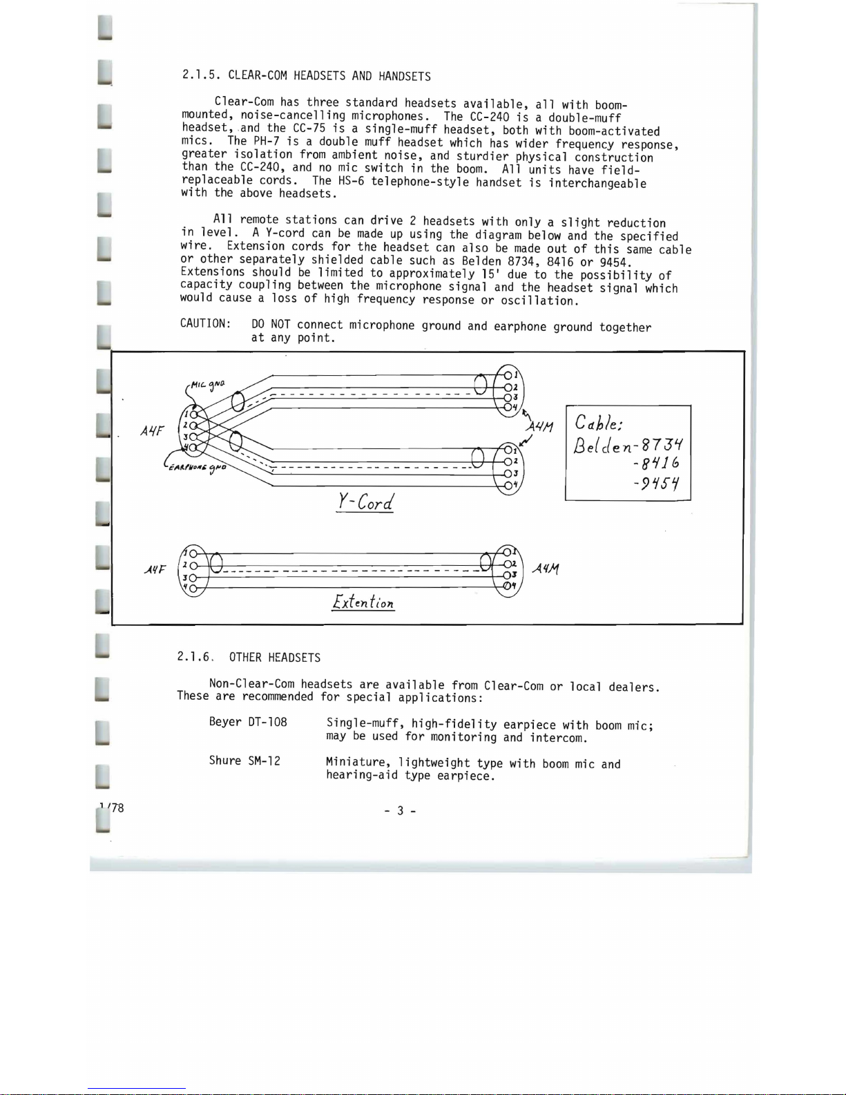
All remote
stations
can drive 2 headsets with only a
slight
reduction
in
level. A V-cord
can
be
made
up
using the diagram
below
and
the specified
wire. Extension cords for the headset
can
also
be
made
out
of
this
same
cable
or other separately shielded cable such as Belden 8734,
8416
or 9454.
Extensions should
be
limited to approximately 15'
due
to the
possibility
of
capacity coupling
between
the microphone signal
and
the headset signal
which
would
cause a loss
of
high
frequency response or
oscillation.
CAUTION:
DO
NOT
connect microphone
ground
and
earphone
ground
together
at
any
poi
nt.
A/.{F
I
..
-
C
dble:
B
e{
c{
en
- g7
31.(
-8Jflb
-9~S1
Y-Cord
2.1.6 .
OTHER
HEADSETS
Non-C1ear-Com
headsets are
available
from
Clear-Com
or local
dealers.
These
are
recommended
for special
applications:
Beyer
DT-108
Single-muff,
high-fidelity
earpiece with
boom
mic;
may
be
used
for
monitoring
and
intercom.
Shure
SM-12
Miniature, lightweight type with
boom
mic
and
hearing-aid type earpiece.
, '78
- 3 -
Page 5
2.1.6
INTERFACE
TO
OTHER
COMMUNICATION
SYSTEMS
The
AC-10
Adapt-a-Com
is
a universal adapter
which
enables
Clear-Com
to
be
interfaced with
any
other intercom or communications
link.
When
existing
non-Clear-Com
installations
are being
upgraded
to
Clear-Com
equipment, portions of the older system
can
be
retained. Since
Adapt-a-Com
works
in 2-, 3-and
4-wire systems,
it
virtually
guarantees compatibility
with
any
house
intercom equipment.
Because
it
will simulate a carbon mic,
Adapt-a-Com
can
be
plugged
into the headset jack
on a TV
camera, control
unit,
or other 2-wire systems.
Adapt-a-Com
operates with telephone
company
and
competitive
model
3-wire
intercoms,
facilitates
on-line intercom via standard telephone systems,
and
aids in
direct
communication
between
the studio
and
remote locations via
2 or 4 wire dedicated
TEL.CO.
pairs.
2.1.7
AUDIO
ISOLATION
OF
PARTS
OF
THE
INTERCOM
SYSTEM
In
certain
applications,
it
may
be
desireable to
isolate
conversations
in
one
section
of
the system.
In
these instances, the
BA-l
in-line
isolator
may
be
used
to block audio while allowing
power
to
flow
to the
isolated
leg
of
the system. This inexpensive, passive device
creates
a quasi-dual channel
system
from
a single channel, except
that
the
main
station
cannot contact or
be
called
by
the
isolated
leg of the system.
The
BA-l
enables
you
to
have
private local conversations along a
common
interconnect cable without
need
for multiple cabling or several
main
stations.
Any
number
of
BA-lls
may
be
used,
so
long as the
power
capacity
of
the
main
station
is
not exceeded.
2.2
MAXIMUM
NUMBER
OF
STATIONS
AND
CABLE
CONSIDERATIONS
2.2.1
MAIN
STATION
CURRENT
AND
IMPEDANCE
LIMITS
All
Clear-Com
main
stations,
induding
the
PS-3000
power
supply,
have
the
same
maximum
output current capacity, 2
amps.
For
dual channel
main
stations,
the
total
current
draw
on
both channels cannot exceed 2
amps.
Due
to
impedance
considerations, regardless of the cable lengths or
mix
of
remote
stations,
40
stations
are the
maximum
that
can
be
driven
from
one
main
station.
(In
certain
circumstances,
it
may
be
possible to
use
more
than
40
stations;
contact the factory
for
details.)
2.2.2
CALCULATING
THE
MAXIMUM
NUMBER
OF
REMOTE
STATIONS
In
installations
with less than
500
feet
total
interconnecting cable,
only the
remote
station
current requirements
need
be
considered.
One
main
station
will support
up
to
40
RS-100A
or
MR-102
remote
stations,
or
up
to
15
KB-100
or KB-lll remote
stations.
1/78
- 4 -
Page 6
1/78
When
calculating
the
maximum
current
drain,
only
two
figures
need
be
considered; a
maximum
current
drain
of
40
ma
in the
RS-100A
or
MR-102,
and
an
average
current
drain
of
130ma
in the
KB-100
or KB-lll. Thus,
an
equation
for
maximum
stations
would
be
as follows:
x =
Number
Of
RS-100A's +
MR-102
1
s <40.
Y
=
Number
of
KB-l
00
I s +
KB-
111
IS
< 15.
Therefore,
0.04X + 0.13Y
~
2.0
2.2.3
CABLES
Where
cable lengths
greater
than
500
feet
are
involved, the
maximum
number
of remote
stations,
depends
on
four
factors;
the
current
requirements
of
each remote
station,
the length
of
the
wire,
the wire gauge,
and
the cable
capacitance.
In
all
instances,
2-conductor,
shielded
interconnecting
cable
should
be
used.
A.
PORTABLE
INSTALLATIONS:
rubber-insulated
and
jacketed
cable should
be
used
due
to
its
superior
strength
and
durability.
Belden
8413
mini-
ature
cable
(24
gao
stranded conductors)
is
usable
up
to
500
feet.
Belden
8412
(20
gao
stranded conductors)
is
usable
up
to 5,000
feet.
B.
PERMANENT
INSTALLATIONS:
Vinyl-insulated
and
jacketed
cable
may
be
used;
it
costs
less
and
is
easier
to
pull through conduit than
rubber
insulated
types.
However,
low
capacitance
cable
must
be
used.
Belden
8762
(20
gao
stranded conductors)
is
usable
up
to
500
feet.
Belden
S'1rA
(18
gao
stranded conductors)
is
usable
up
to 5,000
feet.
NOTE:
In
systems where conduit
is
not used,
and
where equipment
may
not -share a
common
ground,
it
may
be
necessary
to
run
an
additional
ground wire
to
tie
chassis
together.
This
may
be
accomplished with
Belden
8770
3-conductor
shielded
cable.
C.
2-CHANNEL
PERMANENT
INSTALLATIONS:
Permanent systems can
be
wired in
one
of
two
ways.
First,
Channel A
and
Channel B may
be
routed to
two
distinct
areas,
for
use
by
different
people. Second,
both channels
may
be
routed
together
and
brought to
WP-2
wall
plates
so the user
can
select
either
channel A
or
B.
The
second
method
can
be
wired with
two
2-conductor
shielded
cables
or
one
multi-pair
shielded
cable.
Cables
equivalent
to
the
Belden types
may
be
used, so long as
their
capacitance
and
wire gauge
are
comparable.
Particularly
in longer runs,
it
is
desirable
to
use cable
which
has
low
resistance
(large
diameter conductors)
and
low
inter-conductor
capacitance.
- 5 -
Page 7

2.3
LAYING
OUT
THE
SYSTEM
2.3.1
PORTABLE
INSTALLATIONS
Having
determined the
number
and
type
of
remote
stations
you
wish
to use, decide
on
a location for the
main
station.
It
should
be
near a
source of
115V
AC
(power
consumption
is
app
roximately
80
watts.)
There
are
six
parallel
outputs availab
le
on
the
rear
panel of the
CS-100,
and
two
sets
of 3 parallel
outputs
on
the
CS-200.
Any
remote
sta
t ions
can
be
connected
directly
to the 6 outputs. Additionally, remote stat
ions
can
be
added
by
"daisy chaining"
them
to
one
another and/or
by
using the
QP-100
Quadrapuss
splitter.
Cables should
be
routed
away
from
heavy
AC
power
sources,
such
as
lighting
panels,
electric
motors,
etc.
2.3.2
PERM'ANENT
INSTALLATIONS
The
same
general considerations apply here
as
for
portable systems,
as
described in the preceding paragraph. Additionally, cables should
be
installed
in accordance with approved local building codes. Class II
wiring
may
be
used. Connections to
wall-plates
or wall-mount remote
stations
are
shown
in the di agrams.
2.3.3
ISOLATED
CHANNELS
The
BA-l
In-Line
Isolator
can
be
installed
anywhere
in the system.
For
example, plug
it
into
one
output connector
on
the
rear
panel of the
main
station
to create
an
entire
isolated
channel.
Alternately,
plug
it
into a remote
station
at
the
end
of a cable
run
to
isolate
further
remote
stations
while using a
minimum
of
additional interconnect cable.
Typical
Coliseum
Intercom
System
- 6 -
1/78
Page 8

OPERATION
OF
THE
SYSTEM
OPERATION
OF
THE
CLEAR-COM
SYSTEM
IS
QUITE
SIMPLE,
AS
FOLLOWS:
1.
CONNECT
MAIN
STATION
to
all
remote
stations
with interconnecting cable.
NOTE:
Before connecting
rear
panel interconnecting
cables,
shut
power
off
and
hold
call
button depressed
until
call
light(s}
go
out.
2.
PLUG
IN
HEADPHONES
at
main
station
and
remote
stations
into
HEADSET
CONNECTORS
at
front
panel.
(To
locate
connectors
and
controls,
see Figure
l.)
Headset connectors in
main
station
are wired in
parrallel.
Use
one
or
both.
3.
SE
T
I~ASTER
GAIN
SET
at
rear
panel of
main
station
for
overall system level to
compensate
for
number
of
remote
stations
in system.
(CS-200
has
one
gain control
for
each channel.)
Under
high noise
conditions,
turn master gain
DOWN
and
speak
with microphone very close to the
mouth.
4.
SET
HEADSET
VOLUME
CONTROLS
at
main
station
and
remote
stations
for
individual
volume
level.
Volume
controls
are located
on
front
panel.
5.
TO
SIGNAL
stations
where
headphones
may
have
been
removed, press
CALL
BUTTON
on
front
panel
and
CALL
LIGHT
will
go
on. Call
lights
light
up
at
all
stations
simultaneously.
6.
THE
AUXILIARY
INPUT
CONNECTOR
on
front
panel
of
the
main
station
provides
for
external
program
feeding
into
the
entire
system. (See schematics
for
connecting
details).
The
AUXILIARY
VOLUME
CONTROL
is
located
directly
on
top
of
the
auxiliary
input connector
and
controls the
auxiliary
input
volume
to the system.
7.
THE
CS-200
MAIN
STATION
can
communicate
with
two
separate channels, A
and
B.
THE
CHANNEL
SELECT
SWITCH
which
is
located
on
the
front
panel
of
the
main
station,
can
be
switched to
positions
A, B or
A +
B.
The A or
B position
enables the
main
station
to
communicate
with
either
channel A
or
B,
respectively,
while the A + B
position
enables the
main
station
to
communicate
with both
simultaneously. Regardless
of
the
position
of the switch, remote
stations
on
channel A
can
always
talk
to
other
remote
stations
on
A,
but A cannot communicate
with remote
stations
on
channel
B,
and
vice-versa.
Also, note
that
the
call
lights
are always operative
from
main
station
to both channels A
and
B,
regardless
of
the switch
position.
8.
CAUTION:
A}
DO
NOT
allow
belt
packs
to
come
into
contact with
other
pieces
of
electrical
equipment.
An
improper ground
or
short
in a piece
of
electrical
equipment touching a
Clear-Com
remote
station
can
cause a
hum
or a
buzz
in the system.
When
connecting remote
stations
to
electrical
equipment,
make
sure the equipment
is
properly grounded.
B}
DO
NOT
wear
the remote
stations
in
wet
weather without ensuring
that
the
station
is
properly grounded.
- 7 -
1/78
Page 9

OPERATION
OF
SYSTEM
PS-3000
INTERCOM
POWER
SUPPLY
DESCRIPTION
The
PS-3000
is
a regulated intercom
power
unit
designed to
power
all
Clear-Com
remote
stations.
Typically,
it
can
be
installed
in areas not
requiring
a headset
function,
i.e.,
isolated
rack bays.
The
PS-3000
su-plies
30v
at 2 amps
and
is
capable
of
supporting a
minimum
of
40
Clear-Com
remote
stations.
It
is
protected
against
shorts
in the cable
by
current
foldback in the
regulator
circuit
and
provides visual
indication
of
such
conditions
on
the
front
panel system. The
unit
has
provisions
for
an
auxillary
program
input to the intercom system with the level
adjustable
from
the
front
panel.
INSTALLATION'
AND
OPERATION
The
PS-3000
can
be
mounted
in a standard
19"
rack. Because the
PS-3000
can
dissipate
a considerable
amount
of
heat,
it
is ,recommended
that
at
least
an
inch of space
be
allowed
above
the
unit
to
facilitate
ventilation.
All
interconnections to the
unit
are
made
from
the
rear
panel.
Four
parallel
D3M
connectors are provided
for
system output.
As
in
any
Clear-Com
system,
the
lines
to
the remote
stations
may
be
"home-runs"
or
the
stations
may
be
"daisy chained."
Once
the system
has
been
set
up, the overall level
may
be
adjusted with system level
control.
If,
at
any
time,
short
circuit
conditions
are
encountered, the problem
can
usually
be
isollated
by
removing
the interconnect cables
from
the
unit,
one
at
a time, until the
short
circuit
indicator
goes out.
It
may
be
necessary
to shut the
unit
off
for a few
seconds
to
reset
the
short
circuit
indicator.
An
internal
1-1/2
amp
slow-blow fuse
protects
the
PS-3000
in case of
internal
power
supply
failure.
If
the fuse repeatedly
blows,
it
means
the
power
transistor
or a
component
on
the
p.c.
board
has
failed.
The
cover
is
held
on
by
"snap
on"
fasteners.
To
remove
- pull cover
up
hard.
- 8 -
1/78
Page 10

SYMPTOM
1)
System
is
totally
dead,
power
switch
light
doesn't
come
on.
2)
Circuit
breaker
trips
repeatedly or
short
circuit
LED
remains
lit
(PS-3000
only)
3) Oscillation
4)
Call
light
doesn't
work.
5)
Individual
Remote
Station malfunction.
6)
Hum
or
Buzz
in system.
1/78
TROUBLE
SHOOTING
CAUSE
Circuit
breaker open.
A.C.
power
failure.
Shorted or mis-wired
interconnect cable. Defective
remote
unit.
Feedback
caused
by
unused
headset
left
with
mic
on
and
volume
turned
up.
Bulb
burned out.
Faulty remote
station,
headset
or
cable.
Inductive pickup caused
by
close proximity of
main
or
remote
station
to
power
lines
or transformers.
Ground
loop caused
by
improper grounding of system
(See
installation
instructions)
10-ohm
chassis
ground
resistor
(Rl
CS-200)
in
main
station
open.
(Note: This
is
caused
by
the
system ground
coming
in contact
with something
that
is
"hot"
with respect to
main
station
earth ground.
Should
this
occur,
a careful check of the system
ground
and
A.C.
distribution
in
your location
is
recommended.)
- 9 -
REMEDY
Reset
circuit
breaker.
Check
A.C.
power
line.
Remove
cables
from
main
station
one
at
a time
until
faulty
line
is
isolated.
Check
for
shorts
between
pins 1
and
2.
Turn
off
mics
on
all
unused
headsets.
Unscrew
lens
from
lamp
holder. Replace
lamp
with
GE
327.
Replace suspect
unit
with
known
good
unit.
Defective remote
stations
or
headsets should
be
returned to factory
for
service.
There are
no
user
servicable
parts
in these
units.
Relocate offending
unit.
Reverse
power
cord.
Lift
ground.
Open
main
station
by
removing
2 screws
in handle
and
unscrewing 4
feet.
Slide
off
cover
and
check
10
ohm
resistor
on
the bridge
rectifier
terminal
strip.
If
open, replace
Page 11

SYSTEM
INTERCONNECTION
DIAGRAM
~
D3F
(UQ
~~
\.U0
CS-100
CS-200
PS-3cxx)
.,
./
~
caM
D3M
(UOO
D3M
D3M
D3M
.,
"
~
GJOQ
TO
OTHE~
STATIONS
INTERCONNECT
CABLE
BElLEN
8413
- 10 -
PIN
CONNECTIONS
FOR
CABLE
PIN
1 -
SH
IELD
PIN 2-+28VWS
PIN 3-AUDIO
Page 12

1/78
CS-100/CS-100K
MAIN
STATION
(FRONT
PANEL)
FIGURE
3
POWER
CALL
LIGHT
HEADSET
SWITCH
@
Coli
CALL
BUTTON
VOLUME
CONTROL
Volume
HEADSET
JACKS
* * * * * * * * * * * * * * * * * * * * * * * * * * * * * * *
CS-100/CS-100K
r~AIN
STATION
(BACK
PANEL)
INTERCONNECT
CABLE
FIGURE
4
-
11
-
AUXILIARY
VOLUME
CONTROL
Volume
AUXILIARY
INPUT
CONNECTOR
* * * * * * * *
CIRCUIT
BREAKER
OUTPUTS
©
••
© 0
••
© ©
MASTER
GAIN SET
CORD
~
PUSh~O
reset
Page 13

1/78
CS-200/CS-200K
MAIN
STATION
(FRONT
PANEL)
FIGURE
1
POWER
CALL
LIGHT
HEADSET
AUXILIARY
SWITCH
CHANNEL
A
VOLUME
VOLUME
CONTROL
CONTROL
Volume
@
Call
CALL
CALL
LIGHT
AUXILIARY
BUTTON
CHANNEL
B
INPUT
CONNECTOR
* * * * * * * * * * * * * * * * * * * * * * * * * * * * * * * * * * * * * *
0
0
l"l""
®
:1
c"~nel
'<>eled
\/olU!TI&
-
-
®
®
HEADSET
JACKS
CHANNEL
A-B SELECT SWITCH
CS-200/CS-200K
MAIN
STATION
(BACK
PANEL)
INTERCONNECT
MASTER
GAIN SET
CIRCUIT
OUTPUTS
CHANNEL
A
BREAKER
CHANNEL
A
@
Pusl,...tO
re~et
CHANNEL
B
POWER-+
CORD
FIGURE
2
-
12
-
MASTER
GAIN SET
OUTPUTS
CHANNEL
B
Page 14

REVISIONS
,<'
)"1
J~
LT"
O(SCRIPTION
.o'PPRO'lED
1f>1 :)~~"'TED
1'-
""
1
rp-t:·~~ ~·~-·M·::"r.. S ""\t.1.'-1·I~
iq
Nlc...
I--
r ,,'
"
C'"
I_f
~)\C~w
:l~l-
- - -
-1-1
NP
Pl.
V
OLU
.....
E.
If
1
):
PO~11101.Jh
I
"'"
A
B~ I-I
I
I cp
,\Y'---+--<
~
I
.~~
1
I
'''''''I
111-4146
~I
~-+--
____
BIIIIS,
"
~1
+
c.s
a3
-
1(0)l'I~"Mf
•
...,ut'-
.....
0
"
.1:'
~5
...tf
1it:Z.'3
""
1
-atO
L
__
_
3.,1(
")1
CAL
L
SWITC.H
Rli
15K
4>-.J....
l1
~2.
=-
CI'-i
.
1_,
...r::-
'7103
1
CALL
L
__
~
___
C2.-~~
p.c.
~S~._-..J
CALL
LAMP
~A_1ll1
..wi
.::.!.!.
- - - -
-O~"-
.!~
..!}'~_~"'-6_.§!.
O
!"A
oIliP B
I
1 1
III
--+---
p~ ~p~--------
lHAI..>. A
CI~
CONN~t.~ORS
'r
IK
r
J4
~
I
J6
I
r - -
-..,
1"'-
~S2._
, I'O'oIlR 1
JI-
OA ....
FA; ! I\
'Y
iO
:..
Z.
1 5
1A11101
,
J?
~IIH
'I.
1
___
_ ..J
"
.0"'
....
'"
0'"''
~
(lear
(
.8A
OT"[_I$£
E
~
CIn.
SP£c m(D
-
sa
.-...rcan
.,....,.
rR4CTtON$
ace
....
"GUS
8
L6
l~O
3A&
0 0 C 5 -
2.00
SC.HE.MATIC.:
~CLT
1AP
r
..
PPROVAl> I
"m
(FULL
5"5TEN\
'
IMRi\l;..
1,1-11-111
J
~-
CH£C"['~
1
11
1
,-7'
~AI"
SI7r
nAAWING
NO
I
Page 15

_
~
P\NR
,
SUPPLY
M005
~
\lUV
~
1"
::r
~
B-'
-,
I
r
I
I
I
I
I
I
II Co
I
III
1~v.
'f$~
I
~I
L .2.
~
O
••
•
r
'I
JY
J7
51
["'LL
SWIlOI
I
I-J-
!--
-<>
O~$""-I
-
---+--
--'
(!ILL
L.AlAPI
A
J~
LT"
O(SCRIPTION
.-....0
,<!.
PI
13
I
HVISfD
l~DK
~~
c 1
1'1·',....71
I 1(1(,.
I-
I
I
I
I
I
R2.
I~.
L _ _
. _
':1
5
t::if~
C.I~
.,I
. I
...
f
3,,~1(
o<.n
_
__
!l.3
LI
CBl
\
S~H
jV-;YY''-----1>-----,.
~!t\"
..
----
_tJ
.
.Il!.O
P 3
.r(
I<
71
02.
i
~
___
C~·
~O_p~
~S'i5._....J
r - - - -
~
'
-()
~
~<
"o
'-
~
"'ll(
.
·.J
""\'C~
,.. ...
.
3 :
l,O
I
~CLT
I
C;
TAP
I
F\
.JJAI'O"
...
'"
",,"u
I E
~Ca--
..
C
56
Oh'(_
IS(
'''1:Cl
Ji[
O
~
~-
()fTt.
3A<7
r
,.
...
~fl
O
..
S
0(( ."GUS
~
.......
C S - IOO
SO-\c.N\I\'-\C,
(\=\JLL
SYSTEM)
:.J-
-.j
SCA.l [ • SIZE
~"MMC
NO
Page 16

CS-I00/CS-200
PARTS
LIST
ITEM
PART #
DESCRIPTION
REF.
DES.
CS-I00
CS-200
\1fY. QTY.
1
1800
Choke,
Fi 1 ter
Ll
1 1
2
4805
Diode,
3A
IN5401
07,8,9,10
4 4
3
1523
2000
mfd
35V
Cl,
C2
2 2
4
1529
.01
mf/l.4kV
Capaci
tor
C3
3
3
I
5
5202
.5
Amp
Circuit
Breaker
CBl
1
1
6
3900
Call
Light
Assembly
II,
12
2
1
3901
7
#327
Lamp,
28V.
1 2
8
2113
04M
Connectors
J
1,
J2
2 2
2102
9
03F
Connector
J3
1 1
2103
10
D3r1
Connectors
J4 -J9
6 6
11
250K
Pot
3/8
"
Bushing
4701
PI,
P2
2 2
12
4702
lK
Pot
1/4"
Bushing
P3,
P4
2
1
7103
Amplifier
Modul
e
13
PCl
0
1
14
71 02
Amplifier
Modul
e
PCl
0
1
4102
10
ohm
1/4w
Re
si
stor
Rl
15
1 1
5100
Push
Button
Sl
16
1 1
S2
17
5102
Power
Swi
tch
1
1
Power
Transformer
18
5602
Tl
1
1
6000
Power
Cord
19
1 1
20
3
Position
Lever
Swi
tch/
S3
0
7120
1
Plug
Assembly
2401
1
21
Knob
1
2402
4 4
22
Feet
Page 17

SPECIFICATIONS
CS-100/CS-200
MAIN
STATION
AMPLIFIER:
Solid
State
IC
plug in printed
circuit
amplifier
module
including
signalling
circuit.
Current
limited
and
short
circuit
protected.
FREQUENCY
RESPONSE:
250
Hz -10
KHz
(-3
dB
ref.
to 1
KHz)
with a
rising
response to enhance voice
intelligibility.
HEADSET
MICROPHONE
INPUT
LEVEL:
-55
dBm.
HEADPHONE
OUTPUT
LEVEL:
9 volts
rms
into
600
Jl.maximum.
(-20dBm)
DISTORTION:
Less
than
0.5%.
SYSTEM
IMPEDANCE
AND
LEVEL:
Approximately -25
dBm
into
200
(Level dependent
on
master gain control
settings)
AUXILIARY
INPUT
AUDIO
LEVEL:
100
mv
into
600
Jl.
mi
nimum.
CHANNEL
SEPARATION
(CS-200):
">
45
dB.
HEADSET
INPUT
CONNECTOR:
2 - 4 pin connectors
(D4M)
INTERCONNECT
OUTPUT
CONNECTORS:
CS-100:
6 each in
parallel,
Switchcraft
D3M.
CS-200:
Channel
A:
3
each
in
parallel,
Switchcraft
D3M.
Channel
B:
3
each
in
parallel,
Switchcraft
D3M.
AUXILIARY
INPUT
CONNECTOR:
Switchcraft
D3M.
POWER
SUPPLY:
28
volts
circuit
breaker protected.
CAPACITY:
Will
support
up
to
40
RS-100A
or
MR-102
remote
stations
or 15
KB-100
or KB-lll
remote
stations.
POWER
REQUIREMENTS:
115/230
volts
50-60
Hz.
80
watts
maximum.
DIMENSIONS:
CS-100/CS-200:
9.5"L X
4"H
X 8.5"D.
CS-100K/CS-200K:
19"L X 3.5"H
X 9.125"D.
WEIGHT:
CS-100/CS-200:
6 1 bs.
14
oz.
CS-100K/CS-200K:
6 1 bs.
15
oz.
 Loading...