

Page 1
PRO850 Dual-Receiver Beltpac
b
Second Receiver Module
INSTALLATION INSTRUCTIONS
d devices. Comply with ESD safe handling procedures while following these instructions.
A second receiver added to the PRO850 Dual-Receiver Beltpac allows simultaneous use of two
channels of intercom or one intercom channel plus an IFB. The following instructions will
guide you through installation of a second receiver module in a PRO850 Beltpac.
CAUTION
: Both the second receiver module and the Beltpac contain static sensitive
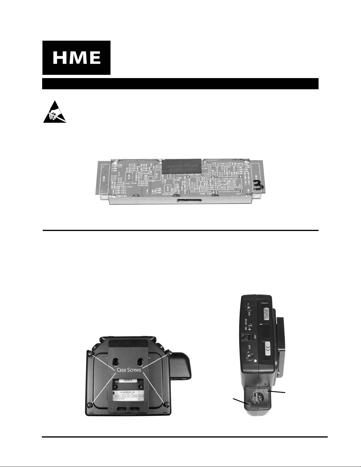
Figure 1. Second receiver module
PROCEDURE
Open the Beltpac and install the second receiver module as follows:
• Unscrew/Remove the two antennas and remove the battery pack from the Beltpac.
• Loosen/Remove the six screws from the Beltpac, shown in Figure 2.
NOTE:
remove) the connector screw shown
below, just enough to open the
Beltpac case, it will hold the metal
If you loosen (but do not
rack et inside the connect or in place.
Loosen this
connector
screw
Figure 2. Remove six screws from Beltpac
HM ELECTRONICS, INC.
14110 Stowe Drive, Poway, CA 92064 USA • Phone: 1-800-848-4468 Fax: (858) 552-0172
Remove this
connector
screw
HME# 400G550
Rev A 2/28/05
Page 2
• Open the Beltpac case.
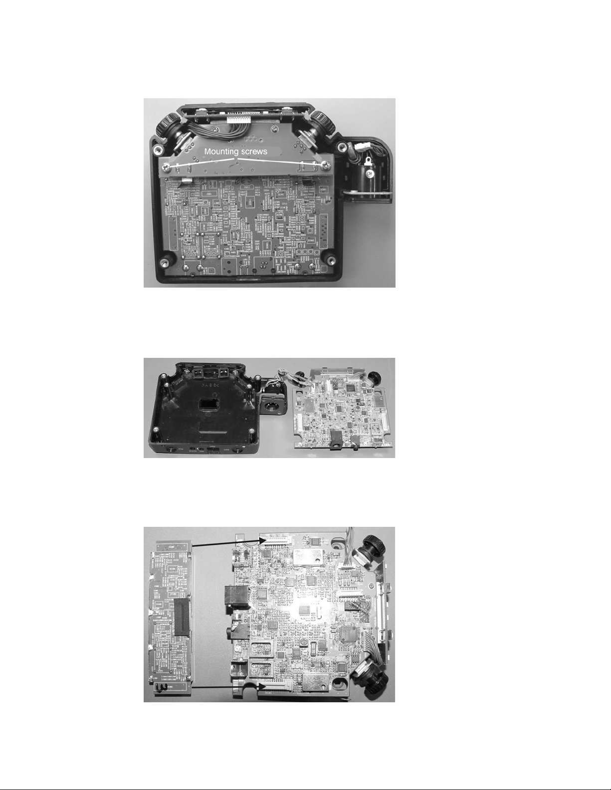
• Remove the two mounting screws from the power supply circuit board as shown
in Figure 3.
Figure 3. Remove mounting screws
• Lift the circuit board assembly out of the Beltpac and set it beside the case as
shown in Figure 4.
Figure 4. Set circuit board assembly next to case
• Install the receiver module on the main circuit board in the position shown in
Figure 5, pressing it firmly onto the two connector plugs.
Figure 5. Install receiver module
NOTE:
polarized, and will only allow the
module to be plugged in one way.
The two connectors are
2
Page 3

Reassemble the Beltpac as follows:
• Insert the circuit board assembly into the Beltpac case at an angle, as shown in
Figure 6, so the remote connector fits into the “RMT” opening at the bottom of
the case, as shown in Figure 7.
Figure 6. Insert board at angle
Figure 7. Fit remote connector into “RMT”
opening at bottom of case
• Route the connector wires between the two standoffs and the plastic tab as
shown in Figure 8.
Figure 8. Routing of connector wires
3
Page 4

• Be sure the rubber switch cover is in place at the top of the case, as shown in
Figure 9. The button portions of the switch cover must protrude through the
two square holes on top of the Beltpac case.
Figure 9. Rubber switch cover position
• Lower the upper edge of the board into the Beltpac case so the rubber gaskets
under the control knobs fit into the grooves on the edge of the case, and the
switches fit under the rubber switch cover as shown in Figure 10. It may be
necessary to carefully guide the edge of the switch cover upward to enable the
switches to slide under the switch cover. Also, be sure the connector wires can
move freely, and are not pinched under the board.
Figure 10. Board placement in case
4
Page 5

• Be sure the circuit board is seated firmly in place as shown in Figure 11.
• Replace the two PCB mounting screws in the positions shown in Figure 11, to
secure the board assembly in place.
Figure 11. Mounting screws in board assembly
• Check the front cover of the Beltpac case to be sure the rubber switch cover in it
is also in place, with its button portions protruding through the two square
holes on its top, as shown by the two arrows in Figure 12.
Figure 12. Rubber switch cover in front cover
of Beltpac case
• Fit the front and back covers of the Beltpac case together, assuring that the
metal plate inside the headset connector fits properly into the respective groove
in the front cover. Snap the covers securely into place. NOTE: Be sure the A
and B button covers do not fall out of position as you fit the covers together.
• Replace the six screws shown in Figure 2.
• Replace the antennas and battery pack.
5
Page 6

Figure 13. Put label on Beltpac
• Put the enclosed self-adhesive label on the Beltpac in the position shown
in Figure 13.
Check controls and switches as follows:
• Rotate the two control knobs to be sure they move freely.
• Press switches A, B, C and D, to be sure they click when pressed.
• Turn the power on. Be sure both A and B indicator lights shown in Figure 14
are lit, indicating both receivers are operating.
Figure 14. Be sure A and B indicator lights are lit
6
 Loading...