

Page 1

CLEAR-COM ECLIPSE
AES-6 DIGITAL INTERFACE
INSTRUCTION MANUAL
Page 2

AES-6 Digital Interface Instruction Manual
© 2008 Vitec Group Communications Ltd. All Rights Reserved.
Part Number 810383Z Rev. 2
Vitec Group Communications LLC
850 Marina Village Parkway
Alameda, CA 94501
U.S.A
Vitec Group Communications Ltd
7400 Beach Drive
IQ Cambridge
Cambridgeshire
United Kingdom
CB25 9TP
Vitec Group Communications
Room 1806, Hua Bin Building
No. 8 Yong An Dong Li
Jian Guo Men Wai Ave
Chao Yang District
Beijing, P.R. China 100022
® Clear-Com, CellCom/FreeSpeak and the Clear-Com Communications Systems logo are registered trademarks of
The Vitec Group plc.
Page 3

CONTENTS
OPERATION . . . . . . . . . . . . . . . . . . . . . . . . . . . . . . 1-1
Introduction. . . . . . . . . . . . . . . . . . . . . . . . . . . . . . . . . . . . . . . . . . . .1-1
Description . . . . . . . . . . . . . . . . . . . . . . . . . . . . . . . . . . . . . . . . . .1-1
Operation . . . . . . . . . . . . . . . . . . . . . . . . . . . . . . . . . . . . . . . . . . . . .1-2
Power LED . . . . . . . . . . . . . . . . . . . . . . . . . . . . . . . . . . . . . . . . . .1-3
Status LED . . . . . . . . . . . . . . . . . . . . . . . . . . . . . . . . . . . . . . . . . .1-3
Panel Connectivity . . . . . . . . . . . . . . . . . . . . . . . . . . . . . . . . . . . .1-5
Port Configuration Switches . . . . . . . . . . . . . . . . . . . . . . . . . . . . .1-6
Data Port. . . . . . . . . . . . . . . . . . . . . . . . . . . . . . . . . . . . . . . . . . . .1-7
Reset Button . . . . . . . . . . . . . . . . . . . . . . . . . . . . . . . . . . . . . . . . .1-7
INSTALLATION . . . . . . . . . . . . . . . . . . . . . . . . . . . . 2-1
Introduction. . . . . . . . . . . . . . . . . . . . . . . . . . . . . . . . . . . . . . . . . . . .2-1
Installation In Interface Frame . . . . . . . . . . . . . . . . . . . . . . . . . . . . .2-1
Connecting the Rear Cards . . . . . . . . . . . . . . . . . . . . . . . . . . . . . . .2-1
AES-6-CX Interface Card . . . . . . . . . . . . . . . . . . . . . . . . . . . . . . .2-1
AES-6-RJ Interface Card . . . . . . . . . . . . . . . . . . . . . . . . . . . . . . .2-3
Mono Configuration . . . . . . . . . . . . . . . . . . . . . . . . . . . . . . . . . .2-4
Stereo Configuration . . . . . . . . . . . . . . . . . . . . . . . . . . . . . . . . .2-5
Cable Pinouts . . . . . . . . . . . . . . . . . . . . . . . . . . . . . . . . . . . . . . . .2-8
Vitec Group Communications
AES-6 Digital Interface Instruction Manual
MAINTENANCE. . . . . . . . . . . . . . . . . . . . . . . . . . . . 3-1
SPECIFICATIONS. . . . . . . . . . . . . . . . . . . . . . . . . . 4-1
AES-6 Digital Interface . . . . . . . . . . . . . . . . . . . . . . . . . . . . . . . . . . .4-1
LIMITED WARRANTY. . . . . . . . . . . . . . . . . . . . . . . W-I
Warranty Period . . . . . . . . . . . . . . . . . . . . . . . . . . . . . . . . . . . . . . . .W-i
Technical Support. . . . . . . . . . . . . . . . . . . . . . . . . . . . . . . . . . . . . . .W-i
Warranty Repairs and Returns . . . . . . . . . . . . . . . . . . . . . . . . . . . . W-ii
Non-Warranty Repairs and Returns . . . . . . . . . . . . . . . . . . . . . . . . W-ii
Extended Warranty. . . . . . . . . . . . . . . . . . . . . . . . . . . . . . . . . . . . .W-iii
Liability . . . . . . . . . . . . . . . . . . . . . . . . . . . . . . . . . . . . . . . . . . . . . .W-iii
i
Page 4

ii
AES-6 Digital Interface Instruction Manual
Vitec Group Communications
Page 5

Please read and follow
these instructions
before operating this
product.
IMPORTANT SAFETY INSTRUCTIONS
1. Read these instructions.
2. Keep these instructions.
3. Heed all warnings.
4. Follow all instructions.
5. Do not use this apparatus near water.
6. Clean only with dry cloth.
7. Do not block any ventilation openings. Install in accordance with
the manufacturer’s instructions.
8. Do not install near any heat sources such as a radiators, heat
registers, stoves, or other apparatus (including amplifiers) that
produce heat.
9. Only use attachments/accessories specified by the manufacturer.
10. Use only with the cart, stand, tripod, bracket, or table specified by
the manufacturer, or sold with the apparatus. When a cart is used,
use caution when moving the cart/apparatus combination to avoid
injury from tip-over.
11. Unplug this apparatus during lightning storms or when unused for
long periods of time.
12. Refer all servicing to qualified service personnel. Servicing is
required when the apparatus has been damaged in any way, such
as power-supply cord or plug is damaged, liquid has been spilled
or objects have fallen into the apparatus, the apparatus has been
exposed to rain or moisture, does not operate normally, or has
been dropped.
13. WARNING: To reduce the risk of fire or electric shock, do not
expose this product to rain or moisture.
Vitec Group Communications
AES-6 Digital Interface Instruction Manual
Please familiarize yourself with the safety symbols in Figure 1. When
you see these symbols on this product, they warn you of the potential
danger of electric shock if the station is used improperly. They also
refer you to important operating and maintenance instructions in the
manual.
iii
Page 6
CAUTION
RISK OF ELECTRIC SHOCK
DO NOT OPEN
This symbol alerts you to the presence of uninsulated dangerous
voltage within the product's enclosure that might be of sufficient
magnitude to constitute a risk of electric shock. Do not open
the product's case.
This symbol informs you that important operating and maintenance instructions are included in the literature accompanying
this product.
Figure 1: Safety Symbols
EMC AND SAFETY
The GPI-6 General Purpose Inputs Interface meets all relevant CE and
FCC specifications set out below:
EN55103-1 Electromagnetic compatibility. Product family standard for
audio, video, audio-visual, and entertainment lighting control app aratus
for professional use. Part 1: Emissions.
EN55103-2 Electromagnetic compatibility. Product family standard for
audio, video, audio-visual, and entertainment lighting control app aratus
for professional use. Part 2: Immunity.
And thereby compliance with the requirement of Electromagnetic
Compatibility Directive 2004/108/EC and Low Voltage Directive
2006/95/EC
This device complies with Part 15 of the FCC Rules. Operation is
subject to the following two conditions: (1) this device may not cause
harmful interference, and (2) this device must accept any interference
received, including interference that may cause undesired operation.
iv
AES-6 Digital Interface Instruction Manual
Vitec Group Communications
Page 7

1
OPERATION
INTRODUCTION
This chapter describes how to use the AES-6 Digital Interface. You can
use this chapter once the Eclipse matrix system has been correctly
installed and configured with the Eclipse Configuration System. To
configure an Eclipse system with AES-6 interfaces Eclipse
Configuration System (ECS) software V4.2 or later is required.
Some of the facilities described in this manual require the AES-6 to be
running Eclipse V5.0 or later firmware.
For information on configuring the AES-6 please refer to Chapter 2
“Installation”.
DESCRIPTION
The AES-6 digital interface consists of a front card with indicators for
power , status and connectivity and four DIP switches for configuration.
A 3.5mm jack socket for software update and a recessed reset button
are also present on the front card. Two rear cards also form p art of the
AES-6 digital interface; the AES-6-RJ and the AES-6-CX. The
AES-6-RJ rear card provides twelve RJ-45 ports and the AES-6-CX
rear card provides six RJ-45 ports and six BNC ports. Each rear card
requires a separate AES-6 front card.
The AES-6-RJ rear card is used to connect up to six AES sources with
RJ45 interfaces to an Eclipse system using CAT5 cable.
The AES-6-CX rear card is used to provide up to six mono connections
between digital panels fitted with coax interfaces and an Eclipse
system. Coax cable is used from the panel to the AES-6-CX and CA T5
cable from the AES-6-CX to the Eclipse matrix card. Only V-Series
panels fitted with the AES-3 options card and Eclipse 4000 panels
fitted with the PDE4536 options card are supported by AES-6. Digital
ICS panels (designated by “T” number) such as the ICS-52T and
ICS-92T are not supported by the AES-6 interface.
The AES-6 front card will auto-detect the type of rear card fitted and
adapt to driving a panel interface or 3rd party interface accordingly.
The AES-6 interface will also automatically detect whether a 96KHz
AES data stream is being received or a data stream at 48KHz or lower
and adjust the codecs transparently.
Vitec Group Communications
AES-6 Digital Interface Instruction Manual
1-1
Page 8
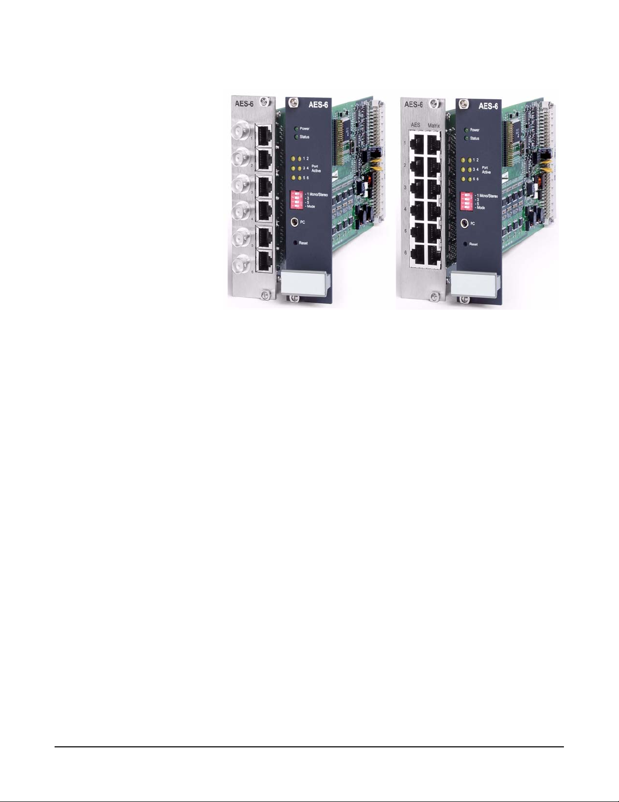
Figure 1-1: AES-6 Digital Interface Cards
The AES-6 digital interface occupies one slot in an IMF-3 or IMF-102
interface module frame or a Median matrix. Connections to the
Eclipse matrix are via 8-pin RJ-45 connectors on the rear panel.
Connections to the panel may either be via RJ-45 and CAT5 cable or
BNC and coax cable depending on the rear card fitted.
OPERATION
In normal use, the AES-6 digital interface does not require operator
interaction. The front panel features CPU and port status indicators,
switches to set stereo feeds, a power indicator LED, a port for
connecting to a PC and a recessed reset switch.
1-2
AES-6 Digital Interface Instruction Manual
Vitec Group Communications
Page 9
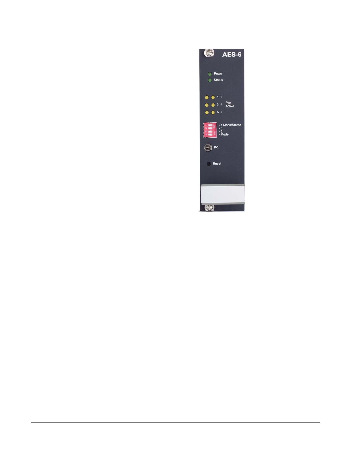
Figure 1-2: AES-6 Front Interface Card
POWER LED
The green power indicator LED lights when DC power is supplied to
the interface. The interface is powered by the interface rack or Median
matrix.
STATUS LED
The green status LED indicates CPU activity on the card. This LED
will indicate if the card CPU is functioning correctly. The status LED
flash modes are:
Vitec Group Communications
AES-6 Digital Interface Instruction Manual
1-3
Page 10
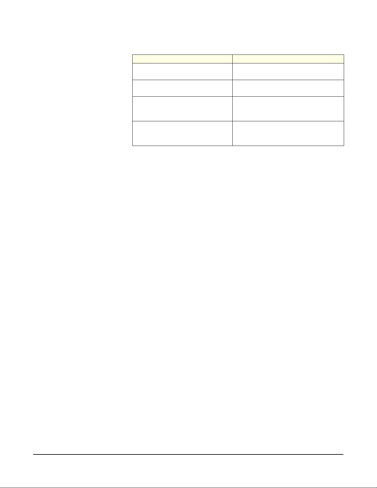
CPU STATUS LED STATE MEANING
Off Card software failed to boot
Slow flash (approx 1Hz) 50:50 Software is running OK
Quick blink flash (approx 1Hz )
25:75
Fast flash (approx 5Hz) 50:50
Table 1-1: CPU Status Codes
FPGA image download in progress
Software has detected a hardware
failure.
Note: The flash ratios in the table are the mark/space ratio for the
LED flashing.
If the FPGA image fails during card bootup the FPGA image will be
erased and the AES-6 will prompt for a new FPGA image to be
downloaded by switching the CPU status LED and all six ports L EDs to
quick blink mode.
During a FPGA download the six port LEDs will flash in a rotating
display with one LED lit at a time until the download stops. The
sequence (by port number) is 2-4-6-5-3-1. When the flash
programming is complete the AES6 card will reboot.
Hardware errors are indicated by the CPU LED flashing rapidly
together with various port LEDs which constitute the fault code. The
current fault codes are given in the table below.
1-4
AES-6 Digital Interface Instruction Manual
Vitec Group Communications
Page 11

CPU LED CODE LED 1 LED 2 LED 3 LED 4 LED 5 LED 6 MEANING
Flash 1 Flash Off Off Off Off Off RAM test fail
Flash 2 Off Flash Off Off Off Off Corrupt Code Image
Flash 3 Flash Flash Off Off Off Off
FPGA Flash Erase
Fail
Flash 4 Off Off Flash Off Off Off FPGA Load Fail
Flash 5 Flash Off Flash Off Off Off FPGA Test Fail
Flash 6 Off Flash Flash Off Off Off UART Check Fail
Flash 7 Flash Flash Flash Off Off Off
UART Local Loop
Fail
Flash 8 Off Off Off Flash Off Off Not Used
Flash : Flash Flash Off Flash Off Off Not Used
FPGA Image
Flash 63 Flash Flash Flash Flash Flash Flash
missing, waiting for
download
Table 1-2: AES-6 Hardware Fault Codes
PANEL CONNECTIVITY
The amber port status LEDs on the front panel display the connection
status of each port on the rear card. If a panel connection is detected
on a port the status LED for that port lights continuously.
In mono mode each LED shows the status of the port as described in
Table 1-3. In stereo mode the LEDs operate in pairs reflecting the
pairing of the ports. The first LED in each pair (LED 1,3 and 5)
provides the connection status for the primary channel as described for
mono mode (Table 1-3) while the second LED in the pair will flash at
1Hz with a mark:space ratio of 25:75 indicating that the port is in stereo
mode. This will occur as a result of the DIP switch setting rather than a
connection and the LED will flash even if nothing is connected to the
primary port.
Vitec Group Communications
AES-6 Digital Interface Instruction Manual
1-5
Page 12

LED STATE (PORTS
1-6)
PANEL MODE USAGE THIRD PARTY USAGE
Off No panel connected or panel failed
No equipment connected or
equipment failed
On Panel connected OK AES source connected
Flash 1Hz
Panel connected but no matrix
connection
Third party mode selected, no AES
connection
Fast Flash Fault, see table Table 1-1 96K detected
LED1 = primary status
LED2=Flash
Stereo mode
Primary Channel status as above
Secondary channel flash 1Hz 25:7 5
Table 1-3: Part Status LEDs
Stereo mode
Primary Channel status as above
Secondary channel flash 1Hz 25:75
PORT CONFIGURATION SWITCHES
There are four DIP switches for port configuration on the front p anel o f
the AES-6 interface (Figure 1-2). Three of the DIP switches configure
the rear card ports between mono and stereo modes. The fourth DIP
switch (Mode) is used to configure the card for either Clear-Com
panels (OFF) or third party equipment (ON).
An AES-6 interface can only be configured for either Clear-Com panels
or third party equipment; Clear-Com panels and third party equipment
cannot be mixed on a single AES-6 interface.
Each of the first three DIP switches corresponds to a pair of ports on
the rear card which may be set up as two monaural audio ports (OFF)
or a single stereo port (ON). When a DIP switch is set for stereo mode
the first port in the pair acts as the primary channel while the second
port acts as the secondary channel and the port LED will flash to
indicate this. The possible DIP switch settings are shown in Figure 1-3
and Figure 1-4.
1-6
AES-6 Digital Interface Instruction Manual
Vitec Group Communications
Page 13

Figure 1-3: AES-6 DIP Switch Settings for Clear-Com Panels
Figure 1-4: AES-6 DIP Switch Settings for Third Party Equipment
DATA PORT
The data port is a 3.5mm jack socket allowing the AES-6 to be
connected to a PC for software/diagnostics download. To connect to a
PC a PD4007 download cable is required.
Vitec Group Communications
AES-6 Digital Interface Instruction Manual
RESET BUTTON
The reset button is behind a hole in the front panel to prevent it being
accidentally pressed. To press the reset button insert a narrow rod or
stiff piece of wire such as a paper clip through the hole to press the
reset button.
1-7
Page 14

1-8
AES-6 Digital Interface Instruction Manual
Vitec Group Communications
Page 15

2
INSTALLATION
INTRODUCTION
This chapter describes the installation of the AES-6 digital interface,
including setting DIP switches and wiring to external devices.
INSTALLATION IN INTERFACE FRAME
To install the AES-6 digital interface module in the IMF-3 or IMF-102
interface frame or Eclipse Median:
1. Select a slot in which to install the interface.
2. Remove the blank plate covering the slot.
3. Slide the AES-6 front card in the front slot and ensure that the card
is fully seated.
4. Select the required AES-6 rear card and slide it into the rear slot
corresponding to the AES-6 front card and ensure that the card is
fully seated.
5. Tighten the AES-6 front panel mounting screws.
6. Tighten the AES-6 rear panel mounting screws.
Note: When hot-plugging any other card in the IMF-3 interface
frame all AES-6 cards in the interface frame should be reset
to ensure correct operation.
CONNECTING THE REAR CARDS
The rear card connections will depend on the type of rear card fitted
and the type of panel or audio link required.
AES-6-CX INTERFACE CARD
The BNC interface rear card provides six RJ-45 ports for connection to
an Eclipse matrix and six BNC ports for connection to 4000 Series II
panels fitted with the PDE4536B interface option, V-Series main
panels fitted with the AES-3 interface option or third party equipment.
These cards may be configured for monaural or stereo use. The 4000
Series II panel types supported by this card are:
• 4224E
• 4215E
• 4226E
Vitec Group Communications
AES-6 Digital Interface Instruction Manual
• 4294E
• 4212E
2-1
Page 16

• 4222E
The V-Series panel types supported by this card are:
• V12LD
• V12PD
• V24LD
• V24PD
• V12LDD
This card is for use with installation where the data connections to the
4000 Series II and V-Series panels or third party equipment are made
using coaxial cable rather than CAT5 cable. Each audio source is
connected to a BNC port on the card and the corresponding RJ-45 port
is connected to a port on a matrix serial port. All format conversion
between the 4000 Series II or V-Series panel and the matrix is carried
out by the AES-6 card.
2-2
Figure 2-5: AES-6-CX Card Connected for Mono
For stereo use i.e. separate left and right ear audio streams only half
the BNC ports can be used with the panels being connected to
alternate BNC ports. For each stereo BNC connection two RJ-45
matrix connections are required which must be specially configured in
AES-6 Digital Interface Instruction Manual
Vitec Group Communications
Page 17

ECS. Currently it is required that the pair of matrix ports comprising a
single stereo channel must be adjacent ports.
Figure 2-6: AES-6-CX Card Connected for Stereo
For each BNC port to be connected in stereo mode the front DIP
switch must be set to the ‘ON’ position.
An example of the type of panel that could b e used with the AES-6-CX
card in either mono or stereo mode is the Clear-Com 4222E panel.
AES-6-RJ INTERFACE CARD
The AES-6-RJ rear card has six pairs of RJ-45 ports allowing 4000
Series II panels, V-Series panels with an AES-3 interface and third
party equipment to be connected using CAT5 cable. The third party
equipment may be of any compatible type that provides a digital
interface. These cards may be configured for monaural or stereo use.
Vitec Group Communications
AES-6 Digital Interface Instruction Manual
2-3
Page 18

Mono Configuration
Figure 2-7: AES-6-RJ Connected for Mono Panels
For AES-6-RJ connected panels standard straight through CAT5 cable
may be used to connect panels to the AES-6 interface and the AES-6
interface to the matrix.
2-4
AES-6 Digital Interface Instruction Manual
Vitec Group Communications
Page 19

Figure 2-8: AES-6-RJ Connected for Mono Third Party Equipment
When a matrix port is connected to an AES-6 interface for audio only
operation the matrix port should be configured as “AES Mono” in ECS
(Setup Matrix Hardware).
Stereo Configuration
For stereo use i.e. separate left and right ear audio streams only half
the RJ45 ports can be used with the sources being connected to
alternate ports. For each stereo RJ45 connection two RJ-45 matrix
connections are required which must be specially configured in ECS.
Currently it is required that the pair of ports comprising a single stereo
channel must be adjacent ports. The first port of the pair must be
configured as a V-Series or 4000 Series panel and the second port
must be configured as type “Panel Aux”.
Vitec Group Communications
AES-6 Digital Interface Instruction Manual
2-5
Page 20

Figure 2-9: AES-6-RJ Connected for Stereo Panels
When operating in stereo mode the matrix will send two audio stre ams
to the panel consisting on the main intercom audio and auxiliary audio.
The panel will return the panel microphone audio to the matrix.
Figure 2-10: Stereo Audio Flow in AES-6 Systems
When configuring V-Series panels for stereo mode in ECS the Audio
Mixer should be set to “Layout Binaural coax/AES” or “Layout Binaural
coax/AES using D25”. For Elcipse 4000 series panels the appropriate
links must be configured on the main PCB and PDE4536B card. Refer
to the Eclipse 4000 panel installation guide p art STA0530 rev 4 or later
for information on stereo configuration.
2-6
AES-6 Digital Interface Instruction Manual
Vitec Group Communications
Page 21

Figure 2-11: AES-6-RJ Connected for Stereo Third Party Equipment
V-Series panels with AES-3 option cards can also be connected to an
AES-6 interface via an AES-3 compliant network.
Figure 2-12: AES-3 Networking
The V-Serie s panel ES-3 option card uses a data format of 24-bit audio
data and 8-bit user control data. Any AES-3 router used with a
V--Series p anel must not strip of f the user control dat a but must p ass it
through.
Eclipse 4000 panels cannot be networked in this way with PDE4536B
option cards as they use a different form of the AES-3 data structure.
Vitec Group Communications
AES-6 Digital Interface Instruction Manual
2-7
Page 22

CABLE PINOUTS
The CAT5 cables used to connect either type of AES-6 rear card
(AES-6-CX and AES-6-RJ) to a matrix use the following pinout.
PIN NUMBER WIRE COLOR FUNCTION
1 White/Orange Data Transmit (Tx+)
2 Orange Data Transmit (Tx-)
3 White/Green Audio Output (+)
4 Blue Audio Input (+)
5 White/Blue Audio Input (-)
6 Green Audio Output (-)
7 White/Brown Data Receive (Rx+)
8 Brown Data Receive (Rx-)
Table 2-4: AES-6 to Matrix Wiring
Standard straight-through CAT5 cables may be used for this purpose.
The pinout for the CAT5 cable to connect an AES-6-RJ to a panel is
given in the table below.
PIN NUMBER WIRE COLOR FUNCTION
1 White/Orange not used
2 Orange not used
3 White/Green Tx (+)
4Blue Rx (+)
5 White/Blue Rx (-)
6 Green Tx (-)
7 White/Brown not used
2-8
8 Brown not used
Table 2-5: AES-6 to Panel Wiring
AES-6 Digital Interface Instruction Manual
Vitec Group Communications
Page 23

Standard straight-through CAT5 cables may be used for this purpose.
Up to 200m of cable run between the panel or AES source and the
AES-6-RJ interface or between the AES-6 interface and the matrix at a
48K sample rate is possible using 24AWG cable. If 26AWG cable is
used the maximum cable run will be less than 200m.
Note: As the matrix connections are non-isolated the AES-6
interface must be sited local to the matrix and on the same
mains supply.
The specification for the coaxial cable required to connect panels to
the AES-6-CX card is given below.
Nominal
impedance
75 Ohm
Insulation solid polythene
Screen
double braided
copper
Capacitance 68pF/m or better
BBC PSF 1/3M
Equivalents
BICC TM 3304
Brand Rex GT 851
Table 2-6: Coaxial Cable Specification
This type of cable will allow up to 500 metres of cable run between the
AES-6-CX interface and the panel at the standard 48K sample rate.
Vitec Group Communications
AES-6 Digital Interface Instruction Manual
2-9
Page 24

2-10
AES-6 Digital Interface Instruction Manual
Vitec Group Communications
Page 25

MAINTENANCE
3
The AES-6 functional block diagram is shown below.
Vitec Group Communications
AES-6 Digital Interface Instruction Manual
Figure 3-1: AES-6 Functional Block Diagram
3-1
Page 26

3-2
AES-6 Digital Interface Instruction Manual
Vitec Group Communications
Page 27

4
SPECIFICATIONS
AES-6 DIGITAL INTERFACE
0 dBu is referenced to 0.775 volts RMS
Audio
Audio Sample Rate 44.1 kHz - 96.0 kHz
CODEC Resolution 24 bits
Frequency Response 30Hz - 22 kHz ± 3dB
Signal to Noise Ratio < -65 dB (22 - 22kHz filter RMS)
Crosstalk (adjacent channel) < -75 dB @ 1kHz
Nominal Level 0 dBu
Input Impedance > 10 K
Output Impedance 150 R
Headroom +18 dBu
Distortion < 0.1% @ +18 dBu 300Hz - 10 kHz
< 0.5% @ +18 dBu 100 Hz - 20 kHz
Cable lengths
AES-6-CX to Panel Up to 500m using 75 Ohm coax cable
AES-6-RJ to Panel Up to 200m using 24AWG CAT5 cable
AES-6-RJ to AES-3 third party deviceUp to 200m using 24AWG CAT5 cable
Data Format
Audio data 24 bits
User Control data 8 bits
Physical Specifications
Operating Temperature Range 32o to 104o F (0o to +40o C)
o
Storage -22
Humidity 40 - 90% non-condensing
Notice About Specifications
While Clear-Com makes every attempt to maintain the accuracy of the
information contained in its product manuals, that information is
subject to change without notice. Performance specifications included
in this manual are design-center specifications and are included for
customer guidance and to facilitate system installation. Actual
operating performance may vary.
to 158o F (-30o to +70o C)
Vitec Group Communications
AES-6 Digital Interface Instruction Manual
4-1
Page 28

4-2
AES-6 Digital Interface Instruction Manual
Vitec Group Communications
Page 29

LIMITED WARRANTY
Vitec Group Communications (VGC) warrants that at the time of
purchase, the equipment supplied complies with any specification in
the order confirmation when used under normal conditions, and is free
from defects in workmanship and materials during the warranty period.
During the warranty period VGC, or any service company authorized
by VGC, will in a commercially reasonable time remedy defects in
materials, design, and workmanship free of charge by repairing, or
should VGC in its discretion deem it necessary, replacing the product
in accordance with this limited warranty. In no event will VGC be
responsible for incidental, consequential, or special loss or damage,
however caused.
WARRANTY PERIOD
Return Material Authorization
(RMA) numbers are required
for all returns.
Both warranty and
non-warranty repairs are
available.
The product may consist of several parts, each covered by a different
warranty period. The warranty periods are:
• Cables, accessories, components, and consumable items have a
limited warranty of 90 days.
• Headsets, handsets, microphones, and spare parts have a limited
warranty of one year.
• UHF wireless IFB products have a limited warranty of one year.
• UHF wireless intercom systems have a limited warranty of three
years.
• All other Clear-Com and Drake brand systems and products,
including beltpacks, have a limited warranty of two years.
The warranty starts at the time of the product’s original purchase. The
warranty start date for contracts which include installation and
commissioning will commence from the earlier of date of the Site
Acceptance Test or three months from purchase.
TECHNICAL SUPPORT
To ensure complete and timely support to its customers, VGC’s User
Support Center is staffed by qualified technical personnel. Telephone
and email technical support is offered worldwide by the User Support
Center.
Vitec Group Communications
Warranty
The User Support Center is available to VGC’s customers during the
full course of their warranty period.
Instructions for reaching VGC’s User Support Centers are given below.
i
Page 30

T elephone for Europe, Middle East and Africa: +49 40 6688 4040 or
+44 1223 815000
Telephone for the Americas and Asia: +1 510 337 6600
Email: vitec.support@AVC.de
Once the standard warranty period has expired, the User Support
Center will continue to provide telephone support if you have
purchased an Extended Warranty.
For latest contact information please refer to the Service and Support
section at www.clearcom.com.
WARRANTY REPAIRS AND RETURNS
Before returning equipment for repair, contact a User Support Center
to obtain a Return Material Authorization (RMA). VGC representatives
will give you instructions and addresses for returning your equipment.
You must ship the equipment at your expense, and the support center
will return the equipment at VGC’s expense.
For out-of-box failures, use the following contact information:
Europe, Middle East and Africa
Tel: +44 1223 815000 Email:
customerservicesEMEA@vitecgroup.com
North America, Canada, Mexico, Caribbean & US Military
Tel: +1 510 337 6600 Email: customerservicesUS@vitecgroup.com
Asia Pacific & South America
Tel: +1 510 337 6600 Email: customerservicesAP AC@vitecgroup.com
VGC has the right to inspect the equipment and/or installation or
relevant packaging.
For latest contact information please refer to the Service and Support
section at www.clearcom.com.
NON-WARRANTY REPAIRS AND RETURNS
For items not under warranty, you must obtain an RMA by contacting
the User Support Center. VGC representatives will give you
instructions and addresses for returning your equipment.
You must pay all charges to have the equipment shipped to the
support center and returned to you, in addition to the costs of the
repair.
ii
Vitec Group Communications
Warranty
Page 31

EXTENDED WARRANTY
You can purchase an extended warranty at the time of purchase or at
any time during the first two years of ownership of the product. The
purchase of an extended warranty extends to five years the warranty
of any product offered with a standard two-year warranty. The total
warranty period will not extend beyond five years.
Note: VGC does not offer warranty extensions on UHF wireless
intercom systems, or on any product with a 1-year or 90-day warranty.
LIABILITY
THE FOREGOING WARRANTY IS VGC'S SOLE AND EXCLUSIVE
WARRANTY. THE IMPLIED WARRANTY OF MERCHANTABILITY
AND FITNESS FOR A PARTICULAR PURPOSE AND ANY OTHER
REQUIRED IMPLIED WARRANTY SHALL EXPIRE AT THE END OF
THE WARRANTY PERIOD. THERE ARE NO OTHER WARRANTIES
(INCLUDING WITHOUT LIMITATION WARRANTIES FOR
CONSUMABLES AND OTHER SUPPLIES) OF ANY NATURE
WHATSOEVER, WHETHER ARISING IN CONTRACT, TORT,
NEGLIGENCE OF ANY DEGREE, STRICT LIABILITY OR
OTHERWISE, WITH RESPECT TO THE PRODUCTS OR ANY P ART
THEREOF DELIVERED HEREUNDER, OR FOR ANY DAMAGES
AND/OR LOSSES (INCLUDING LOSS OF USE, REVENUE, AND/OR
PROFITS). SOME STATES DO NOT ALLOW THE EXCLUSION OR
LIMITATION OF INCIDENTAL OR CONSEQUENTIAL DAMAGES OR
THE LIMIT ATION ON HOW LONG AN IMPLIED WARRANTY LASTS,
SO THE ABOVE LIMITATIONS MAY NOT APPLY TO YOU. IN ANY
EVENT, TO THE MAXIMUM EXTENT PERMITTED UNDER
APPLICABLE LAW , VGC'S LIABILITY T O CUSTOMER HEREUNDER
SHALL NOT UNDER ANY CIRCUMSTANCES EXCEED THE COST
OF REPAIRING OR REPLACING ANY PART(S) FOUND TO BE
DEFECTIVE WITHIN THE WARRANTY PERIOD AS AFORESAID.
Vitec Group Communications
Warranty
This warranty does not cover any damage to a product resulting from
cause other than part defect and malfunction. The VGC warranty does
not cover any defect, malfunction, or failure caused beyond the control
of VGC, including unreasonable or negligent operation, abuse,
accident, failure to follow instructions in the manual, defective or
improperly associated equipment, attempts at modification and repair
not approved by VGC, and shipping damage. Products with their serial
numbers removed or defaced are not covered by this warranty.
This warranty does not include defects arising from installation (when
not performed by VGC), lightning, power outages and fluctuations, air
conditioning failure, improper integration with non-approved
components, defects or failures of customer furnished components
resulting in damage to VGC provided product.
iii
Page 32

This limited warranty is not transferable and cannot be enforced by
anyone other than the original consumer purchaser.
This warranty gives you specific legal rights and you may have other
rights which vary from country to country.
iv
Vitec Group Communications
Warranty
 Loading...