

Page 1

4000 Series II
User Guide
Issue 1.4
June 2006
Page 2

Page 3

4000 Digital Series II Issue 1.4 Panel User Guide
STA0380 Page i
4000 Series II
Thank you for purchasing this product; we hope it will provide many years of reliable and rewarding
service.
We would be pleased to hear from you if you have any difficulties, comments or suggestions related to
this product, the user documentation or the support servi ce wh ich we o ffer. Plea se feel fr ee to contact
us by e-mail, postal mail or telephone.
Please also visit our website whic is continually being enhanced to offer increased levels of information.
You can find us at http://www.vitecgroupcomms.com/
Vitec Group Communications Limited
7400 Beach Drive
Cambridge Research Park
Cambridgeshire
United Kingdom
CB5 9TP
Page 4

Panel User Guide Issue 1.4 4000 Digital Series II
Page ii STA0380
Page 5

4000 Digital Series II Issue 1.4 Panel User Guide
STA0380 Page iii
General Enquiries: Tel: +44 (0) 1223 815000
Fax: +44 (0) 1223 815001
email: vgc.uk@vitecgroup.com
EMEA Sales: New
Orders:
Tel: +44 (0) 1223 815000
Fax: +44 (0) 1223 815001
email: customerservicesUK@vitegroup.com
Support: Tel: +49 (0) 40 6688 4040 (day)
Tel: +49 (0) 40 6688 4041 (night)
Fax: +49 (0) 40 6688 3055 (repairs)
vitec.support@avc.de (repairs)
vitec.support@avc.de (support)
http://www.avc.de/if/vitec (repairs booking)
Asia Pacific and
South/Central
America Sales:
New Orders: Maria Gonzalez
International Export Coordination
Tel: +1 510 496 6655
Fax: +1 510 496 6699
email: maria.gonzalez@vitecgroup.com
Amado Bautista
International Export Coordination
Tel +1 510 496 6623
Fax: +1 510 496 6699
email: amado.bautista@vitecgroup.com
Jon Ernst
Manager
Tel: +1 510 496 6634
Fax: +1 510 496 6699
email: jon.ernst@vitecgroup.com
Support Richard Spicer
Product Technical Support
Tel: +1 510 496 6662 (office)
Tel: +1 510 381 5001 (mobile)
Fax: +1 510 496 6699
email: richard.spicer@vitecgroup.com
Page 6

Panel User Guide Issue 1.4 4000 Digital Series II
Page iv STA0380
Page 7
4000 Digital Series II Issue 1.4 Panel User Guide
STA0380 Page v
Policy Statement
Vitec Group Communications has a policy of continuous improvement of both products and
documentation and reserves the right modify product specifications and characteristics without notice,
at any time.
Vitec Group Communications has endeavoured to ensure that information, details and descriptions set
out in this document are correct at the time of publication. Where alterations have been made to the
product, we will endeavour to produce appropriate additional information such as supplementary
documents, changes to the website or re-issued copies of a CDROM.
Vitec Group Communications is, however, unable to guara ntee that no changes have taken place to the
specification or characteristics of this product after the publication of this document. Vitec Group
Communications shall not be liable for any loss or damage whatsoever arising from the use of any
information, errors or omissions in this document or any use of the product.
Vitec Group Communications declares that the electronic equipment has been manufactured in
conformity with the following standards:
Trademarks
MS-DOS and Windows are registered trademarks of Microsoft Corporation.
Ethernet is a registered trademark of Xerox Corporation.
© 2006 All rights reserved. Neither the whole, nor any part of the information contained herein, nor in
the products described in this guide, may be adapted or reproduced in any ma terial form except with the
prior written approval of Vitec Group Communications.
European Union Declaration of
Conformity
BS EN 50081-1:1992 Electromagnetic compatibility. Generic
emission standard.
Residential, commercial and light industry.
BS EN 50082-1:1998 Electromagnetic compatibility. Generic
immunity standard.
Residential, commercial and light industry.
BS EN 60950:1992 Safety of information technology equipment.
Page 8

Panel User Guide Issue 1.4 4000 Digital Series II
Page vi STA0380
Page 9
4000 Digital Series II Issue 1.4 Panel User Guide
STA0380 Page vii
Revision History
Issue Date Notes
1.0 November 1999 Initial Issue
1.1 July 2000 Updates
1.2 February 2005 Revisions for new equipment and change to company name
1.3 November 2005 Corrections and updates
1.4 June 2006 Updates for new panels
Page 10

Panel User Guide Issue 1.4 4000 Digital Series II
Page viii STA0380
Page 11
4000 Digital Series II Issue 1.4 Panel User Guide
STA0380 Page ix
Warnings and Cautions
Where appropriate, warnings and cautions appear in the text with the following meanings:
WARNING. Given where carrying out an instruction can cause risk of injury or death.
CAUTION. Given where carrying out an instruction can cause risk of damage to the equipment.
WARNING - EARTHING OF EQUIPMENT
This equipment must be properly earthed.
The mains plug must be connected in accordance with the following code:
• BLUE - Neutral (N)
• BROWN - Live (L)
• GREEN/YELLOW - Earth (E)
As the colours of the wires in the mains lead of this equipment may not correspond with the coloured
markings identifying the terminals in your plug, proceed as follows:
• The wire which is coloured BLUE must be connected to the terminal which is marked with the letter N or is BLACK.
• The write which is coloured BROWN must be connected to the terminal which is marked with the
letter L or is RED.
• The wire which is coloured GREEN and YELLOW must be connected to the terminal which is
marked with the letter E or the symbol
CAUTION - ELECTROSTATIC PROTECTION
When carrying out any maintenance or repair taks on this equipment all personnel should ensure that
appropriate grounding equipment is used and checked before commencing work on the equipment.
Electrostatic sensitive devices are marked with the symbol
GENERAL WARNING
Electrical shock can cause severe personal injury or death. All major units of
this equipment are powered by mains voltage. Unless specifically advised
otherwise, DISCONNECT mains supply before carrying out any maintenance
or repair tasks.
This equipment contains electrostatic sensitive devices. Observe
precautions for handling electrostatic sensitive devices when carrying out
any maintenance or repair tasks.
Page 12

Panel User Guide Issue 1.4 4000 Digital Series II
Page x STA0380
Page 13
4000 Digital Series II Issue 1.4 Panel User Guide
STA0380 Page xi
GLOSSARY OF TERMS
ADC Analogue to Digital Converter
ADM Assignment, Diagnostics and Monitoring
BNC Standard co-axial video connector
CAT5 Cable standard for high speed data communica-
tions (e.g. 100Base-TX)
CODEC Coder/Decoder
CMAPSi Configuration and Master Assignment Program-
ming System integrated
CSU Central Switching Unit
DAC Digital to Analogue Converter
DAK Direct Access Key
dB Decibel
DPDT Double-Pole-Double-Throw
EPROM Erasable Programmable Read-Only Memory
FLASH RAM Low voltage electrically erasable and program-
mable read-only memory.
GPI General Purpose Interface
GPSF General Purpose Special Function
Howlround Distorted audio - due to feedback of original sig-
nal in close proximity.
I/O Input / Output
I/P Input
IFB Interruptible Foldback
Local Programming Modifying the DAK assignments via the Intelli-
gent Control Panel SOFT Mode
LCD Liquid Crystal Display
LED Light Emitting Diode
Listen Route An audio route to the Control Panel from a
source. The audio is normally heard on the Con-
trol Panel's Loudspeaker or Headset.
LS Loudspeaker
Mb Megabyte
MHz Megahertz
N/C Normally Closed
N/O Normally Open
Page 14
Panel User Guide Issue 1.4 4000 Digital Series II
Page xii STA0380
NID Non Intrusive Download
NVRAM Non-Volatile Random Access Memory
O/P Output
PCB Printed Circuit Board
Pot. Potentiometer
PSU Power Supply Unit
RAM Random Access Memory
RCU Rear Connector Unit
RJ45 Standard connector for data communications
(used with CAT5 cabling for comms. between
the matrix and control panels)
RMS Root Mean Square
RU Standard Rack Unit (19 inches wide x 1.75
inches high or 482.6mm x 44.45mm)
Side Tone Side tone is the audio, which is heard in the
Headset's earpiece, which is generated by the
headset microphone. This allows the operators
to hear themselves when using headsets.
SPDT Single-Pole-Double-Throw (switch / relay action)
SPST Single-Pole-Single-Throw (switch / relay action)
TA Terminal Adaptor
Talkback A Broadcast term referring to intercom systems
in which 4-wire comms. are used.
Talk Route An audio route from the Control Panel to another
destination. The audio is normally generated
from the Control Panel's main microphone or
Headset microphone.
TBU Telephone Balance Unit
VOX Voice Operated Switch
XLR Audio industry standard connector
Page 15
4000 Digital Series II Issue 1.4 Panel User Guide
STA0380 Page xiii
Consult the named Vitec Group Communications document for further details.
Contact Vitec Group Communications for suitable options.
Tips given.
Page 16

Panel User Guide Issue 1.4 4000 Digital Series II
Page xiv STA0380
Page 17

Panel User Guide Issue 1.4 4000 Digital Series II
Page i STA0380
Table of Contents
1 Introduction ............................................................................................................1
2 Control Panel Overview .........................................................................................2
3 Control Panel Descriptions ...................................................................................2
3.1 PD4215R (revised) - 16 Key Control Panel (1RU) .......................................................3
3.2 PD4215R - 16 Key Control Panel (1RU) ......................................................................3
3.2.1 Microphone Socket ............................................................................................................. 4
3.2.2 Direct Access Key (DAK) .................................................................................................... 4
3.2.3 Talk Tally LED .................................................................................................................... 5
3.2.4 Listen Tally LED .................................................................................................................. 5
3.2.5 PD4215R Direct Access Key Indicator LED ....................................................................... 5
3.2.6 Designation Strip ................................................................................................................ 6
3.2.7 Microphone Mute Pushbutton ............................................................................................. 6
3.2.8 Main Volume Control ..........................................................................................................6
3.2.9 Loudspeaker ....................................................................................................................... 6
3.2.10 Headset Socket (XLR 5 or DIN 5) ..................................................................................... 6
3.2.11 Headset Select Pushbutton .............................................................................................. 6
3.2.12 Reply Key ................................................ ... .......................................... ... ... .... ... ... ............ 7
3.2.13 Auxiliary Volume Control .................................................................................................. 7
3.3 PD4215 - 16 Key Control Panel (1RU) .........................................................................8
3.3.1 Microphone Socket ............................................................................................................. 8
3.3.2 Direct Access Key (DAK) .................................................................................................... 8
3.3.3 Talk Tally LED .................................................................................................................. 10
3.3.4 Listen Tally LED ................................................................................................................ 10
3.3.5 PD4215 Direct Access Key Indicator LED ........................................................................ 10
3.3.6 Designation Strip .............................................................................................................. 10
3.3.7 Microphone Mute Pushbutton ........................................................................................... 10
3.3.8 Main Volume Control ........................................................................................................10
3.3.9 Loudspeaker ..................................................................................................................... 10
3.3.10 Headset Socket (DIN 5) ..................................................................................................11
3.3.11 Headset Select Pushbutton ............................................................................................ 11
3.3.12 Reply Key ................................................ ... .......................................... ... ... .... ... ... .......... 11
3.3.13 Auxiliary Volume Control ................................................................................................11
3.4 PD4217 - Intelligent Control Panel (1RU) ...................................................................12
3.4.1 Microphone Socket ........................................................................................................... 12
3.4.2 Direct Access Key (DAK) ..................................................................................................12
3.4.3 Soft Pushbutton ................................................................................................................ 14
3.4.4 Shift Pushbutton ............................................................................................................... 14
3.4.5 Rotary LED Display .......................................................................................................... 14
3.4.6 Talk Tally LED .................................................................................................................. 14
3.4.7 Listen Tally LED ................................................................................................................ 14
3.4.8 PD4217 Direct Access Key Indicator LED ........................................................................ 14
3.4.9 Alphanumeric LED Display ............................................................................................... 14
3.4.10 Loudspeaker .. ... ... ... .... ... ... ... .... ............................................. .......................................... 14
3.4.11 Headset Socket (DIN 5) ..................................................................................................15
3.4.12 Headset Select Pushbutton ............................................................................................ 15
3.4.13 Microphone Mute Pushbutton ......................................................................................... 15
3.4.14 Level Control Pushbutton ............................................................................................... 15
3.4.15 Loudspeaker Cut Pushbutton .............. .... ... ... ... .... ... ... ... .... ... ... ... ... .... ............................. 15
3.4.16 Rotary Encoder .............................................................................. ................................. 15
3.4.17 Reply Key ................................................ ... .......................................... ... ... .... ... ... .......... 16
3.5 PD4224R - Intelligent Control Panel (2RU) ................................................................17
3.5.1 Microphone Socket ........................................................................................................... 18
3.5.2 Direct Access Key (DAK) ..................................................................................................19
Page 18

4000 Digital Series II Issue 1.4 Panel User Guide
STA0380 Page ii
3.5.3 Talk Tally LED .................................................................................................................. 20
3.5.4 Listen Tally LED ................................................................................................................ 20
3.5.5 PD4224R Direct Access Key Indicator LED ..................................................................... 20
3.5.6 Alphanumeric Display ....................................................................................................... 20
3.5.7 Microphone Mute Pushbutton ........................................................................................... 20
3.5.8 Main Volume Control ........................................................................................................20
3.5.9 Auxiliary Volume Control .................................................................................................. 20
3.5.10 Loudspeaker .. ... ... ... .... ... ... ... .... ............................................. .......................................... 21
3.5.11 Headset Socket (XLR 5 or DIN 5) ................................................................................... 21
3.5.12 Shift Pushbutton ......................................... ... .......................................... ... .... ... ... ... ....... 21
3.5.13 Info Pushbutton ............................................................................................................... 21
3.5.14 Soft Pushbutton ................... .... ... ... ... .......................................... ... .... ... ... ... .... ... ... ... ....... 22
3.5.15 Call Reject Pushbutton ................................................................................................... 22
3.5.16 Headset Select Pushbutton ............................................................................................ 22
3.5.17 Reply Key ................................................ ... .......................................... ... ... .... ... ... .......... 22
3.5.18 Loudspeaker Cut Pushbutton .............. .... ... ... ... .... ... ... ... .... ... ... ... ... .... ............................. 23
3.5.19 Crosspoint Level Control ............................................... .... ... ..........................................23
3.6 PD4224 - Intelligent Control Panel (2RU) ...................................................................24
3.6.1 Microphone Socket ........................................................................................................... 24
3.6.2 Headset Socket (DIN 5) .................................................................................................... 25
3.6.3 Direct Access Key (DAK) ..................................................................................................25
3.6.4 Talk Tally LED .................................................................................................................. 26
3.6.5 Listen Tally LED ................................................................................................................ 26
3.6.6 PD4224 Direct Access Key Indicator LED ........................................................................ 26
3.6.7 Alphanumeric LCD Display ............................................................................................... 26
3.6.8 Microphone Mute Pushbutton ........................................................................................... 26
3.6.9 Main Volume Control ........................................................................................................27
3.6.10 Auxiliary Volume Control ................................................................................................27
3.6.11 Loudspeaker .. ... ... ... .... ... ... ... .... ............................................. .......................................... 27
3.6.12 Shift Pushbutton ......................................... ... .......................................... ... .... ... ... ... ....... 27
3.6.13 Info Pushbutton ............................................................................................................... 27
3.6.14 Soft Pushbutton ................... .... ... ... ... .......................................... ... .... ... ... ... .... ... ... ... ....... 28
3.6.15 Call Reject Pushbutton ................................................................................................... 28
3.6.16 Contrast Control .......................... .......................................... ... ... ... .... ... ... ... .... ... ............. 28
3.6.17 Headset Select Pushbutton ............................................................................................ 29
3.6.18 Reply Key ................................................ ... .......................................... ... ... .... ... ... .......... 29
3.6.19 Loudspeaker Cut Pushbutton .............. .... ... ... ... .... ... ... ... .... ... ... ... ... .... ............................. 29
3.6.20 Level Control Pushbutton ............................................................................................... 29
3.6.21 Crosspoint Level Control ............................................... .... ... ... .......................................29
3.7 PD4225R - Router Control Panel (2RU) .....................................................................30
3.7.1 Microphone Socket ........................................................................................................... 30
3.7.2 Direct Access Key (DAK) ..................................................................................................31
3.7.3 Talk Tally LED .................................................................................................................. 32
3.7.4 Listen Tally LED ................................................................................................................ 32
3.7.5 PD4225R Direct Access Key Indicator LED ..................................................................... 32
3.7.6 Alphanumeric Display ....................................................................................................... 32
3.7.7 Microphone Mute Pushbutton ........................................................................................... 32
3.7.8 Main Volume Control ........................................................................................................32
3.7.9 Auxiliary Volume Control .................................................................................................. 32
3.7.10 Loudspeaker .. ... ... ... .... ... ... ... .... ............................................. .......................................... 33
3.7.11 Headset Socket (XLR 5 or DIN 5) ................................................................................... 33
3.7.12 Shift Pushbutton ......................................... ... .......................................... ... .... ... ... ... ....... 33
3.7.13 Info Pushbutton ............................................................................................................... 33
3.7.14 Soft Pushbutton ................... .... ... ... ... .......................................... ... .... ... ... ... .... ... ... ... ....... 34
3.7.15 Call Reject Pushbutton ................................................................................................... 34
3.7.16 Headset Select Pushbutton ............................................................................................ 35
Page 19

Panel User Guide Issue 1.4 4000 Digital Series II
Page iii STA0380
3.7.17 Reply Key ................................................ ... .......................................... ... ... .... ... ... .......... 35
3.7.18 Loudspeaker Cut Pushbutton .............. .... ... ... ... .... ... ... ... .... ... ... ... ... .... ............................. 35
3.7.19 Crosspoint Level Control ............................................... .... ... ..........................................35
3.8 PD4225 - Router Control Panel (2RU) .......................................................................36
3.8.1 Microphone Socket ........................................................................................................... 36
3.8.2 Headset Socket (DIN 5) .................................................................................................... 37
3.8.3 Direct Access Key (DAK) ..................................................................................................37
3.8.4 Talk Tally LED .................................................................................................................. 38
3.8.5 Listen Tally LED ................................................................................................................ 38
3.8.6 PD4224 Direct Access Key Indicator LED ........................................................................ 38
3.8.7 Alphanumeric LCD Display ............................................................................................... 38
3.8.8 Microphone Mute Pushbutton ........................................................................................... 38
3.8.9 Main Volume Control ........................................................................................................39
3.8.10 Auxiliary Volume Control ................................................................................................39
3.8.11 Loudspeaker .. ... ... ... .... ... ... ... .... ............................................. .......................................... 39
3.8.12 Shift Pushbutton ......................................... ... .......................................... ... .... ... ... ... ....... 39
3.8.13 Info Pushbutton ............................................................................................................... 39
3.8.14 Soft Pushbutton ................... .... ... ... ... .......................................... ... .... ... ... ... .... ... ... ... ....... 40
3.8.15 Call Reject Pushbutton ................................................................................................... 40
3.8.16 Contrast Control .......................... .......................................... ... ... ... .... ... ... ... .... ... ............. 40
3.8.17 Headset Select Pushbutton ............................................................................................ 41
3.8.18 Reply Key ................................................ ... .......................................... ... ... .... ... ... .......... 41
3.8.19 Loudspeaker Cut Pushbutton .............. .... ... ... ... .... ... ... ... .... ... ... ... ... .... ............................. 41
3.8.20 Level Control Pushbutton ............................................................................................... 41
3.8.21 Crosspoint Level Control ............................................... .... ... ... .......................................41
3.9 PD4226R - 32 Key Control Panel (2RU) ....................................................................42
3.9.1 Microphone Socket ........................................................................................................... 42
3.9.2 Headset Socket (XLR 5 or DIN 5) ..................................................................................... 43
3.9.3 Direct Access Key (DAK) ..................................................................................................43
3.9.4 PD4226R Direct Access Key Indicator LED ..................................................................... 44
3.9.5 Designation Strip .............................................................................................................. 44
3.9.6 Microphone Mute Pushbutton ........................................................................................... 44
3.9.7 Main Volume Control ........................................................................................................44
3.9.8 Auxiliary Volume Control .................................................................................................. 44
3.9.9 Loudspeaker ..................................................................................................................... 44
3.9.10 Headset Select Pushbutton ............................................................................................ 45
3.9.11 Reply Key ................................................ ... .......................................... ... ... .... ... ... .......... 45
3.9.12 Loudspeaker Cut Pushbutton .............. .... ... ... ... .... ... ... ... .... ... ... ... ... .... ............................. 45
3.10 PD4226 - 32 Key Control Panel (2RU) .....................................................................46
3.10.1 Microphone Socket ..... ... ... ... .... ... ............................................. ... ... .... ... ... ... .................... 46
3.10.2 Headset Socket ................................................................................. ... ... ... .... ... ... ... ....... 47
3.10.3 Direct Access Key (DAK) ................................................................................................ 47
3.10.4 Talk Tally LED ............................................ .......................................... ... ... .... ... ... .......... 48
3.10.5 Listen Tally LED ............................. ... ... .............................................. ... .......................... 48
3.10.6 PD4226 Direct Access Key Indicator LED ...................................................................... 48
3.10.7 Designation Strip ........................................... ... .... ... ... ... .... ............................................. 48
3.10.8 Microphone Mute Pushbutton ......................................................................................... 48
3.10.9 Main Volume Control ......................................................................................................48
3.10.10 Auxiliary Volume Control .............................................................................................. 48
3.10.11 Loudspeaker ................................................................................................................. 49
3.10.12 Headset Select Pushbutton .......................................................................................... 49
3.10.13 Reply Key ..................................................................................................................... 49
3.10.14 Loudspeaker Cut Pushbutton ....................................................................................... 49
3.11 PD4294R - Desktop Control Panel ...........................................................................50
3.11.1 Microphone Socket ..... ... ... ... .... ... ............................................. ... ... .... ... ... ... .................... 50
3.11.2 Headset Socket (XLR 5 or DIN 5) ................................................................................... 51
Page 20

4000 Digital Series II Issue 1.4 Panel User Guide
STA0380 Page iv
3.11.3 Direct Access Key (DAK) ................................................................................................ 51
3.11.4 Talk Tally LED ............................................ .......................................... ... ... .... ... ... .......... 52
3.11.5 Listen Tally LED ............................. ... ... .............................................. ... .......................... 52
3.11.6 PD4294R Direct Access Key Indicator LED ................................................................... 52
3.11.7 Alphanumeric LCD Display ............................................................................................. 52
3.11.8 Headset Select Pushbutton ............................................................................................ 52
3.11.9 Microphone Mute Pushbutton ......................................................................................... 52
3.11.10 Main Volume Control ......................... ...........................................................................52
3.11.11 Auxiliary Volume Control .............................................................................................. 53
3.11.12 Loudspeaker ................................................................................................................. 53
3.11.13 Shift Pushbutton ........................................................................................................... 53
3.11.14 Soft Pushbutton ............................................................................................................54
3.11.15 Call Reject Pushbutton .................................................................................................54
3.11.16 Reply Key ..................................................................................................................... 54
3.11.17 Level Control Pushbutton ............................................................................................. 55
3.11.18 Loudspeaker Cut Pushbutton ....................................................................................... 55
3.11.19 Rotary Level Control ..................................................................................................... 55
3.11.20 Crosspoint Level Control .............................................................................................. 55
3.11.21 Contrast Control ............................................................................................................ 55
3.12 PD4294 - Desktop Control Panel .............................................................................56
3.12.1 Microphone Socket ..... ... ... ... .... ... ............................................. ... ... .... ... ... ... .................... 56
3.12.2 Headset Socket (DIN 5) ..................................................................................................57
3.12.3 Direct Access Key (DAK) ................................................................................................ 57
3.12.4 Talk Tally LED ............................................ .......................................... ... ... .... ... ... .......... 58
3.12.5 Listen Tally LED ............................. ... ... .............................................. ... .......................... 58
3.12.6 PD4294 Direct Access Key Indicator LED ...................................................................... 58
3.12.7 Alphanumeric LCD Display ............................................................................................. 58
3.12.8 Headset Select Pushbutton ............................................................................................ 58
3.12.9 Microphone Mute Pushbutton ......................................................................................... 59
3.12.10 Main Volume Control ......................... ...........................................................................59
3.12.11 Auxiliary Volume Control .............................................................................................. 59
3.12.12 Loudspeaker ................................................................................................................. 59
3.12.13 Shift Pushbutton ........................................................................................................... 59
3.12.14 Soft Pushbutton ............................................................................................................60
3.12.15 Call Reject Pushbutton .................................................................................................60
3.12.16 Reply Key ..................................................................................................................... 61
3.12.17 Level Control Pushbutton ............................................................................................. 61
3.12.18 Loudspeaker Cut Pushbutton ....................................................................................... 61
3.12.19 Rotary Level Control ..................................................................................................... 61
3.12.20 Crosspoint Level Control .............................................................................................. 61
3.12.21 Contrast Control ............................................................................................................ 61
4 Extension Panels .................................................................................................62
4.1 PD4203R-Level Control Panel (1RU) .........................................................................62
4.1.1 Level Adjustment Control .................................................................................................. 62
4.1.2 Designation Strip .............................................................................................................. 62
4.2 PD4203 - Level Control Panel (1RU) .........................................................................63
4.2.1 Level Adjustment Control .................................................................................................. 63
4.2.2 Designation Strip .............................................................................................................. 63
4.3 PD4206R - 16 Key Extension Panel (1RU) ................................................................64
4.3.1 Direct Access Key (DAK) ..................................................................................................64
4.3.2 PD4206R Direct Access Key Indicator LED ..................................................................... 65
4.3.3 Designation Strip .............................................................................................................. 65
4.4 PD4206 - 20 Key Extension Panel (1RU) ...................................................................66
4.4.1 Direct Access Key (DAK) ..................................................................................................66
4.4.2 Talk Tally LED .................................................................................................................. 67
Page 21

Panel User Guide Issue 1.4 4000 Digital Series II
Page v STA0380
4.4.3 Listen Tally LED ................................................................................................................ 67
4.4.4 PD4206 Direct Access Key Indicator LED ........................................................................ 67
4.4.5 Designation Strip .............................................................................................................. 67
4.5 PD4211 LCD Key Panel (1RU) ..................................................................................68
4.5.1 Microphone Socket ........................................................................................................... 68
4.5.2 Crosspoint Level Control .................................................................................................. 68
4.5.3 Shift Pushbutton ............................................................................................................... 69
4.5.4 Microphone Mute Pushbutton ........................................................................................... 69
4.5.5 Loudspeaker ..................................................................................................................... 69
4.5.6 Headset Select Pushbutton .............................................................................................. 69
4.5.7 Soft Pushbutton ................................................................................................................ 70
4.5.8 Auxiliary Volume Control .................................................................................................. 70
4.5.9 Main Volume Control ........................................................................................................70
4.5.10 Loudspeaker Cut ........................................ ... ... .... ... ... ... .... ... ... ... ... ................................. 71
4.5.11 Reply Key ................................................ ... .......................................... ... ... .... ... ... .......... 71
4.5.12 Direct Access Key (DAK) ................................................................................................ 71
4.5.12.1 Key Layout and Cross-point Level Indicator .......................... .................................72
4.5.12.2 Key Action ..............................................................................................................73
4.5.13 Supervisor Mode Indication ............................................................................................ 74
4.5.14 Headset Socket ................................................................................. ... ... ... .... ... ... ... ....... 74
4.6 PD4212R LCD Key Panel and Rotary Encoder .........................................................75
4.6.1 PD4212R (revised) front View .......................................................................................... 75
4.6.2 PD4212R Front View .... ... ... ... .... ... ... ... ... .... ... ... ... .............................................. ................ 75
4.6.3 Microphone Socket ........................................................................................................... 76
4.6.4 Crosspoint Level Control .................................................................................................. 76
4.6.5 Pot Switch Operation ........................................................................................................ 76
4.6.6 Shift Pushbutton ............................................................................................................... 77
4.6.7 Microphone Mute Pushbutton ........................................................................................... 77
4.6.8 Loudspeaker ..................................................................................................................... 78
4.6.9 Headset Select Pushbutton .............................................................................................. 78
4.6.10 Soft Pushbutton ................... .... ... ... ... .......................................... ... .... ... ... ... .... ... ... ... ....... 78
4.6.11 Auxiliary Volume Control ................................................................................................78
4.6.12 Main Volume Control ...................................................................................................... 79
4.6.13 Reply Key ................................................ ... .......................................... ... ... .... ... ... .......... 79
4.6.14 Direct Access Key (DAK) ................................................................................................ 79
4.6.14.1 Key Layout and Cross-point Level Indicator .......................... .................................81
4.6.14.2 Key Action and Call Signalling ................................................................................ 81
4.6.15 Headset Socket ................................................................................. ... ... ... .... ... ... ... ....... 82
4.7 PD4212 LCD Key Panel and Rotary Encoder ............................................................83
4.7.1 Microphone Socket ........................................................................................................... 83
4.7.2 Crosspoint Level Control .................................................................................................. 83
4.7.3 Pot Switch Operation ........................................................................................................ 84
4.7.4 Shift Pushbutton ............................................................................................................... 85
4.7.5 Microphone Mute Pushbutton ........................................................................................... 85
4.7.6 Loudspeaker ..................................................................................................................... 85
4.7.7 Headset Select Pushbutton .............................................................................................. 85
4.7.8 Soft Pushbutton ................................................................................................................ 85
4.7.9 Auxiliary Volume Control .................................................................................................. 85
4.7.10 Main Volume Control ...................................................................................................... 86
4.7.11 Reply Key ................................................ ... .......................................... ... ... .... ... ... .......... 87
4.7.12 Direct Access Key (DAK) ................................................................................................ 87
4.7.12.1 Key Layout and Cross-point Level Indicator .......................... .................................89
4.7.13 Key Action ......................... ... .... ... ... ... ... .... ... .......................................... ... ... .... ... ............. 89
4.7.14 Headset Socket ................................................................................. ... ... ... .... ... ... ... ....... 90
4.8 PD4221 LCD Key Panel (2RU) ..................................................................................91
4.8.1 Microphone Socket ........................................................................................................... 91
Page 22

4000 Digital Series II Issue 1.4 Panel User Guide
STA0380 Page vi
4.8.2 Crosspoint Level Control .................................................................................................. 91
4.8.3 Shift Pushbutton ............................................................................................................... 92
4.8.4 Microphone Mute Pushbutton ........................................................................................... 92
4.8.5 Loudspeaker ..................................................................................................................... 92
4.8.6 Headset Select Pushbutton .............................................................................................. 92
4.8.7 Soft Pushbutton ................................................................................................................ 93
4.8.8 Auxiliary Volume Control .................................................................................................. 93
4.8.9 Main Volume Control ........................................................................................................93
4.8.10 Reply Key ................................................ ... .......................................... ... ... .... ... ... .......... 94
4.8.11 Direct Access Key (DAK) ................................................................................................ 94
4.8.11.1 Key Layout and Cross-point Level Indicator .......................... .................................95
4.8.11.2 Key Action ..............................................................................................................96
4.9 PD4222R LCD Key Panel and Rotary Encoder (2RU) ...............................................98
4.9.1 Microphone Socket ........................................................................................................... 98
4.9.2 Crosspoint Level Control .................................................................................................. 98
4.9.3 Pot Switch Operation ........................................................................................................ 99
4.9.4 Shift Pushbutton ............................................................................................................. 100
4.9.5 Microphone Mute Pushbutton ......................................................................................... 100
4.9.6 Loudspeaker ................................................................................................................... 100
4.9.7 Headset Select Pushbutton ............................................................................................ 100
4.9.8 Soft Pushbutton .............................................................................................................. 100
4.9.9 Auxiliary Volume Control ................................................................................................ 100
4.9.10 Main Volume Control .................................................................................................... 101
4.9.11 Reply Key ................................................ ... .......................................... ... ... .... ... ... ........ 102
4.9.12 Direct Access Key (DAK) .............................................................................................. 102
4.9.12.1 Key Layout and Cross-point Level Indicator .......................... ...............................103
4.9.12.2 Key Action and Call Signalling .............................................................................. 104
4.9.13 Headset Socket ................................................................................. ... ... ... .... ... ... ... ..... 105
4.10 PD4222 LCD Key Panel and Rotary Encoder (2RU) .............................................106
4.10.1 Microphone Socket ..... ... ... ... .... ... ............................................. ... ... .... ... ... ... .................. 106
4.10.2 Crosspoint Level Control ............................................... .... ... ... ..................................... 106
4.10.3 Pot Switch Operation .................................................................................................... 107
4.10.4 Shift Pushbutton ......................................... ... .......................................... ... .... ... ... ... ..... 108
4.10.5 Microphone Mute Pushbutton ....................................................................................... 108
4.10.6 Loudspeaker .. ... ... ... .... ... ... ... .... ............................................. ........................................ 108
4.10.7 Headset Select Pushbutton .......................................................................................... 108
4.10.8 Soft Pushbutton ................... .... ... ... ... .......................................... ... .... ... ... ... .... ... ... ... ..... 108
4.10.9 Auxiliary Volume Control .............................................................................................. 108
4.10.10 Main Volume Control .................................................................................................. 109
4.10.11 Reply Key ................................................................................................................... 110
4.10.12 Direct Access Key (DAK) ............................. ............................................. .................. 110
4.10.12.1 Key Layout and Cross-point Level Indicator ....................................................... 111
4.10.12.2 Key Action and Call Signalling ............................................................................ 112
4.10.13 Headset Socket .......................................................................................................... 113
4.11 PD4222SR Supervisor Key Pane (2RU)l ...............................................................114
4.11.1 Introduction ....... ... .......................................... ... .... ... ... ... .... ... ... ... ... ............................... 114
4.11.2 Standard Intercom Mode .............................................................................................. 115
4.11.3 Supervisor Mode Selection ........................................................................................... 115
4.11.3.1 Inhibiting Supervisor Mode ................................................................................... 115
4.11.3.2 Fast Selection of Target Panel .............................................. .... ... ... ... .... ... ... ... ... .. 115
4.11.3.3 SOFT Mode Selection of Target Panel ................................................................. 116
4.11.3.4 Initiation of a Supervisor Panel ¨Æ Target Panel Session ............................... ... .. 116
4.11.3.5 Supervisor Mode Indication .................................................................................. 116
4.11.3.6 Exit Supervisor Mode ............................................................................................ 116
4.11.4 Supervisor Facilities ............................. .... ... ... ... .... ... ... ............................................. ..... 117
4.11.4.1 Key Presses .......................................................................................................... 117
Page 23

Panel User Guide Issue 1.4 4000 Digital Series II
Page vii STA0380
4.11.4.2 Cross-point Level Control ..................................................................................... 117
4.11.5 Audio Monitoring In Supervisor Mode ........................................................................... 117
4.11.5.1 Supervisor Panel .................................................................................................. 117
4.11.5.2 Target Panel ......................................................................................................... 117
4.11.5.3 Indication To Third Parties .................................................................................... 117
4.11.5.4 System and Panel Resets .................................................................................... 118
4.11.6 Configuration Downloads ......................... ... ... ... .............................................. ... ... ... ... .. 118
4.11.7 Input / Output Level Control . .... ... ... ... ............................................................................ 118
4.12 PD4222S Supervisor Key Panel (2RU) .................................................................. 119
4.12.1 Introduction ....... ... .......................................... ... .... ... ... ... .... ... ... ... ... ............................... 119
4.12.2 Standard Intercom Mode .............................................................................................. 120
4.12.3 Supervisor Mode Selection ........................................................................................... 120
4.12.3.1 Inhibiting Supervisor Mode ................................................................................... 120
4.12.3.2 Fast Selection of Target Panel .............................................. .... ... ... ... .... ... ... ... ... .. 120
4.12.3.3 SOFT Mode Selection of Target Panel ................................................................. 121
4.12.3.4 Initiation of a Supervisor Panel ¨Æ Target Panel Session ............................... ... .. 121
4.12.3.5 Supervisor Mode Indication .................................................................................. 121
4.12.3.6 Exit Supervisor Mode ............................................................................................ 121
4.12.4 Supervisor Facilities ............................. .... ... ... ... .... ... ... ............................................. ..... 122
4.12.4.1 Key Presses .......................................................................................................... 122
4.12.4.2 Cross-point Level Control ..................................................................................... 122
4.12.5 Audio Monitoring In Supervisor Mode ........................................................................... 122
4.12.5.1 Supervisor Panel .................................................................................................. 122
4.12.5.2 Target Panel ......................................................................................................... 122
4.12.5.3 Indication To Third Parties .................................................................................... 122
4.12.5.4 System and Panel Resets .................................................................................... 122
4.12.6 Configuration Downloads ......................... ... ... ... .............................................. ... ... ... ... .. 123
4.12.7 Input / Output Level Control . .... ... ... ... ............................................................................ 123
4.13 PD4232RBL LCD Key Panel and Rotary Encoder (3RU) ......................................124
4.13.1 Microphone Socket ..... ... ... ... .... ... ............................................. ... ... .... ... ... ... .................. 124
4.13.2 Crosspoint Level Control ............................................... .... ... ... ..................................... 125
4.13.3 Pot Switch Operation .................................................................................................... 125
4.13.4 Shift Pushbutton ......................................... ... .......................................... ... .... ... ... ... ..... 126
4.13.5 Microphone Mute Pushbutton ....................................................................................... 126
4.13.6 Loudspeaker .. ... ... ... .... ... ... ... .... ............................................. ........................................ 127
4.13.7 Headset Select Pushbutton .......................................................................................... 127
4.13.8 Soft Pushbutton ................... .... ... ... ... .......................................... ... .... ... ... ... .... ... ... ... ..... 127
4.13.9 Auxiliary Volume Control .............................................................................................. 127
4.13.10 Main Volume Control .................................................................................................. 128
4.13.11 Reply Key ................................................................................................................... 128
4.13.12 Direct Access Key (DAK) ............................. ............................................. .................. 128
4.13.12.1 Key Layout and Cross-point Level Indicator ....................................................... 130
4.13.12.2 Key Action and Call Signalling ............................................................................ 130
4.13.13 Headset Socket .......................................................................................................... 131
4.14 PD4295MCI LCD Desktop Panel ...........................................................................132
4.14.1 Microphone Socket ..... ... ... ... .... ... ............................................. ... ... .... ... ... ... .................. 132
4.14.2 Crosspoint Level Control ............................................... .... ... ... ..................................... 133
4.14.3 Pot Switch Operation .................................................................................................... 133
4.14.4 Shift Pushbutton ......................................... ... .......................................... ... .... ... ... ... ..... 134
4.14.5 Microphone Mute Pushbutton ....................................................................................... 134
4.14.6 Loudspeaker .. ... ... ... .... ... ... ... .... ............................................. ........................................ 135
4.14.7 Headset Select Pushbutton .......................................................................................... 135
4.14.8 Soft Pushbutton ................... .... ... ... ... .......................................... ... .... ... ... ... .... ... ... ... ..... 135
4.14.9 Auxiliary Volume Control .............................................................................................. 135
4.14.10 Main Volume Control .................................................................................................. 136
4.14.11 Reply Key ................................................................................................................... 136
Page 24

4000 Digital Series II Issue 1.4 Panel User Guide
STA0380 Page viii
4.14.12 Direct Access Key (DAK) ............................. ............................................. .................. 136
4.14.12.1 Key Layout and Cross-point Level Indicator ....................................................... 138
4.14.13 Key Action ................................................................................................................... 138
4.14.14 Headset Socket .......................................................................................................... 139
4.15 PD4296MCI LCD Desktop Panel ...........................................................................140
4.15.1 Microphone Socket ..... ... ... ... .... ... ............................................. ... ... .... ... ... ... .................. 140
4.15.2 Crosspoint Level Control ............................................... .... ... ... ..................................... 141
4.15.3 Pot Switch Operation .................................................................................................... 141
4.15.4 Shift Pushbutton ......................................... ... .......................................... ... .... ... ... ... ..... 142
4.15.5 Microphone Mute Pushbutton ....................................................................................... 142
4.15.6 Loudspeaker .. ... ... ... .... ... ... ... .... ............................................. ........................................ 143
4.15.7 Headset Select Pushbutton .......................................................................................... 143
4.15.8 Soft Pushbutton ................... .... ... ... ... .......................................... ... .... ... ... ... .... ... ... ... ..... 143
4.15.9 Auxiliary Volume Control .............................................................................................. 143
4.15.10 Main Volume Control .................................................................................................. 144
4.15.11 Reply Key ................................................................................................................... 144
4.15.12 Direct Access Key (DAK) ............................. ............................................. .................. 144
4.15.12.1 Key Layout and Cross-point Level Indicator ....................................................... 146
4.15.12.2 Key Action and Call Signalling ............................................................................ 146
4.15.13 Headset Socket .......................................................................................................... 147
5 LCD Extension Panels .......................................................................................148
5.1 lPD4230R Half Width LCD Extension Panel (1RU) ..................................................148
5.1.1 Crosspoint Level Control ................................................................................................ 149
5.1.2 Pot Switch Operation ...................................................................................................... 150
5.1.3 Shift Pushbutton ............................................................................................................. 151
5.1.4 Direct Access Key (DAK) ................................................................................................ 151
5.1.4.1 Key Layout and Cross-point Level Indicator ........................................................... 152
5.1.4.2 Key Action and Call Signalling ................................................................................ 153
5.2 lPD4231R Half Width LCD Control Panel (1RU) ...................................................... 155
5.2.1 Optional Microphone ....................................................................................................... 155
5.2.2 Crosspoint Level Control ................................................................................................ 156
5.2.3 Pot Switch Operation ...................................................................................................... 156
5.2.4 Shift Pushbutton ............................................................................................................. 157
5.2.5 Microphone Mute ............................................................................................................ 157
5.2.6 Loudspeaker ................................................................................................................... 158
5.2.7 Main Volume Control ......................................................................................................158
5.2.8 Direct Access Key (DAK) ................................................................................................ 158
5.2.8.1 Key Layout and Cross-point Level Indicator ........................................................... 160
5.2.9 Key Action .......................................................................................................................160
5.2.10 Headset Socket ................................................................................. ... ... ... .... ... ... ... ..... 161
6 Intelligent Control Panel Features ....................................................................162
6.1 DIAL Mode ................................................................................................................162
6.1.1 Intelligent Control Panel .................................................................................................. 162
6.1.2 LCD Key Panel ...............................................................................................................164
6.2 Soft Mode .................................................................................................................166
6.2.1 Overview ......................................................................................................................... 166
6.2.2 Summary of Programming Functions ............................................................................. 166
6.2.3 ... ... .... ... ... ... ... .... ... ... ... .... ... ... ... .... ... ... ... ... ................................. Soft Mode Programming 166
6.2.4 Soft Mode Options ........ ... ... ... .... ... ............................................. ... ... .... ... ... ... ..................167
6.2.5 Control Panel Programming Procedures ........................................................................ 167
6.2.5.1 The Assign Option .................................................................................................. 167
6.2.5.2 Using the Load/Add Function ................................................................................. 169
6.2.5.3 Using the List Function ........................................................................................... 170
6.2.5.4 Using the Delete Function ......................................................................................170
6.2.5.5 Changing the Talk/Listen Status .............................................................................170
Page 25

Panel User Guide Issue 1.4 4000 Digital Series II
Page ix STA0380
6.2.5.6 The Directory Facility ..............................................................................................171
6.2.5.7 The Call Facility .................................... ... ... .... ... ... ... .... ... ... ..................................... 172
6.2.5.8 Programming Examples ......................................................................................... 174
6.3 LCD Key Panel Soft Mode ........................................................................................175
6.3.1 Overview ......................................................................................................................... 175
6.3.2 Summary of Programming Functions ............................................................................. 175
6.3.3 Soft Mode Programming .. ... ... .... ... ... ... ... .... ... ... ... .... ... ... ... .... ... ... ... .................................. 175
6.4 PD4217 - Intelligent Control Panel ...........................................................................179
6.4.1 Rotary Encoder ............................................................................................................... 179
6.4.2 Level Control ................................................................................................................... 180
6.4.2.1 Master Level Control Mode ................................... ... .... ......................................... .. 180
6.4.2.2 Auxiliary Level Control Mode .................................................................................. 180
6.4.2.3 Crosspoint Listen Level Mode ................................................................................ 180
6.4.3 SOFT Mode .................................................................................................................... 181
6.4.3.1 Directory Scrolling ................................................................................................... 181
6.4.3.2 ASSN (Assign) Mode .............................................................................................. 182
6.4.3.3 DEL (Delete) Mode ................................................................................................. 183
6.4.3.4 ATTR (Talk/Listen) Mode ........................................................................................ 184
6.4.3.5 PAGE Mode ............................................................................................................ 184
6.4.3.6 CALL Mode ............................................................................................................. 184
6.4.3.7 DIAL Mode .............................................................................................................. 185
6.4.4 Shift Page ....................................................................................................................... 186
6.4.5 Diagnostic Page .............................................................................................................. 186
6.4.6 LED Display Brightness Control ..................................................................................... 186
6.4.7 Panel Feature Summary ................................................................................................. 186
6.5 PD4225R/PD4225 - Router Control Panel ............................................................... 188
6.5.1 Remote Assignment Operation ....................................................................................... 188
6.5.2 Remote Audio Control (RAUD) ....................................................................................... 188
6.5.2.1 Operation ................................................................................................................ 189
6.5.3 Remote Key Assignment (RKEY) ................................................................................... 191
6.5.3.1 Operation ................................................................................................................ 191
6.5.4 Input / Output Level Control ............................................................................................ 194
6.6 IFB Router Operation ...............................................................................................194
6.6.1 IFB Control Panel Configuration ................................ ..................................................... 194
6.6.2 IFB Destinations ............................................................................................................. 195
6.6.3 Program Sources ............................................................................................................ 195
6.6.4 Programming Examples ................................................................................................. 196
Page 26

4000 Digital Series II Issue 1.4 Panel User Guide
STA0380 Page x
Page 27

4000 Digital Series II Issue 1.4 Panel User Guide
STA0380 Page i
List of Figures
Figure 1 - PD4215R (revised) Front View ...............................................................................................3
Figure 2 - PD4215R Front View ..............................................................................................................3
Figure 3 - PD4215 Front View ................................................................................................................8
Figure 4 - PD4217 Front View ..............................................................................................................12
Figure 5 - PD4224R (revised) Front View .............................................................................................17
Figure 6 - PD4224R Front View ............................................................................................................18
Figure 7 - PD4224R INFO Display .......................................................................................................22
Figure 8 - PD4224 Front View ..............................................................................................................24
Figure 9 - PD4224 INFO Display ..........................................................................................................28
Figure 10 - PD4225R Front View ..........................................................................................................30
Figure 11 - PD4225R INFO Display .....................................................................................................34
Figure 12 - PD4225 Front View ............................................................................................................36
Figure 13 - PD4225 INFO Display ........................................................................................................40
Figure 14 - PD4226R Front View ..........................................................................................................42
Figure 15 - PD4226 Front View ............................................................................................................46
Figure 16 - PD4294R Front View ..........................................................................................................50
Figure 17 - PD4294R SHIFT Display ....................................................................................................54
Figure 18 - PD4294 Front View ............................................................................................................56
Figure 19 - PD4294 SHIFT Display ......................................................................................................60
Figure 20 - PD4203R Front View ..........................................................................................................62
Figure 21 - PD4203 Front View ............................................................................................................63
Figure 22 - PD4206R Front View ..........................................................................................................64
Figure 23 - PD4206 Front View ............................................................................................................66
Figure 24 - PD4211 Front View ............................................................................................................68
Figure 25 - PD4212R (revised) Front View ...........................................................................................75
Figure 26 - PD4212R Front View ..........................................................................................................75
Figure 27 - PD4212 Front View ............................................................................................................83
Figure 28 - PD4221 Front View ............................................................................................................91
Figure 29 - PD4222R Front View ..........................................................................................................98
Figure 30 - PD4222 Front View ..........................................................................................................106
Figure 31 - PD4222SR Front View .....................................................................................................114
Figure 32 - PD4222S Front View ........................................................................................................119
Figure 33 - PD4232RBL Front View ................................................................................................... 124
Figure 34 - PD4295MCI Front View ....................................................................................................132
Figure 35 - PD4296MCI Front View ....................................................................................................140
Figure 36 - PD4230R Front View ........................................................................................................148
Figure 37 - PD4230RV Front View .....................................................................................................149
Figure 38 - PD4231R Front View ........................................................................................................155
Page 28

Panel User Guide Issue 1.4 4000 Digital Series II
Page ii STA0380
Page 29

4000 Digital Series II Issue 1.4 Panel User Guide
STA0380 Page i
List of Tables
Table 1: PD4215R DAK Operation ........................................................................................................ 4
Table 2: PD4215R Pushbutton Attributes.............................................................................................. 5
Table 3: PD4215 DAK Operation........................................................................................................... 9
Table 4: PD4215 Pushbutton Attributes................................................................................................. 9
Table 5: PD4217 DAK Operation......................................................................................................... 13
Table 6: PD4217 Pushbutton Attributes............................................................................................... 13
Table 7: PD4224R DAK Operation ...................................................................................................... 19
Table 8: PD4224R Pushbutton Attributes............................................................................................ 19
Table 9: PD4224 DAK Operation......................................................................................................... 25
Table 10: PD4224 Pushbutton Attributes............................................................................................. 26
Table 11: PD4225R DAK Operation .................................................................................................... 31
Table 12: PD4225R Pushbutton Attributes.......................................................................................... 31
Table 13: PD4225 DAK Operation....................................................................................................... 37
Table 14: PD4225 Pushbutton Attributes............................................................................................. 38
Table 15: PD4226R DAK Operation .................................................................................................... 43
Table 16: PD4226R Pushbutton Attributes.......................................................................................... 43
Table 17: PD4226 DAK Operation....................................................................................................... 47
Table 18: PD4226 Pushbutton Attributes............................................................................................. 47
Table 19: PD4294R DAK Operation .................................................................................................... 51
Table 20: PD4294R Pushbutton Attributes.......................................................................................... 51
Table 21: PD4294 DAK Operation....................................................................................................... 57
Table 22: PD4294 Pushbutton Attributes............................................................................................. 58
Table 23: PD4206R DAK Operation .................................................................................................... 64
Table 24: PD4206R Pushbutton Attributes.......................................................................................... 65
Table 25: PD4206 DAK Operation....................................................................................................... 66
Table 26: PD4206 Pushbutton Attributes............................................................................................. 67
Table 27: PD4211 DAK Operation....................................................................................................... 71
Table 28: PD4211 Pushbutton Attributes............................................................................................. 72
Table 29: PD4212R DAK Operation .................................................................................................... 80
Table 30: PD4212R Pushbutton Attributes.......................................................................................... 80
Table 31: PD4212 DAK Operation....................................................................................................... 88
Table 32: PD4212 Pushbutton Attributes............................................................................................. 88
Table 33: PD4221 DAK Operation....................................................................................................... 94
Table 34: PD4221 Pushbutton Attributes............................................................................................. 95
Table 35: PD4222R DAK Operation .................................................................................................. 102
Table 36: PD4222R Pushbutton Attributes........................................................................................ 103
Table 37: PD4222 DAK Operation..................................................................................................... 110
Table 38: PD4222 Pushbutton Attributes........................................................................................... 111
Table 39: PD4232R DAK Operation .................................................................................................. 129
Table 40: PD4232R Pushbutton Attributes........................................................................................ 129
Table 41: PD4295MCI DAK Operation .............................................................................................. 137
Table 42: PD4295MCI Pushbutton Attributes.................................................................................... 137
Table 43: PD4296MCI DAK Operation .............................................................................................. 145
Table 44: PD4296MCI Pushbutton Attributes.................................................................................... 145
Table 45: PD4230R DAK Operation .................................................................................................. 151
Table 46: PD4230R Pushbutton Attributes........................................................................................ 152
Table 47: PD4231R DAK Operation .................................................................................................. 159
Table 48: PD4231R Pushbutton Attributes........................................................................................ 159
Table 49: Soft Mode Programming Example Directory...................................................................... 166
Table 50: Assign Option Functions.................................................................................................... 168
Table 51: Load or Add Functions....................................................................................................... 169
Table 52: Dial Display........................................................................................................................ 169
Page 30

Panel User Guide Issue 1.4 4000 Digital Series II
Page ii STA0380
Page 31

4000 Digital Series II Issue 1.4 Panel User Guide
STA0380 Page 1
1 Introduction
The 4000 Series II is a Digital Communications System using a central switching matrix for routing calls
between outstations connected in a star format.
The digital central switching matrix uses a microprocessor for control and configuration purposes. A
Digital Matrix Card, allowing multiple routes to be made simultaneously achieves all switching and
routing. Analogue audio, GPI inputs and outputs, data interfaces and an advanced software package are
also provided as part the 4000 system.
A range of Digital Control Panels are available providing a suitable user interface for making and
receiving calls over the system. These panels contain push buttons configu red to operate specific routes
or activate control functions. The push button actions are sent as digital data using a serial link to the
central matrix for interpretation by the microprocessor and information is returned to the control panel by
the same method. Panel audio is sent and received digitally, multiplexed with the data via a single coaxial cable. Panel data and 4-wire audio can also be conne cted via standard twisted pair wiring or CAT 5.
The standard control panels provide the basic facilities of Direct Access Keys (DAKs) which allow singlebutton operation for frequent calls, a Reply (Answer Back) key for respo nding to unscheduled calls and
where applicable, a dial display for making infrequent calls.
A call is initiated on a control panel by pressing one of the assigned DAKs or, on panels equipped with
an electronic dial-pad, by dialling a number and pressing the call button. This activates crosspoints,
located in the Matrix, which make the audio route (or routes) to the desired destination(s). Routing can
be one-way (e.g. talk only) or two-way (talk and listen simultaneously) and several callers can speak to
the same destination at the same time due to the mixing capability of the matrix.
The crosspoints in the matrix are activated or de-activated according to configuration rules held in the
system's Matrix map (stored in the microprocessor's memory). The system map for the 4000 Series II
residing on a Personal Computer is do wnloaded into the Matrix from the 'Configuration and Master
Assignment Programming System integrated' (CMAPSi) and controls every aspect of 4000 Series II
operation. The Matrix sends part of the system ma p out to each control pa nel, programm ing th e actio ns
available on each DAK of each panel. This includ es any special functi on that may also be assigned to a
particular pushbutton in addition to initiating the normal dual routing.
Each DAK may be centrally configured and assigned to a destination, source or both at system set-up.
On some panels, DAKs that are not assigned at system set-up can be assigned, by local programming
of the pushbuttons in Soft mode, to allow different routing options. Local assignments may not be
retained if the system is reset, although they are held in non-volatile memory at the panel and thus will
be retained after power down.
Destinations and sources can be other panels, beltpacks, 2-wire or 4-wire circuits, either individually or
in groups. The destinations and so ur ce s cou l d a lso b e in a not he r t alk ba ck system. Connection to other
4000 Series II systems can also be achieved by use of Ethernet Trunk, E1 Data or ISDN, providing an
integrated private intercom network. Up to fifteen 4000 Series II systems can be connected using this
facility.
A Conference facility is also available, configured via CMAPSi, which allows people to converse in a
conference mode. This is similar in operation to the Conference Ring (Party Line) facilities available in
older conventional systems. Users can be allowed access to any conference ( up to 64 conferences are
allowed) either to listen only or to talk and listen.
Consult the Vitec Group Communications Installation Guide for further details on Matrices and networking.
Page 32

Panel User Guide Issue 1.4 4000 Digital Series II
Page 2 STA0380
2 Control Panel Overview
The 4000 Series of Control Panels comprise of a range of 1RU and 2RU by 19-inch rack mount units
including Desktop panels.
The Control Panels allow the user to communicate with other parties within the system. It is also possible
to make calls via the standard telephone or ISDN networks. Some of the panels allow the user to
program the function of the buttons while others are basic for the simplest of operations.
There are also Extension Panels that are used to increase the number of buttons per panel or to add
level control facilities.
A Custom Panel Interface is also available to remotely connect keys and displays from the main Co ntrol
Panel so that custom panels can be made to fit various size and shape constraints.
3 Control Panel Descriptions
Descriptions of the control panels available are given in following section, including obsolete panel types
sold under the ‘Drake’ brand. The current panels are now sold under the ‘Clearcom’ brand and where
they correspond in functionality to the previous ‘Drake’ panels they have the same number followed by
‘R’. For example, the replacement for the 4215 panel is the 4215R panel.
CMAPSi operation details are given in the CMAPSi on-line Help facility.
Consult the Vitec Group Communications Installation Guide for further details on Control Panels.
Page 33

4000 Digital Series II Issue 1.4 Panel User Guide
STA0380 Page 3
3.1 PD4215R (revised) - 16 Key Control Panel (1RU)
Figure 1 - PD4215R (revised) Front View
3.2 PD4215R - 16 Key Control Panel (1RU)
Figure 2 - PD4215R Front View
1 Microphone Socket 7 Direct Access Key (DAK)
2 Microphone Mute Pushbutton and LED 8 DAK Indicator LED
3 Designation Strip 9 Headset Select Pushbutton and LED
4 Loudspeaker Aperture 10 Headset Socket
5 Auxiliary Volume Control and LED 11 Reply Key
6 Volume Control and LED
1 Microphone Socket 7 Direct Access Key (DAK)
2 Microphone Mute Pushbutton and LED 8 DAK Indicator LED
Page 34

Panel User Guide Issue 1.4 4000 Digital Series II
Page 4 STA0380
3.2.1 Microphone Socket
Insert the optional microphone into this socket. The detachable microphone is connected via a 3-pin
screw locking DIN connector.
3.2.2 Direct Access Key (DAK)
The 4000 Series Panels have Direct Access Key (DAK) pushbuttons. These DAKs are used to make
Listen and/or Talk routes to and from the Control Panel or other audio connections. The DAK can also
be assigned to trigger a control (logic) action.
The pushbutton operation is selectable from a range of options and set via the Configuration and Master
Assignment Programming System (CMAPSi) workstation software. The pushbutton actions include:
3 Designation Strip 9 Headset Select Pushbutton and LED
4 Loudspeaker Aperture 10 Headset Socket
5 Auxiliary Volume Control and LED 11 Reply Key
6 Volume Control and LED
Consult the Vitec Group Communications Installation Guide for further details.
Contact Vitec Group Communications for suitable Microphone
options.
Vitec Group Communications can offer three different types type of
microphones - 100mm, 340mm and 490mm goosenecks.
All panels are available with XLR 5 or DIN 5 headset connection.
Table 1: PD4215R DAK Operation
Latch When a DAK is pressed and released, it latches in the
engaged position. Pressing the DAK again disengages it.
Non-Latch When a DAK is pressed and held depressed, it automati-
cally disengages when released.
Latch/Non-Latch A combination of the two above such that a quick press
will latch the button and a slow press will be the non-latch
action (default setting).
Dual Talk/Listen When a DAK is momentary pressed, it makes a latched
Listen Route. The DAK can then be pressed and held to
make a Talk Route at the same time, and released to
unmake the Talk Route (the latched listen route remains
open). A second momentary press disengages the DAK
and the latched Listen Route.
Page 35

4000 Digital Series II Issue 1.4 Panel User Guide
STA0380 Page 5
The Direct Access Keys can be programmed with a range of attributes as set in the Configuration and
Master Assignment Programming System (CMAPSi) workstation software. The pushbutton attributes
are:
NOTE: For the above functions, the destination can be a single or group of panels and external sources,
conferences or IFBs.
3.2.3 Talk Tally LED
This Red LED indicates that the button action is active (either latched or transient), dependent on
individual programming/assignment. This LED will flash when the destination is busy if this feature is
enabled.
3.2.4 Listen Tally LED
This Green LED indicates that an audio is being received by the Control Panel from the source
associated with the DAK.
3.2.5 PD4215R Direct Access Key Indicator LED
The tri-coloured LEDs associated with the Direct Access Keys (DAKs) have the following meanings:
• Red (R) means “Talk” (key pressed).
• Green (G) means “Listen” (incoming audio from that source).
• Orange (O) means activity (a mix of Talk and Listen).
Interlock Group A DAK can be assigned to any one of eight interlock
groups A - H. Within an interlock group only one DAK
may be active at any one time. If a DAK in a given group
is pressed whilst another DAK in the same group is
already active the currently active key is deactivated and
the key pressed becomes active.
Table 2: PD4215R Pushbutton Attributes
Talk Only A single DAK press causes an audio route to be made
from the source panel to the desired destinations. Normally used for communication from one panel to another.
Listen Only A single DAK press causes an audio route to be made
from the destination. Used when listening to an external
audio signal (not originating from a Control Panel) is
required.
Talk and Auto Listen A single DAK press causes a bi-directional audio route to
be made between the source panel and the destinations.
Often used between panels and external audio signals.
Talk & Forced Listen This is similar to Talk and Auto Listen except that the Lis-
ten route is permanently made. The operator need only
push the key to talk.
Table 1: PD4215R DAK Operation
Page 36

Panel User Guide Issue 1.4 4000 Digital Series II
Page 6 STA0380
3.2.6 Designation Strip
This strip indicates the assignments that have been programmed for the DAKs.
NOTE: Designation strips can be printed using the CMAPSi print facility.
3.2.7 Microphone Mute Pushbutton
Press the Microphone Mute Pushbutton to mute the active microphone. The red LED is illuminated whilst
the microphone is muted. Another press will re-enable the microphone.
3.2.8 Main Volume Control
Turn the Main Volume Control clockwise to increase the intercom volume, anti-clockwise to decrease
the volume. The volume level indicator LED changes colour according to the volume setting; green
indicates a low setting, green and orange an intermediate setting and red a high setting.
3.2.9 Loudspeaker
Audio is output from the loudspeaker unless the Headset Select is engaged.
3.2.10 Headset Socket (XLR 5 or DIN 5)
The 5 pin Headset Socket is used to connect an optional headset for use when the gooseneck
microphone and panel loudspeaker are not required.
(Headsets should be used in areas where a number of control panels are used in close proximity, this
should avoid any possibility of howlround (audio feedback) occurring).
3.2.11 Headset Select Pushbutton
The Headset Select Pushbutton is used to select headset operation. The red LED is illuminated to
indicate that the headset microphone is active and the main gooseneck microphone and panel
loudspeaker are muted.
A panel fitted with the PDE4537 options card can be connected to a
powered external loudspeaker.
Contact Vitec Group Communications for suitable External Loudspeaker options
Your panel loudspeaker reduces volume automatically when a talk key
is pressed. This is to help reduce the chance of howlround (audio
feedback) occurring.
Consult the Vitec Group Communications Installation Guide for further details.
Page 37

4000 Digital Series II Issue 1.4 Panel User Guide
STA0380 Page 7
3.2.12 Reply Key
This DAK is designated to respond to any unscheduled calls. The green LED indicator on the REPLY
Key only flashes to signal the presence of an unscheduled call, when a DAK is unavailable, (i.e. to
indicate that the call can only be responded to by the Reply Key).
The Reply Key can only respond to the call mnemonic displayed (or last caller). All other incoming calls
are placed in a queue and have to be accessed in turn. The latest call is placed at the front of the queue.
The maximum number of calls in this queue is ten.
3.2.13 Auxiliary Volume Control
Turn the Auxiliary Volume Control clockwise to increase the auxiliary channel volume, or anti-clockwise
to decrease the volume. The volume level indicator LED changes colour according to the volume setting;
green indicates a low setting, green and orange an intermediate setting and orange a high setting.
The auxiliary channel is not always used.
A panel fitted with a PDE4537 options card can have an external line
level auxiliary input.
Page 38

Panel User Guide Issue 1.4 4000 Digital Series II
Page 8 STA0380
3.3 PD4215 - 16 Key Control Panel (1RU)
Figure 3 - PD4215 Front View
3.3.1 Microphone Socket
Insert the optional microphone into this socket. The detachable microphone is connected via a 3-pin
screw locking DIN connector.
3.3.2 Direct Access Key (DAK)
The 4000 Series Panels have Direct Access Key (DAK) pushbuttons. These DAKs are used to make
Listen and/or Talk routes to and from the Control Panel or other audio connections. The DAK can also
be assigned to trigger a control event from either the Control Panel or the matrix.
1 Microphone Socket 7 Main Volume Control
2 Direct Access Key (DAK) 8 Loudspeaker
3 Talk Tally LED 9 Headset Socket
4 Listen Tally LED 10 Headset Select Pushbutton
5 Designation Strip 11 Auxiliary Volume Control
6 Microphone Mute Pushbutton 12 Reply Key
Consult the Vitec Group Communications Installation Guide for further details.
Contact Vitec Group Communications for suitable Microphone
options.
Vitec Group Communications can offer three different types type of
microphones - 100mm, 340mm and 490mm goosenecks.
Headsets for this panel are only available with a DIN 5 connection.
Page 39

4000 Digital Series II Issue 1.4 Panel User Guide
STA0380 Page 9
The pushbutton operation is selectable from a range of options and set via the Configuration and Master
Assignment Programming System (CMAPSi) workstation software. The pushbutton actions include:
The Direct Access Keys can be programmed with a range of attributes as set in the Configuration and
Master Assignment Programming System (CMAPSi) workstation software. The pushbutton attributes
are:
Table 3: PD4215 DAK Operation
Latch When a DAK is pressed and released, it latches in the
engaged position. Pressing the DAK again disengages it.
Non-Latch When a DAK is pressed and held depressed, it automati-
cally disengages when released.
Latch/Non-Latch A combination of the two above such that a quick press
will latch the button and a slow press will be the non-latch
action (default setting).
Dual Talk/Listen When a DAK is momentary pressed, it makes a latched
Listen Route. The DAK can then be pressed and held to
make a Talk Route at the same time, and released to
unmake the Talk Route (the latched listen route remains
open). A second momentary press disengages the DAK
and the latched Listen Route.
Interlock Group A DAK can be assigned to any one of eight interlock
groups A - H. Within an interlock group only one DAK
may be active at any one time. If a DAK in a given group
is pressed whilst another DAK in the same group is
already active the currently active key is deactivated and
the key pressed becomes active.
Table 4: PD4215 Pushbutton Attributes
Talk Only A single DAK press causes an audio route to be made
from the source panel to the desired destinations. Normally used for communication from one panel to another.
Listen Only A single DAK press causes an audio route to be made
from the destination. Used when listening to an external
audio signal (not originating from a Control Panel) is
required.
Talk and Auto Listen A single DAK press causes a bi-directional audio route to
be made between the source panel and the destinations.
Often used between panels and external audio signals.
Talk & Forced Listen This is similar to Talk and Listen except that the Listen
route is permanently made. The operator need only push
the key to talk.
Page 40

Panel User Guide Issue 1.4 4000 Digital Series II
Page 10 STA0380
NOTE: For the above functions, the destination can be a single or group of panels, or a single or group
of external sources, conferences or IFBs.
3.3.3 Talk Tally LED
This Red LED indicates that the button action is active (either latched or transient), dependent on
individual programming/assignment. This LED will flash when the destination is busy if this feature is
enabled.
3.3.4 Listen Tally LED
This Green LED indicates that an audio is being received by the Control Panel from the source
associated with the DAK.
3.3.5 PD4215 Direct Access Key Indicator LED
The coloured LEDs associated with the Direct Access Keys (DAKs) have the following meanings:
• Red (R) means “Talk” (key pressed).
• Green (G) means “Listen” (incoming audio from that source).
• Orange (O) means activity (a mix of Talk and Listen).
3.3.6 Designation Strip
This strip indicates the assignments that have been programmed for the DAKs.
NOTE: Designation strips can be printed using the CMAPSi print facility.
3.3.7 Microphone Mute Pushbutton
Press the Microphone Mute Pushbutton to mute the active microphone. The red LED is illuminated whilst
the microphone is muted. Another press will re-enable the microphone.
3.3.8 Main Volume Control
Turn the Main Volume Control clockwise to increase the intercom volume, anti-clockwise to decrease
the volume. The volume level indicator LED changes colour according to the volume setting; green
indicates a low setting, green and orange an intermediate setting and red a high setting.
3.3.9 Loudspeaker
Audio is output from the loudspeaker unless the Headset Select is engaged.
A panel fitted with the PDE4537 options card can be connected to a
powered external loudspeaker.
Contact Vitec Group Communications for suitable External Loudspeaker options
Your panel loudspeaker reduces volume automatically when a talk key
is pressed. This is to help reduce the chance of howlround (audio
feedback) occurring.
Page 41

4000 Digital Series II Issue 1.4 Panel User Guide
STA0380 Page 11
3.3.10 Headset Socket (DIN 5)
The 5 pin Headset Socket is used to connect an optional headset for use when the gooseneck
microphone and panel loudspeaker are not required.
(Headsets should be used in areas where a number of control panels are used in close proximity, this
should avoid any possibility of howlround (audio feedback) occurring).
3.3.11 Headset Select Pushbutton
The Headset Select Pushbutton is used to select headset operation. The red LED is illuminated to
indicate that the headset microphone is active and the main gooseneck microphone and panel
loudspeaker are muted.
3.3.12 Reply Key
This DAK is designated to respond to any unscheduled calls. The green LED indicator on the REPLY
Key only flashes to signal the presence of an unscheduled call, when a DAK is unavailable, (i.e. to
indicate that the call can only be responded to by the Reply Key).
The Reply Key can only respond to the call mnemonic displayed (or last caller). All other incoming calls
are placed in a queue and have to be accessed in turn. The latest call is placed at the front of the queue.
The maximum number of calls in this queue is ten.
3.3.13 Auxiliary Volume Control
Turn the Auxiliary Volume Control clockwise to increase the auxiliary channel volume, or anti-clockwise
to decrease the volume. The volume level indicator LED changes colour according to the volume setting;
green indicates a low setting, green and orange an intermediate setting and orange a high setting.
The auxiliary channel is not always used.
Consult the Vitec Group Communications Installation Guide for further details.
A panel fitted with a PDE4537 options card can have an external line
level auxiliary input.
Page 42

Panel User Guide Issue 1.4 4000 Digital Series II
Page 12 STA0380
3.4 PD4217 - Intelligent Control Panel (1RU)
Figure 4 - PD4217 Front View
3.4.1 Microphone Socket
Insert the optional microphone into this socket. The detachable microphone is connected via a 3-pin
screw locking DIN connector.
3.4.2 Direct Access Key (DAK)
The 4000 Series Panels have Direct Access Key (DAK) pushbuttons. These DAKs are used to make
Listen and/or Talk routes to and from the Control Panel or other audio connections. The DAK can also
be assigned to trigger a control (logic) action.
1 Microphone Socket 9 Headset Socket
2 Soft Mode Pushbutton 10 Headset Select Pushbutton
3 Shift Pushbutton 11 Microphone Mute Pushbutton
4 Rotary LED Display 12 Level Control Pushbutton
5 Talk Tally LED 13 Loudspeaker Cut Pushbutton
6 Listen Tally LED 14 Rotary Encoder
7 Alphanumeric LED Display 15 Direct Access Key (DAK)
8 Loudspeaker 16 Reply Key
Consult the Vitec Group Communications Installation Guide for further details.
Contact Vitec Group Communications for suitable Microphone
options.
Vitec Group Communications can offer three different types type of
microphones - 100mm, 340mm and 490mm goosenecks.
Headsets for this panel are only available with a DIN 5 connection.
Page 43

4000 Digital Series II Issue 1.4 Panel User Guide
STA0380 Page 13
The pushbutton operation is selectable from a range of options and set via the Configuration and Master
Assignment Programming System (CMAPSi) workstation software. The pushbutton actions include:
The Direct Access Keys can be programmed with a range of attributes as set in the Configuration and
Master Assignment Programming System (CMAPSi) workstation software. The pushbutton attributes
are:
NOTE: For the above functions, the destination can be a single or group of panels, or a single or group
of external sources, conferences and IFBs.
Table 5: PD4217 DAK Operation
Latch When a DAK is pressed and released, it latches in the
engaged position. Pressing the DAK again disengages it.
Non-Latch When a DAK is pressed and held depressed, it automati-
cally disengages when released.
Latch/Non-Latch A combination of the two above such that a quick press will
latch the button and a slow press will be the non-latch
action (default setting).
Dual Talk/Listen When a DAK is momentary pressed, it makes a latched Lis-
ten Route. The DAK can then be pressed and held to make
a Talk Route at the same time, and released to unmake the
Talk Route (the latched listen route remains open). A second momentary press disengages the DAK and the latched
Listen Route.
Interlock Group A DAK can be assigned to any one of eight interlock groups
A - H. Within an interlock group only one DAK may be
active at any one time. If a DAK in a given group is pressed
whilst another DAK in the same group is already active the
currently active key is deactivated and the key pressed
becomes active.
Table 6: PD4217 Pushbutton Attributes
Talk Only A single DAK press causes an audio route to be made from
the source panel to the desired destinations. Normally used
for communication from one panel to another.
Listen Only A single DAK press causes an audio route to be made from
the destination. Used when listening to an external audio
signal (not originating from a Control Panel) is required.
Talk and Listen A single DAK press causes a bi-directional audio route to
be made between the source panel and the destinations.
Often used between panels and external audio signals.
Talk & Forced
Listen
This is similar to Talk and Listen except that the Listen route
is permanently made. The operator need only push the key
to talk.
Page 44

Panel User Guide Issue 1.4 4000 Digital Series II
Page 14 STA0380
3.4.3 Soft Pushbutton
Press the pushbutton to enable the Control Panel Soft Mode operation. The red LED is illuminated.
Another press will return the Control Panel to normal operation.
3.4.4 Shift Pushbutton
The Shift pushbutton toggles between the Main Page and the additional DAK assignments of the Shift
Page. The red LED will flash when a call is detected for an assignment on the page not currently
displayed. When that page is accessed, the LED will illuminate.
3.4.5 Rotary LED Display
The Rotary LED Display consists of four alphanumeric characters that display the level settings or Soft
Mode options selected by the Rotary Encoder.
3.4.6 Talk Tally LED
This Red LED indicates that the button action is active (either latched or transient), dependent on
individual programming/assignment. This LED will flash when the destination is busy if this feature is
enabled.
3.4.7 Listen Tally LED
This Green LED indicates that an audio is being received by the Control Panel from the source
associated with the DAK.
3.4.8 PD4217 Direct Access Key Indicator LED
The coloured LEDs associated with the Direct Access Keys (DAKs) have the following meanings:
• Red (R) means “Talk” (key pressed).
• Green (G) means “Listen” (incoming audio from that source).
• Orange (O) means activity (a mix of Talk and Listen).
3.4.9 Alphanumeric LED Display
The display comprises a single line of four alphanumeric LED characters per DAK or eight alphanu meric
LED characters per pair of DAKs. The brightness of the LED displays can be adjusted for various lighting
conditions. The Configuration and Master Assignment Programming System (CMAPSi) workstation
software centrally assigns the alphanumeric characters, called mnemonics or alphas.
3.4.10 Loudspeaker
Audio is output from the loudspeaker unless the Headset Select is engaged..
Consult the Section “Soft Mode Programming” on page 166 for
PD4217 Soft Mode programming description.
A panel fitted with the PDE4537 options card can be connected to a
powered external loudspeaker.
Page 45

4000 Digital Series II Issue 1.4 Panel User Guide
STA0380 Page 15
3.4.11 Headset Socket (DIN 5)
The 5 pin Headset Socket is used to connect an optional headset for use when the main gooseneck
microphone and panel loudspeaker are not required.
(Headsets should be used in areas where a number of control panels are used in close proximity, this
should avoid any possibility of howlround (audio feedback) occurring).
3.4.12 Headset Select Pushbutton
The Headset Select Pushbutton is used to select headset operation. The red LED is illuminated to
indicate that the headset microphone is active and the detachable microphone and loudspeaker are
muted.
3.4.13 Microphone Mute Pushbutton
Press the Microphone Mute Pushbutton to mute the active microphone. The red LED is illuminated whilst
the microphone is muted. Another press will re-enable the microphone.
3.4.14 Level Control Pushbutton
Press the pushbutton to enable the crosspoint level of a source to be adjusted. The red LED is
illuminated. Press the button corresponding to the source to be adjusted and use the rotary encoder to
adjust the level as required. Pressing the level control pushbutton again will return the Control Panel to
normal operation.
NOTE: If no action is taken within 20 seconds of pressing the pushbutton then the system will revert to
normal operation.
3.4.15 Loudspeaker Cut Pushbutton
Press the pushbutton to disable the internal loudspeaker. The red LED is illuminated. Another press will
enable the loudspeaker again.
3.4.16 Rotary Encoder
The Rotary Encoder is used for level control and selecting the Soft Mode option. Turn the Rotary
Encoder clockwise to increase the Main, Auxiliary or Crosspoint volume, anti-clockwise to decrease the
volume, when in each selected level control mode. The level can be adjusted over a range of values from
0.0 to 10.0 in 0.5 steps. The values correspond to a gain range of -70dB to +12dB, where the default
value of 5.0 corresponds to approximately 0dB.
Contact Vitec Group Communications for suitable External Loudspeaker options
Your panel loudspeaker reduces volume automatically when a talk key
is pressed. This is to help reduce the chance of howlround (audio
feedback) occurring.
Consult the Vitec Group Communications Installation Guide for further details.
Page 46

Panel User Guide Issue 1.4 4000 Digital Series II
Page 16 STA0380
When Soft Mode is selected, clockwise and anti-clockwise rotation of the Rotary Encoder scr olls through
the following options:
• ASSN - Create/Modify DAK assignment
• DEL - Delete DAK assignment
• ATTR - Change DAK attributes
• PAGE - Select new assignment page
• CALL - Direct dialling to other ports
3.4.17 Reply Key
This DAK is designated to respond to any unscheduled calls. The green LED indicator on the REPLY
Key only flashes to signal the presence of an unscheduled call, when a DAK is unavailable, (i.e. to
indicate that the call can only be responded to by the Reply Key).
The Reply Key can only respond to the call mnemonic displayed (or last caller). All other incoming calls
are placed in a queue and have to be accessed in turn. The latest call is placed at the front of the queue.
The maximum number of calls in this queue is ten.
Consult the Section “Soft Mode Programming” for PD4217 Intelligent Control Panel
Rotary Encoder description.
Page 47

4000 Digital Series II Issue 1.4 Panel User Guide
STA0380 Page 17
3.5 PD4224R - Intelligent Control Panel (2RU)
Figure 5 - PD4224R (revised) Front View
1 Microphone Socket 11 Main Volume Control and Associated LED
2 Direct Access Key (DAK) 12 Reply Key
3 Indicator LED 13 Call Reject Pushbutton and Associated
LED
4 Shift Pushbutton and Associated LED 14 Soft Pushbutton and Associated LED
5 Info Pushbuttonand Associated LED 15 Vacuum Fluorescent Display (VFD)
6 Loudspeaker Aperture 16 Headset Socket
7 Crosspoint Level Control 17 Headset Select Pushbutton and Associ-
ated LED
8 Rack Mounting Screws (cover removed) 18 Cover Over Rack Mounting Points
9 Auxiliary Volume Control and Associated
LED
19 Microphone Mute and Associated LED
10 Loudspeaker Cut Pushbutton and Associ-
ated LED
Page 48

Panel User Guide Issue 1.4 4000 Digital Series II
Page 18 STA0380
Figure 6 - PD4224R Front View
3.5.1 Microphone Socket
Insert the optional microphone into this socket. The detachable microphone is connected via a 3-pin
screw locking DIN connector.
1 Microphone Socket 11 Main Volume Control and Associated LED
2 Direct Access Key (DAK) 12 Reply Key
3 Indicator LED 13 Call Reject Pushbutton and Associated
LED
4 Shift Pushbutton and Associated LED 14 Soft Pushbutton and Associated LED
5 Info Pushbuttonand Associated LED 15 Vacuum Fluorescent Display (VFD)
6 Loudspeaker Aperture 16 Headset Socket
7 Crosspoint Level Control 17 Headset Select Pushbutton and Associ-
ated LED
8 Rack Mounting Screws (cover removed) 18 Cover Over Rack Mounting Points
9 Auxiliary Volume Control and Associated
LED
19 Microphone Mute and Associated LED
10 Loudspeaker Cut Pushbutton and Associ-
ated LED
Consult the Vitec Group Communications Installation Guide for further details.
Contact Vitec Group Communications for suitable Microphone options.
Vitec Group Communications can offer three different types type of microp hones 100mm, 340mm and 490mm goosenecks.
All panels are available with XLR 5 or DIN 5 headset connection.
Page 49

4000 Digital Series II Issue 1.4 Panel User Guide
STA0380 Page 19
3.5.2 Direct Access Key (DAK)
The 4000 Series Panels have Direct Access Key (DAK) pushbuttons. These DAKs are used to make
Listen and/or Talk routes to and from the Control Panel or other audio connections. The DAK can also
be assigned to trigger a control (logic) action.
The pushbutton operation is selectable from a range of options and set via the Configuration and Master
Assignment Programming System (CMAPSi) workstation software. The pushbutton actions include:
The Direct Access Keys can be programmed with a range of attributes as set in the Configuration and
Master Assignment Programming System (CMAPSi) workstation software. The pushbutton attributes
are:
NOTE: For the above functions, the destination can be a single or group of panels and external sources,
conferences or IFBs.
Table 7: PD4224R DAK Operation
Latch When a DAK is pressed and released, it latches in the engaged position.
Pressing the DAK again disengages it.
Non-Latch When a DAK is pressed and held depressed, it automatically disengages
when released.
Latch/Non-Latch A combination of the two above such that a quick press will latch the but-
ton and a slow press will be the non-latch action.
Dual Talk/Listen When a DAK is momentary pressed, it makes a latched Listen Route.
The DAK can then be pressed and held to make a Talk Route at the
same time, and released to unmake the Talk Route. A second momentary press disengages the DAK and the latched Listen Route.
Interlock Group A DAK can be assigned to any one of eight interlock groups A - H. Within
an interlock group only one DAK may be active at any one time. If a DAK
in a given group is pressed whilst another DAK in the same group is
already active the currently active key is deactivated and the key pressed
becomes active.
Table 8: PD4224R Pushbutton Attributes
Talk Only A single DAK press causes an audio route to be made from the
source panel to the desired destinations. Normally used for communication from one panel to another.
Listen Only A single DAK press causes an audio route to be made from the desti-
nation. Used when listening to an external audio signal (not originating from a Control Panel) is required.
Talk and Auto Listen A single DAK press causes a bi-directional audio route to be made
between the source panel and the destinations. Often used between
panels and external audio signals.
Talk & Forced
Listen
This is similar to Talk and Auto Listen except that the Listen route is
permanently made. The operator need only push the key to talk.
Page 50

Panel User Guide Issue 1.4 4000 Digital Series II
Page 20 STA0380
3.5.3 Talk Tally LED
This Red LED indicates that the button action is active (either latched or transient), dependent on
individual programming/assignment. This LED will flash when the destination is busy if this feature is
enabled.
3.5.4 Listen Tally LED
This Green LED indicates that an audio is being received by the Control Panel from the source
associated with the DAK.
3.5.5 PD4224R Direct Access Key Indicator LED
The tri-coloured LEDs associated with the Direct Access Keys (DAKs) have the following meanings:
• Red (R) means “Talk” (key pressed).
• Green (G) means “Listen” (incoming audio from that source).
• Orange (O) means activity (a mix of Talk and Listen).
3.5.6 Alphanumeric Display
The main central display is a Vacuum Fluorescent Display (VFD) that provides a four- alphanumeric
character readout per DAK. The display brightness may be altered to four different levels.
The Configuration and Master Assignment Programming System (CMAPSi) workstation software
centrally assigns the alphanumeric characters, called mnemonics or alphas.
3.5.7 Microphone Mute Pushbutton
Press the Microphone Mute Pushbutton to mute the active microphone. The red LED is illuminated whilst
the microphone is muted. Another press will re-enable the microphone.
3.5.8 Main Volume Control
Turn the Main Volume Control clockwise to increase the intercom volume, anti-clockwise to decrease
the volume. The volume level indicator LED changes colour according to the volume setting; green
indicates a low setting, green and orange an intermediate setting and red a high setting.
The rotary control is a digital encoder which rotates continuously without limit. The range over which it
controls the signal is set in software.
3.5.9 Auxiliary Volume Control
Turn the Auxiliary Volume Control clockwise to increase the auxiliary channel volume, or anti-clockwise
to decrease the volume. The volume level indicator LED changes colour according to the volume setting;
green indicates a low setting, green and orange an intermediate setting and red a high setting. The
rotary control is a digital encoder which rotates continuously without limit. The range over which it
controls the signal is set in software.
The auxiliary channel is not always used.
Press the auxiliary volume control to adjust the display brightness.
A panel fitted with a PDE4537 options card can have an external line level auxiliary
input.
Page 51

4000 Digital Series II Issue 1.4 Panel User Guide
STA0380 Page 21
3.5.10 Loudspeaker
Audio is output from the loudspeaker unless the Headset Select is engaged.
3.5.11 Headset Socket (XLR 5 or DIN 5)
The 5 pin Headset Socket is used to connect an optional headset for use when the gooseneck
microphone and panel oudspeaker are not required.
(Headsets should be used in areas where a number of control panels are used in close proximity; this
should avoid any possibility of howlround (audio feedback) occurring)
3.5.12 Shift Pushbutton
The Shift pushbutton toggles between the Main Page and the additional DAK assignments of the Shift
Page. The red LED will flash when a call is detected for an assignment on the page not currently
displayed. When that page is accessed, the LED will illuminate.
NOTE: This will only operate if Extension Panels 1 and 2 have not been configured.
3.5.13 Info Pushbutton
Press and hold the pushbutton to display panel configuration information, identifying the following data:
• CURRENT MAP NAME
1. Map Name.
• PAN EL PO SITION
2. Directory Port Number.
3. Four Character Mnemonic (short name).
4. Description (long name).
• NETWORK INFORMATION
5. System to which panel is connected.
6. Systems which exist on the network. A flashing number indicates a system number which the
configuration was expecting to exist but has not been detected on the network.
A panel fitted with the PDE4537 options card can be connected to a powered external loudspeaker.
Contact Vitec Group Communications for suitable External Loudspeaker options
Your panel loudspeaker reduces volume automatically when a talk key is pressed.
This is to help reduce the chance of howlround (audio feedback) occurring.
Consult the Vitec Group Communications Installation Guide for further details.
Page 52

Panel User Guide Issue 1.4 4000 Digital Series II
Page 22 STA0380
• SYSTEM INFORMATION
7. Engineering diagnostic information.
8. Engineering diagnostic information.
9. Engineering diagnostic information.
10. Software version currently being run by panel processor.-
11. Date and time of last download.
Figure 7 - PD4224R INFO Display
The red LED is illuminated whilst the pushbutton is pressed.
3.5.14 Soft Pushbutton
Press the pushbutton to enable the Control Panel Soft Mode operation. The red LED is illuminated.
Another press will return the Control Panel to normal operation.
3.5.15 Call Reject Pushbutton
To reject any incoming calls made to the Control Panel by an assigned DAK, press this pushbutton and
the DAK pushbutton assigned to the call to be rejected. The red LED is illuminated whilst the pushbutton
is pressed.
3.5.16 Headset Select Pushbutton
The Headset Select Pushbutton is used to select headset operation. The red LED is illuminated to
indicate that the headset microphone is active and the detachable microphone and loudspeaker are
muted.
3.5.17 Reply Key
This DAK is designated to respond to any unscheduled calls. The green LED indicator on the REPLY
Key only flashes to signal the presence of an unscheduled call, when a DAK is unavailable, (i.e. to
indicate that the call can only be responded to by the Reply Key).
Consult the Section “Soft Mode Programming” for Soft Mode programming de scription.
Page 53

4000 Digital Series II Issue 1.4 Panel User Guide
STA0380 Page 23
The Reply Key can only respond to the call mnemonic displayed. All other incoming calls are placed in
a queue and have to be accessed in turn. The latest call is placed at the front of the queue. The maximum
number of calls in this queue is ten.
If the DAK is used to respond to a call, then the Reply Key displays the next call in the queue.
3.5.18 Loudspeaker Cut Pushbutton
Press the pushbutton to disable the internal loudspeaker. The red LED is illuminated. Another press will
enable the loudspeaker again.
3.5.19 Crosspoint Level Control
The Rotary Level Control is used to adjust the crosspoint level at the panel for any incoming audio
associated with a depressed DAK and can be adjusted over a range of values from 0.0 to 10.0 in 0.5
steps. The values correspond to a gain range of -70dB to +12dB, where the default value of 5.0
corresponds to approximately 0dB. Turn the Rotary Encoder clockwise to increase the Crosspoint
volume, anti-clockwise to decrease the volume, when in each selected level control mode.
1. Press the Rotary Level Control.
2. Display labels start to flash indicating current crosspoint level setting.
3. Press and hold the required key and adjust the rotary level between 0 -10.
4. Press the Rotary Level Control to exit crosspoint mode.
The rotary control is a digital encoder which rotates continuously without limit. The range over which it
controls the signal is set in software.
NOTE: If no action is taken within 20 seconds of pressing the pushbutton then the system will revert to
normal operation.
Page 54

Panel User Guide Issue 1.4 4000 Digital Series II
Page 24 STA0380
3.6 PD4224 - Intelligent Control Panel (2RU)
Figure 8 - PD4224 Front View
3.6.1 Microphone Socket
Insert the optional microphone into this socket. The detachable microphone is connected via a 3-pin
screw locking DIN connector.
1 Microphone Socket 11 Shift Pushbutton
2 Headset Socket 12 Info Pushbutton
3 Direct Access Key (DAK) 13 Soft Pushbutton
4 Talk Tally LED 14 Call Reject Pushbutton
5 Listen Tally LED 15 Contrast Control
6 Alphanumeric LCD Display 16 Headset Select Pushbutton
7 Microphone Mute Pushbutton 17 Reply Key
8 Main Volume Control 18 Loudspeaker Cut Pushbutton
9 Auxiliary Volume Control 19 Level Control Pushbutton
10 Loudspeaker 20 Crosspoint Level Control
Consult the Vitec Group Communications Installation Guide for further details.
Contact Vitec Group Communications for suitable Microphone options.
Page 55

4000 Digital Series II Issue 1.4 Panel User Guide
STA0380 Page 25
3.6.2 Headset Socket (DIN 5)
The 5 pin DIN Headset Socket is used to connect an optional headset for use when the optional
microphone and loudspeaker are not required.
(Headsets should be used in areas where a number of control panels are used in close proximity, this
should avoid any possibility of howlround (audio feedback) occurring).
3.6.3 Direct Access Key (DAK)
The 4000 Series Panels have Direct Access Key (DAK) pushbuttons. These DAKs are used to make
Listen and/or Talk routes to and from the Control Panel or other audio connections. The DAK can also
be assigned to trigger a control (logic) action.
The pushbutton operation is selectable from a range of options and set via the Configuration and Master
Assignment Programming System (CMAPSi) workstation software. The pushbutton actions include:
Vitec Group Communications can offer three different types type of microp hones 100mm, 340mm and 490mm goosenecks.
All panels are available with DIN 5 headset connection.
Consult the Vitec Group Communications Installation Guide for further details.
Table 9: PD4224 DAK Operation
Latch When a DAK is pressed and released, it latches in the engaged position.
Pressing the DAK again disengages it.
Non-Latch When a DAK is pressed and held depressed, it automatically disengages
when released.
Latch/Non-Latch A combination of the two above such that a quick press will latch the but-
ton and a slow press will be the non-latch action.
Dual Talk/Listen When a DAK is momentary pressed, it makes a latched Listen Route.
The DAK can then be pressed and held to make a Talk Route at the
same time, and released to unmake the Talk Route. A second momentary press disengages the DAK and the latched Listen Route.
Interlock Group A DAK can be assigned to any one of eight interlock groups A - H. Within
an interlock group only one DAK may be active at any one time. If a DAK
in a given group is pressed whilst another DAK in the same group is
already active the currently active key is deactivated and the key pressed
becomes active.
Page 56

Panel User Guide Issue 1.4 4000 Digital Series II
Page 26 STA0380
The Direct Access Keys can be programmed with a range of attributes as set in the Configuration and
Master Assignment Programming System (CMAPSi) workstation software. The pushbutton attributes
are:
NOTE: For the above functions, the destination can be a single or group of panels and external sources,
conferences or IFBs.
3.6.4 Talk Tally LED
This Red LED indicates that the button action is active (either latched or transient), dependent on
individual programming/assignment. This LED will flash when the destination is busy if this feature is
enabled.
3.6.5 Listen Tally LED
This Green LED indicates that an audio is being received by the Control Panel from the source
associated with the DAK.
3.6.6 PD4224 Direct Access Key Indicator LED
The coloured LEDs associated with the Direct Access Keys (DAKs) have the following meanings:
• Red (R) means “Talk” (key pressed).
• Green (G) means “Listen” (incoming audio from that source).
• Orange (O) means activity (a mix of Talk and Listen).
3.6.7 Alphanumeric LCD Display
The LCD display comprises of two display blocks each supporting a single line of four alphanumeric
characters per DAK or eight alphanumeric characters per pair of DAKs. The brightness of the LED
displays can be adjusted for various lighting conditions. The Configuration and Master Assignment
Programming System (CMAPSi) workstation software centrally assign the alphanumeric characters,
called mnemonics or alphas.
3.6.8 Microphone Mute Pushbutton
Press the Microphone Mute Pushbutton to mute the active microphone. The red LED is illuminated whilst
the microphone is muted. Another press will re-enable the microphone.
Table 10: PD4224 Pushbutton Attributes
Talk Only A single DAK press causes an audio route to be made from the
source panel to the desired destinations. Normally used for communication from one panel to another.
Listen Only A single DAK press causes an audio route to be made from the desti-
nation. Used when listening to an external audio signal (not originating from a Control Panel) is required.
Talk and Listen A single DAK press causes a bi-directional audio route to be made
between the source panel and the destinations. Often used between
panels and external audio signals.
Talk & Forced
Listen
This is similar to Talk and Listen except that the Listen route is permanently made. The operator need only press the key to talk.
Page 57

4000 Digital Series II Issue 1.4 Panel User Guide
STA0380 Page 27
3.6.9 Main Volume Control
Turn the Main Volume Control clockwise to increase the intercom volume, anti-clockwise to decrease
the volume.
3.6.10 Auxiliary Volume Control
Turn the Auxiliary Volume Control clockwise to increase the auxiliary channel volume, or anti-clockwise
to decrease the volume. The auxiliary channel is not always used.
3.6.11 Loudspeaker
Audio is output from the loudspeaker unless the Headset Select is engaged.
3.6.12 Shift Pushbutton
The Shift pushbutton toggles between the Main Page and the additional DAK assignments of the Shift
Page. The red LED will flash when a call is detected for an assignment on the page not currently
displayed. When that page is accessed, the LED will illuminate.
NOTE: This will only operate if Extension Panels 1 and 2 have not been configured.
3.6.13 Info Pushbutton
Press and hold the pushbutton to display panel configuration information, identifying the following data:
• CURRENT MAP NAME
1. Map Name.
• PAN EL PO SITION
2. Directory Port Number.
3. Four Character Mnemonic (short name).
4. Description (long name).
• NETWORK INFORMATION
A panel fitted with a PDE4537 options card can have an external line level auxiliary
input.
A panel fitted with the PDE4537 options card can be connected to a powered external loudspeaker.
Contact Vitec Group Communications for suitable External Loudspeaker options
Your panel loudspeaker reduces volume automatically when a talk key is pressed.
This is to help reduce the chance of howlround (audio feedback) occurring.
Page 58

Panel User Guide Issue 1.4 4000 Digital Series II
Page 28 STA0380
5. System to which panel is connected.
6. Systems which exist on the network. A flashing number indicates a system number which the
configuration was expecting to exist but has not been detected on the network.
• SYSTEM INFORMATION
7. Engineering diagnostic information.
8. Engineering diagnostic information.
9. Engineering diagnostic information.
10. Software version currently being run by panel processor.
11. Date and time of last download.
Figure 9 - PD4224 INFO Display
The red LED is illuminated whilst the pushbutton is pressed.
3.6.14 Soft Pushbutton
Press the pushbutton to enable the Control Panel Soft Mode operation. The red LED is illuminated.
Another press will return the Control Panel to normal operation.
3.6.15 Call Reject Pushbutton
To reject any incoming calls made to the Control Panel by an assigned DAK, press this pushbutton and
the DAK pushbutton assigned to the call to be rejected. The red LED is illuminated whilst the pushbutton
is pressed.
3.6.16 Contrast Control
This control changes the contrast of the LCD by adjusting the back-light level. Turn clockwise to increase
and anti-clockwise to decrease the contrast.
Consult the Section “Soft Mode Programming” for Soft Mode programming description.
Page 59

4000 Digital Series II Issue 1.4 Panel User Guide
STA0380 Page 29
3.6.17 Headset Select Pushbutton
The Headset Select Pushbutton is used to select headset operation. The red LED is illuminated to
indicate that the headset microphone is active and the detachable microphone and loudspeaker are
muted.
3.6.18 Reply Key
This DAK is designated to respond to any unscheduled calls. The green LED indicator on the REPLY
Key only flashes to signal the presence of an unscheduled call, when a DAK is unavailable, (i.e. to
indicate that the call can only be responded to by the Reply Key).
The Reply Key can only respond to the call mnemonic displayed. All other incoming calls are placed in
a queue and have to be accessed in turn. The latest call is placed at the front of the queue. The maximum
number of calls in this queue is ten.
If the DAK is used to respond to a call, then the Reply Key displays the next call in the queue.
3.6.19 Loudspeaker Cut Pushbutton
Press the pushbutton to disable the internal loudspeaker. The red LED is illuminated. Another press will
enable the loudspeaker again.
3.6.20 Level Control Pushbutton
Press the pushbutton to enable the crosspoint level of a L isten Route to be adjusted. T he red LED is
illuminated. Another press will revert to normal Control Panel operation.
NOTE: If no action is taken within 20 seconds of pressing the pushbutton then the system will revert to
normal operation.
3.6.21 Crosspoint Level Control
The Rotary Level Control is used to adjust the crosspoint level at the panel for any incoming audio
associated with a depressed DAK and can be adjusted over a range of values from 0.0 to 10.0 in 0.5
steps. The values correspond to a gain range of -70dB to +12dB, where the default value of 5.0
corresponds to approximately 0dB. Turn the Rotary Encoder clockwise to increase the Crosspoint
volume, anti-clockwise to decrease the volume, when in each selected level control mode.
1. Press the Level Control Button.
2. Press and hold the required key and adjust the rotary level between 0 -10.
3. Press the Level Control Button to exit crosspoint mode.
NOTE: If no action is taken within 20 seconds of pressing the pushbutton then the system will revert to
normal operation.
Page 60

Panel User Guide Issue 1.4 4000 Digital Series II
Page 30 STA0380
3.7 PD4225R - Router Control Panel (2RU)
Figure 10 - PD4225R Front View
3.7.1 Microphone Socket
Insert the optional microphone into this socket. The detachable microphone is connected via a 3-pin
screw locking DIN connector.
1 Microphone Socket 11 Main Volume Control and Associated LED
2 Direct Access Key (DAK) 12 Reply Key
3 Indicator LED 13 Call Reject Pushbutton and Associated
LED
4 Shift Pushbutton and Associated LED 14 Soft Pushbutton and Associated LED
5 Info Pushbuttonand Associated LED 15 Vacuum Fluorescent Display (VFD)
6 Loudspeaker Aperture 16 Headset Socket
7 Crosspoint Level Control 17 Headset Select Pushbutton and Associ-
ated LED
8 Rack Mounting Screws (cover removed) 18 Cover Over Rack Mounting Points
9 Auxiliary Volume Control and Associated
LED
19 Microphone Mute and Associated LED
10 Loudspeaker Cut Pushbutton and Associ-
ated LED
Consult the Vitec Group Communications Installation Guide for further details.
Contact Vitec Group Communications for suitable Microphone options.
Page 61

4000 Digital Series II Issue 1.4 Panel User Guide
STA0380 Page 31
3.7.2 Direct Access Key (DAK)
The 4000 Series Panels have Direct Access Key (DAK) pushbuttons. These DAKs are used to make
Listen and/or Talk routes to and from the Control Panel or other audio connections. The DAK can also
be assigned to trigger a control (logic) action.
The pushbutton operation is selectable from a range of options and set via the Configuration and Master
Assignment Programming System (CMAPSi) workstation software. The pushbutton actions include:
The Direct Access Keys can be programmed with a range of attributes as set in the Configuration and
Master Assignment Programming System (CMAPSi) workstation software. The pushbutton attributes
are:
Vitec Group Communications can offer three different types type of microp hones 100mm, 340mm and 490mm goosenecks.
All panels are available with XLR 5 or DIN 5 headset connection.
Table 11: PD4225R DAK Operation
Latch When a DAK is pressed and released, it latches in the engaged position.
Pressing the DAK again disengages it.
Non-Latch When a DAK is pressed and held depressed, it automatically disengages
when released.
Latch/Non-Latch A combination of the two above such that a quick press will latch the but-
ton and a slow press will be the non-latch action.
Dual Talk/Listen When a DAK is momentary pressed, it makes a latched Listen Route.
The DAK can then be pressed and held to make a Talk Route at the
same time, and released to unmake the Talk Route. A second momentary press disengages the DAK and the latched Listen Route.
Interlock Group A DAK can be assigned to any one of eight interlock groups A - H. Within
an interlock group only one DAK may be active at any one time. If a DAK
in a given group is pressed whilst another DAK in the same group is
already active the currently active key is deactivated and the key pressed
becomes active.
Table 12: PD4225R Pushbutton Attributes
Talk Only A single DAK press causes an audio route to be made from the
source panel to the desired destinations. Normally used for communication from one panel to another.
Listen Only A single DAK press causes an audio route to be made from the desti-
nation. Used when listening to an external audio signal (not originating from a Control Panel) is required.
Talk and Auto Listen A single DAK press causes a bi-directional audio route to be made
between the source panel and the destinations. Often used between
panels and external audio signals.
Talk & Forced
Listen
This is similar to Talk and Auto Listen except that the Listen route is
permanently made. The operator need only push the key to talk.
Page 62

Panel User Guide Issue 1.4 4000 Digital Series II
Page 32 STA0380
NOTE: For the above functions, the destination can be a single or group of panels and external sources,
conferences or IFBs.
3.7.3 Talk Tally LED
This Red LED indicates that the button action is active (either latched or transient), dependent on
individual programming/assignment. This LED will flash when the destination is busy if this feature is
enabled.
3.7.4 Listen Tally LED
This Green LED indicates that an audio is being received by the Control Panel from the source
associated with the DAK.
3.7.5 PD4225R Direct Access Key Indicator LED
The tri-coloured LEDs associated with the Direct Access Keys (DAKs) have the following meanings:
• Red (R) means “Talk” (key pressed).
• Green (G) means “Listen” (incoming audio from that source).
• Orange (O) means activity (a mix of Talk and Listen).
3.7.6 Alphanumeric Display
The main central display is a Vacuum Fluorescent Display (VFD) that provides a four- alphanumeric
character readout per DAK. The display brightness may be altered to four different levels.
The Configuration and Master Assignment Programming System (CMAPSi) workstation software
centrally assigns the alphanumeric characters, called mnemonics or alphas.
3.7.7 Microphone Mute Pushbutton
Press the Microphone Mute Pushbutton to mute the active microphone. The red LED is illuminated whilst
the microphone is muted. Another press will re-enable the microphone.
3.7.8 Main Volume Control
Turn the Main Volume Control clockwise to increase the intercom volume, anti-clockwise to decrease
the volume. The volume level indicator LED changes colour according to the volume setting; green
indicates a low setting, green and orange an intermediate setting and red a high setting.
The rotary control is a digital encoder which rotates continuously without limit. The range over which it
controls the signal is set in software.
3.7.9 Auxiliary Volume Control
Turn the Auxiliary Volume Control clockwise to increase the auxiliary channel volume, or anti-clockwise
to decrease the volume. The volume level indicator LED changes colour according to the volume setting;
green indicates a low setting, green and orange an intermediate setting and red a high setting. The
rotary control is a digital encoder which rotates continuously without limit. The range over which it
controls the signal is set in software.
The auxiliary channel is not always used.
Press the auxiliary volume control to adjust the display brightness.
Page 63

4000 Digital Series II Issue 1.4 Panel User Guide
STA0380 Page 33
3.7.10 Loudspeaker
Audio is output from the loudspeaker unless the Headset Select is engaged.
3.7.11 Headset Socket (XLR 5 or DIN 5)
The 5 pin Headset Socket is used to connect an optional headset for use when the gooseneck
microphone and panel oudspeaker are not required.
(Headsets should be used in areas where a number of control panels are used in close proximity; this
should avoid any possibility of howlround (audio feedback) occurring)
3.7.12 Shift Pushbutton
The Shift pushbutton toggles between the Main Page and the additional DAK assignments of the Shift
Page. The red LED will flash when a call is detected for an assignment on the page not currently
displayed. When that page is accessed, the LED will illuminate.
NOTE: This will only operate if Extension Panels 1 and 2 have not been configured.
3.7.13 Info Pushbutton
Press and hold the pushbutton to display panel configuration information, identifying the following data:
• CURRENT MAP NAME
1. Map Name.
• PAN EL PO SITION
2. Directory Port Number.
A panel fitted with a PDE4537 options card can have an external line level auxiliary
input.
A panel fitted with the PDE4537 options card can be connected to a powered external loudspeaker.
Contact Vitec Group Communications for suitable External Loudspeaker options
Your panel loudspeaker reduces volume automatically when a talk key is pressed.
This is to help reduce the chance of howlround (audio feedback) occurring.
Consult the Vitec Group Communications Installation Guide for further details.
Page 64

Panel User Guide Issue 1.4 4000 Digital Series II
Page 34 STA0380
3. Four Character Mnemonic (short name).
4. Description (long name).
• NETWORK INFORMATION
5. System to which panel is connected.
6. Systems which exist on the network. A flashing number indicates a system number which the
configuration was expecting to exist but has not been detected on the network.
• SYSTEM INFORMATION
7. Engineering diagnostic information.
8. Engineering diagnostic information.
9. Engineering diagnostic information.
10. Software version currently being run by panel processor.-
11. Date and time of last download.
Figure 11 - PD4225R INFO Display
The red LED is illuminated whilst the pushbutton is pressed.
3.7.14 Soft Pushbutton
Press the pushbutton to enable the Control Panel Soft Mode operation. The red LED is illuminated.
Another press will return the Control Panel to normal operation.
3.7.15 Call Reject Pushbutton
To reject any incoming calls made to the Control Panel by an assigned DAK, press this pushbutton and
the DAK pushbutton assigned to the call to be rejected. The red LED is illuminated whilst the pushbutton
is pressed.
Consult the Section “Soft Mode Porgramming” for Soft Mode programming descri ption.
Page 65

4000 Digital Series II Issue 1.4 Panel User Guide
STA0380 Page 35
3.7.16 Headset Select Pushbutton
The Headset Select Pushbutton is used to select headset operation. The red LED is illuminated to
indicate that the headset microphone is active and the detachable microphone and loudspeaker are
muted.
3.7.17 Reply Key
This DAK is designated to respond to any unscheduled calls. The green LED indicator on the REPLY
Key only flashes to signal the presence of an unscheduled call, when a DAK is unavailable, (i.e. to
indicate that the call can only be responded to by the Reply Key).
The Reply Key can only respond to the call mnemonic displayed. All other incoming calls are placed in
a queue and have to be accessed in turn. The latest call is placed at the front of the queue. The maximum
number of calls in this queue is ten.
If the DAK is used to respond to a call, then the Reply Key displays the next call in the queue.
3.7.18 Loudspeaker Cut Pushbutton
Press the pushbutton to disable the internal loudspeaker. The red LED is illuminated. Another press will
enable the loudspeaker again.
3.7.19 Crosspoint Level Control
The Rotary Level Control is used to adjust the crosspoint level at the panel for any incoming audio
associated with a depressed DAK and can be adjusted over a range of values from 0.0 to 10.0 in 0.5
steps. The values correspond to a gain range of -70dB to +12dB, where the default value of 5.0
corresponds to approximately 0dB. Turn the Rotary Encoder clockwise to increase the Crosspoint
volume, anti-clockwise to decrease the volume, when in each selected level control mode.
1. Press the Rotary Level Control.
2. Display labels start to flash indicating current crosspoint level setting.
3. Press and hold the required key and adjust the rotary level between 0 -10.
4. Press the Rotary Level Control to exit crosspoint mode.
The rotary control is a digital encoder which rotates continuously without limit. The range over which it
controls the signal is set in software.
NOTE: If no action is taken within 20 seconds of pressing the pushbutton then the system will revert to
normal operation.
Page 66

Panel User Guide Issue 1.4 4000 Digital Series II
Page 36 STA0380
3.8 PD4225 - Router Control Panel (2RU)
Figure 12 - PD4225 Front View
3.8.1 Microphone Socket
Insert the optional microphone into this socket. The detachable microphone is connected via a 3-pin
screw locking DIN connector.
1 Microphone Socket 11 Shift Pushbutton
2 Headset Socket 12 Info Pushbutton
3 Direct Access Key (DAK) 13 Soft Pushbutton
4 Talk Tally LED 14 Call Reject Pushbutton
5 Listen Tally LED 15 Contrast Control
6 Alphanumeric LCD Display 16 Headset Select Pushbutton
7 Microphone Mute Pushbutton 17 Reply Key
8 Main Volume Control 18 Loudspeaker Cut Pushbutton
9 Auxiliary Volume Control 19 Level Control Pushbutton
10 Loudspeaker 20 Crosspoint Level Control
Consult the Vitec Group Communications Installation Guide for further details.
Contact Vitec Group Communications for suitable Microphone options.
Page 67

4000 Digital Series II Issue 1.4 Panel User Guide
STA0380 Page 37
3.8.2 Headset Socket (DIN 5)
The 5 pin DIN Headset Socket is used to connect an optional headset for use when the optional
microphone and loudspeaker are not required.
(Headsets should be used in areas where a number of control panels are used in close proximity, this
should avoid any possibility of howlround (audio feedback) occurring).
3.8.3 Direct Access Key (DAK)
The 4000 Series Panels have Direct Access Key (DAK) pushbuttons. These DAKs are used to make
Listen and/or Talk routes to and from the Control Panel or other audio connections. The DAK can also
be assigned to trigger a control (logic) action.
The pushbutton operation is selectable from a range of options and set via the Configuration and Master
Assignment Programming System (CMAPSi) workstation software. The pushbutton actions include:
Vitec Group Communications can offer three different types type of microp hones 100mm, 340mm and 490mm goosenecks.
All panels are available with DIN 5 headset connection.
Consult the Vitec Group Communications Installation Guide for further details.
Table 13: PD4225 DAK Operation
Latch When a DAK is pressed and released, it latches in the engaged position.
Pressing the DAK again disengages it.
Non-Latch When a DAK is pressed and held depressed, it automatically disengages
when released.
Latch/Non-Latch A combination of the two above such that a quick press will latch the but-
ton and a slow press will be the non-latch action.
Dual Talk/Listen When a DAK is momentary pressed, it makes a latched Listen Route.
The DAK can then be pressed and held to make a Talk Route at the
same time, and released to unmake the Talk Route. A second momentary press disengages the DAK and the latched Listen Route.
Interlock Group A DAK can be assigned to any one of eight interlock groups A - H. Within
an interlock group only one DAK may be active at any one time. If a DAK
in a given group is pressed whilst another DAK in the same group is
already active the currently active key is deactivated and the key pressed
becomes active.
Page 68

Panel User Guide Issue 1.4 4000 Digital Series II
Page 38 STA0380
The Direct Access Keys can be programmed with a range of attributes as set in the Configuration and
Master Assignment Programming System (CMAPSi) workstation software. The pushbutton attributes
are:
NOTE: For the above functions, the destination can be a single or group of panels and external sources,
conferences or IFBs.
3.8.4 Talk Tally LED
This Red LED indicates that the button action is active (either latched or transient), dependent on
individual programming/assignment. This LED will flash when the destination is busy if this feature is
enabled.
3.8.5 Listen Tally LED
This Green LED indicates that an audio is being received by the Control Panel from the source
associated with the DAK.
3.8.6 PD4224 Direct Access Key Indicator LED
The coloured LEDs associated with the Direct Access Keys (DAKs) have the following meanings:
• Red (R) means “Talk” (key pressed).
• Green (G) means “Listen” (incoming audio from that source).
• Orange (O) means activity (a mix of Talk and Listen).
3.8.7 Alphanumeric LCD Display
The LCD display comprises of two display blocks each supporting a single line of four alphanumeric
characters per DAK or eight alphanumeric characters per pair of DAKs. The brightness of the LED
displays can be adjusted for various lighting conditions. The Configuration and Master Assignment
Programming System (CMAPSi) workstation software centrally assign the alphanumeric characters,
called mnemonics or alphas.
3.8.8 Microphone Mute Pushbutton
Press the Microphone Mute Pushbutton to mute the active microphone. The red LED is illuminated whilst
the microphone is muted. Another press will re-enable the microphone.
Table 14: PD4225 Pushbutton Attributes
Talk Only A single DAK press causes an audio route to be made from the
source panel to the desired destinations. Normally used for communication from one panel to another.
Listen Only A single DAK press causes an audio route to be made from the desti-
nation. Used when listening to an external audio signal (not originating from a Control Panel) is required.
Talk and Listen A single DAK press causes a bi-directional audio route to be made
between the source panel and the destinations. Often used between
panels and external audio signals.
Talk & Forced
Listen
This is similar to Talk and Listen except that the Listen route is permanently made. The operator need only press the key to talk.
Page 69

4000 Digital Series II Issue 1.4 Panel User Guide
STA0380 Page 39
3.8.9 Main Volume Control
Turn the Main Volume Control clockwise to increase the intercom volume, anti-clockwise to decrease
the volume.
3.8.10 Auxiliary Volume Control
Turn the Auxiliary Volume Control clockwise to increase the auxiliary channel volume, or anti-clockwise
to decrease the volume. The auxiliary channel is not always used.
3.8.11 Loudspeaker
Audio is output from the loudspeaker unless the Headset Select is engaged.
3.8.12 Shift Pushbutton
The Shift pushbutton toggles between the Main Page and the additional DAK assignments of the Shift
Page. The red LED will flash when a call is detected for an assignment on the page not currently
displayed. When that page is accessed, the LED will illuminate.
NOTE: This will only operate if Extension Panels 1 and 2 have not been configured.
3.8.13 Info Pushbutton
Press and hold the pushbutton to display panel configuration information, identifying the following data:
• CURRENT MAP NAME
1. Map Name.
• PAN EL PO SITION
2. Directory Port Number.
3. Four Character Mnemonic (short name).
4. Description (long name).
• NETWORK INFORMATION
A panel fitted with a PDE4537 options card can have an external line level auxiliary
input.
A panel fitted with the PDE4537 options card can be connected to a powered external loudspeaker.
Contact Vitec Group Communications for suitable External Loudspeaker options
Your panel loudspeaker reduces volume automatically when a talk key is pressed.
This is to help reduce the chance of howlround (audio feedback) occurring.
Page 70

Panel User Guide Issue 1.4 4000 Digital Series II
Page 40 STA0380
5. System to which panel is connected.
6. Systems which exist on the network. A flashing number indicates a system number which the
configuration was expecting to exist but has not been detected on the network.
• SYSTEM INFORMATION
7. Engineering diagnostic information.
8. Engineering diagnostic information.
9. Engineering diagnostic information.
10. Software version currently being run by panel processor.
11. Date and time of last download.
Figure 13 - PD4225 INFO Display
The red LED is illuminated whilst the pushbutton is pressed.
3.8.14 Soft Pushbutton
Press the pushbutton to enable the Control Panel Soft Mode operation. The red LED is illuminated.
Another press will return the Control Panel to normal operation.
3.8.15 Call Reject Pushbutton
To reject any incoming calls made to the Control Panel by an assigned DAK, press this pushbutton and
the DAK pushbutton assigned to the call to be rejected. The red LED is illuminated whilst the pushbutton
is pressed.
3.8.16 Contrast Control
This control changes the contrast of the LCD by adjusting the back-light level. Turn clockwise to increase
and anti-clockwise to decrease the contrast.
Consult the Section “Soft Mode Programming” for Soft Mode programming description.
Page 71

4000 Digital Series II Issue 1.4 Panel User Guide
STA0380 Page 41
3.8.17 Headset Select Pushbutton
The Headset Select Pushbutton is used to select headset operation. The red LED is illuminated to
indicate that the headset microphone is active and the detachable microphone and loudspeaker are
muted.
3.8.18 Reply Key
This DAK is designated to respond to any unscheduled calls. The green LED indicator on the REPLY
Key only flashes to signal the presence of an unscheduled call, when a DAK is unavailable, (i.e. to
indicate that the call can only be responded to by the Reply Key).
The Reply Key can only respond to the call mnemonic displayed. All other incoming calls are placed in
a queue and have to be accessed in turn. The latest call is placed at the front of the queue. The maximum
number of calls in this queue is ten.
If the DAK is used to respond to a call, then the Reply Key displays the next call in the queue.
3.8.19 Loudspeaker Cut Pushbutton
Press the pushbutton to disable the internal loudspeaker. The red LED is illuminated. Another press will
enable the loudspeaker again.
3.8.20 Level Control Pushbutton
Press the pushbutton to enable the crosspoint level of a L isten Route to be adjusted. T he red LED is
illuminated. Another press will revert to normal Control Panel operation.
NOTE: If no action is taken within 20 seconds of pressing the pushbutton then the system will revert to
normal operation.
3.8.21 Crosspoint Level Control
The Rotary Level Control is used to adjust the crosspoint level at the panel for any incoming audio
associated with a depressed DAK and can be adjusted over a range of values from 0.0 to 10.0 in 0.5
steps. The values correspond to a gain range of -70dB to +12dB, where the default value of 5.0
corresponds to approximately 0dB. Turn the Rotary Encoder clockwise to increase the Crosspoint
volume, anti-clockwise to decrease the volume, when in each selected level control mode.
1. Press the Level Control Button.
2. Press and hold the required key and adjust the rotary level between 0 -10.
3. Press the Level Control Button to exit crosspoint mode.
NOTE: If no action is taken within 20 seconds of pressing the pushbutton then the system will revert to
normal operation.
Page 72

Panel User Guide Issue 1.4 4000 Digital Series II
Page 42 STA0380
3.9 PD4226R - 32 Key Control Panel (2RU)
Figure 14 - PD4226R Front View
3.9.1 Microphone Socket
Insert the optional microphone into this socket. The detachable microphone is connected via a 3-pin
screw locking DIN connector.
1 Microphone Socket 7 Loudspeaker Cut Pushbutton
2 Indicator LED 8 Main Volume Control and Associated LED
3 Direct Access Key (DAK) 9 Reply Key
4 Designation Strips 10 Headset Socket
5 Loudspeaker Aperture 11 Headset Select Button and Associated
LED
6 Auxiliary Volume Control and LED 12 Microphone Mute and Associated LED
Consult the Vitec Group Communications Installation Guide for further details.
Contact Vitec Group Communications for suitable Microphone options.
Vitec Group Communications can offer three different types type of microp hones 100mm, 340mm and 490mm goosenecks.
All panels are available with XLR 5 or DIN 5 headset connection.
Page 73

4000 Digital Series II Issue 1.4 Panel User Guide
STA0380 Page 43
3.9.2 Headset Socket (XLR 5 or DIN 5)
The 5 pin Headset Socket is used to connect an optional headset for u se when the optional microphone
and loudspeaker are not required.
(Headsets should be used in areas where a number of control panels are used in close proximity, this
should avoid any possibility of howlround occurring).
3.9.3 Direct Access Key (DAK)
The 4000 Series Panels have Direct Access Key (DAK) pushbuttons. These DAKs are used to make
Listen and/or Talk routes to and from the Control Panel or other audio connections. The DAK can also
be assigned to trigger a control event from either the Control Panel or the matrix.
The pushbutton operation is selectable from a range of options and set via the Configuration and Master
Assignment Programming System (CMAPSi) workstation software. The pushbutton actions include:
The Direct Access Keys can be programmed with a range of attributes as set in the Configuration and
Master Assignment Programming System (CMAPSi) workstation software. The pushbutton attributes
are:
Consult the Vitec Group Communications Installation Guide for further details.
Table 15: PD4226R DAK Operation
Latch When a DAK is pressed and released, it latches in the engaged position.
Pressing the DAK again disengages it.
Non-Latch When a DAK is pressed and held depressed, it automatically disengages
when released.
Latch/Non-Latch A combination of the two above such that a quick press will latch the but-
ton and a slow press will be the non-latch action.
Dual Talk/Listen When a DAK is momentary pressed, it makes a latched Listen Route.
The DAK can then be pressed and held to make a Talk Route at the
same time, and released to unmake the Talk Route. A second momentary press disengages the DAK and the latched Listen Route.
Interlock Group A DAK can be assigned to any one of eight interlock groups A - H. Within
an interlock group only one DAK may be active at any one time. If a DAK
in a given group is pressed whilst another DAK in the same group is
already active the currently active key is deactivated and the key pressed
becomes active.
Table 16: PD4226R Pushbutton Attributes
Talk Only A single DAK press causes an audio route to be made from the source
panel to the desired destinations. Normally used for com munication fr om
one panel to another.
Listen Only A single DAK press causes an audio route to be made from the destina-
tion. Used when listening to an external audio signal ( not originating from
a Control Panel) is required.
Page 74

Panel User Guide Issue 1.4 4000 Digital Series II
Page 44 STA0380
NOTE: For the above functions, the destination can be a single or group of panels, or a single or group
of external sources.
3.9.4 PD4226R Direct Access Key Indicator LED
The tri-coloured LEDs associated with the Direct Access Keys (DAKs) have the following meanings:
• Red (R) means “Talk” (key pressed).
• Green (G) means “Listen” (incoming audio from that source).
• Orange (O) means activity (a mix of Talk and Listen).
3.9.5 Designation Strip
Insert a paper Designation Strip to indicate the area of communication for each of the DAK's.
NOTE: Designation strips can be printed using the CMAPSi print facility.
3.9.6 Microphone Mute Pushbutton
Press the Microphone Mute Pushbutton to mute the active microphone. The red LED is illuminated whilst
the microphone is muted. Another press will re-enable the microphone.
3.9.7 Main Volume Control
Turn the Main Volume Control clockwise to increase the intercom volume, counter-clockwise to
decrease the volume. The volume level indicator LED changes colour according to the volume setting;
green indicates a low setting, green and orange an intermediate setting and red a high setting.
3.9.8 Auxiliary Volume Control
Turn the Auxiliary Volume Control clockwise to increase the auxiliary channel volume, or counterclockwise to decrease the volume. The auxiliary channel is not always used.
3.9.9 Loudspeaker
Audio is output from the loudspeaker unless the Headset Select is engaged.
Talk and Listen A single DAK press causes a bi-directional audio route to be made
between the source panel and the destinations. Used between panels
and external audio signals.
Talk & Forced
Listen
This is similar to Talk and Listen except that the Listen route is permanently made. The operator need only press the DAK to talk.
A panel fitted with a PDE4537 options card can have an external line level auxiliary
input.
A panel fitted with the PDE4537 options card can be connected to a powered external loudspeaker.
Table 16: PD4226R Pushbutton Attributes
Page 75

4000 Digital Series II Issue 1.4 Panel User Guide
STA0380 Page 45
3.9.10 Headset Select Pushbutton
The Headset Select Pushbutton is used to select headset operation. The red LED is illuminated to
indicate that the headset microphone is active and the main gooseneck microphone and panel
loudspeaker are muted.
3.9.11 Reply Key
This DAK is designated to respond to any unscheduled calls. The green LCD indicator on the REPLY
Key only flashes to signal the presence of an unscheduled call, when a DAK is unavailable, (i.e. to
indicate that the call can only be responded to by the Reply Key).
The Reply Key can only respond to the call mnemonic displayed. All other incoming calls are placed in
a queue and have to be accessed in turn. The latest call is placed at the front of the queue. The maximum
number of calls in this queue is ten.
If the DAK is used to respond to a call, then the Reply Key displays the next call in the queue.
3.9.12 Loudspeaker Cut Pushbutton
Press the pushbutton to disable the internal loudspeaker. The red LED is illuminated. Another press will
enable the loudspeaker again.
Contact Vitec Group Communications for suitable External Loudspeaker options
Your panel loudspeaker reduces volume automatically when a talk key is pressed.
This is to help reduce the chance of howlround (audio feedback) occurring.
Page 76

Panel User Guide Issue 1.4 4000 Digital Series II
Page 46 STA0380
3.10 PD4226 - 32 Key Control Panel (2RU)
Figure 15 - PD4226 Front View
3.10.1 Microphone Socket
Insert the optional microphone into this socket. The detachable microphone is connected via a 3-pin
screw locking DIN connector.
1 Microphone Socket 8 Main Volume Control
2 Headset Socket 9 Auxiliary Volume Control
3 Direct Access Key (DAK) 10 Loudspeaker
4 Talk Tally LED 11 Headset Select Pushbutton
5 Listen Tally LED 12 Reply Key
6 Designation Strip 13 Loudspeaker Cut Pushbutton
7 Microphone Mute Pushbutton
Consult the Vitec Group Communications Installation Guide for further details.
Contact Vitec Group Communications for suitable Microphone options.
Vitec Group Communications can offer three different types type of microp hones 100mm, 340mm and 490mm goosenecks.
All panels are available with DIN 5 headset connection.
Page 77

4000 Digital Series II Issue 1.4 Panel User Guide
STA0380 Page 47
3.10.2 Headset Socket
The 5 pin DIN Headset Socket is used to connect an optional headset for use when the optional
microphone and loudspeaker are not required. (Headsets should be used in areas where a number of
control panels are used in close proximity, this should avoid any possibility of howlround (audio
feedback) occurring).
3.10.3 Direct Access Key (DAK)
The 4000 Series Panels have Direct Access Key (DAK) pushbuttons. These DAKs are used to make
Listen and/or Talk routes to and from the Control Panel or other audio connections. The DAK can also
be assigned to trigger a control event from either the Control Panel or the matrix.
The pushbutton operation is selectable from a range of options and set via the Configuration and Master
Assignment Programming System (CMAPSi) workstation software. The pushbutton actions include:
The Direct Access Keys can be programmed with a range of attributes as set in the Configuration and
Master Assignment Programming System (CMAPSi) workstation software. The pushbutton attributes
are:
Consult the Vitec Group Communications Installation Guide for further details.
Table 17: PD4226 DAK Operation
Latch When a DAK is pressed and released, it latches in the engaged position.
Pressing the DAK again disengages it.
Non-Latch When a DAK is pressed and held depressed, it automatically disengages
when released.
Latch/Non-Latch A combination of the two above such that a quick press will latch the but-
ton and a slow press will be the non-latch action.
Dual Talk/Listen When a DAK is momentary pressed, it makes a latched Listen Route.
The DAK can then be pressed and held to make a Talk Route at the
same time, and released to unmake the Talk Route. A second momentary press disengages the DAK and the latched Listen Route.
Interlock Group A DAK can be assigned to any one of eight interlock groups A - H. Within
an interlock group only one DAK may be active at any one time. If a DAK
in a given group is pressed whilst another DAK in the same group is
already active the currently active key is deactivated and the key pressed
becomes active.
Table 18: PD4226 Pushbutton Attributes
Talk Only A single DAK press causes an audio route to be made from the source
panel to the desired destinations. Normally used for com munication fr om
one panel to another.
Listen Only A single DAK press causes an audio route to be made from the destina-
tion. Used when listening to an external audio signal ( not originating from
a Control Panel) is required.
Page 78

Panel User Guide Issue 1.4 4000 Digital Series II
Page 48 STA0380
NOTE: For the above functions, the destination can be a single or group of panels and external sources,
conferences or IFBs.
3.10.4 Talk Tally LED
This Red LED indicates that the button action is active (either latched or transient), dependent on
individual programming/assignment. This LED will flash when the destination is busy if this feature is
enabled.
3.10.5 Listen Tally LED
This Green LED indicates that an audio is being received by the Control Panel from the source
associated with the DAK.
3.10.6 PD4226 Direct Access Key Indicator LED
The coloured LEDs associated with the Direct Access Keys (DAKs) have the following meanings:
• Red (R) means “Talk” (key pressed).
• Green (G) means “Listen” (incoming audio from that source).
• Orange (O) means activity (a mix of Talk and Listen).
3.10.7 Designation Strip
Insert a paper Designation Strip to indicate the area of communication for each of the DAK's.
NOTE: Designation strips can be printed using the CMAPSi print facility.
3.10.8 Microphone Mute Pushbutton
Press the Microphone Mute Pushbutton to mute the active microphone. The red LED is illuminated whilst
the microphone is muted. Another press will re-enable the microphone.
3.10.9 Main Volume Control
Turn the Main Volume Control clockwise to increase the intercom volume, counter-clockwise to
decrease the volume. The volume level indicator LED changes colour according to the volume setting;
green indicates a low setting, green and orange an intermediate setting and red a high setting.
3.10.10 Auxiliary Volume Control
Turn the Auxiliary Volume Control clockwise to increase the auxiliary channel volume, or counterclockwise to decrease the volume. The auxiliary channel is not always used.
Talk and Listen A single DAK press causes a bi-directional audio route to be made
between the source panel and the destinations. Often used between
panels and external audio signals.
Talk & Forced
Listen
This is similar to Talk and Listen except that the Listen route is permanently made. The operator need only push the key to talk.
A panel fitted with a PDE4537 options card can have an external line level auxiliary
input.
Table 18: PD4226 Pushbutton Attributes
Page 79

4000 Digital Series II Issue 1.4 Panel User Guide
STA0380 Page 49
3.10.11 Loudspeaker
Audio is output from the loudspeaker unless the Headset Select is engaged.
3.10.12 Headset Select Pushbutton
The Headset Select Pushbutton is used to select headset operation. The red LED is illuminated to
indicate that the headset microphone is active and the main gooseneck microphone and panel
loudspeaker are muted.
3.10.13 Reply Key
This DAK is designated to respond to any unscheduled calls. The green LCD indicator on the REPLY
Key only flashes to signal the presence of an unscheduled call, when a DAK is unavailable, (i.e. to
indicate that the call can only be responded to by the Reply Key).
The Reply Key can only respond to the call mnemonic displayed. All other incoming calls are placed in
a queue and have to be accessed in turn. The latest call is placed at the front of the queue. The maximum
number of calls in this queue is ten.
If the DAK is used to respond to a call, then the Reply Key displays the next call in the queue.
3.10.14 Loudspeaker Cut Pushbutton
Press the pushbutton to disable the internal loudspeaker. The red LED is illuminated. Another press will
enable the loudspeaker again.
A panel fitted with the PDE4537 options card can be connected to a powered external loudspeaker.
Contact Vitec Group Communications for suitable External Loudspeaker options
Your panel loudspeaker reduces volume automatically when a talk key is pressed.
This is to help reduce the chance of howlround (audio feedback) occurring.
Page 80

Panel User Guide Issue 1.4 4000 Digital Series II
Page 50 STA0380
3.11 PD4294R - Desktop Control Panel
Figure 16 - PD4294R Front View
3.11.1 Microphone Socket
Insert the optional microphone into this socket. The detachable microphone is connected via a 3-pin
screw locking DIN connector.
1 Microphone Socket 11 Loudspeaker
2 Headset Socket 12 Shift Pushbutton
3 Direct Access Key (DAK) 13 Info Pushbutton
4 Talk Tally LED 14 Soft Pushbutton
5 Listen Tally LED 15 Call Reject Pushbutton
6 Alphanumeric LCD Display 16 Reply Key
7 Headset Select Pushbutton 17 Level Control Pushbutton
8 Microphone Mute Pushbutton 18 Loudspeaker Cut Pushbutton
9 Main Volume Control 19 Rotary Level Control
10 Auxiliary Volume Control 20 Contrast Control
Consult the Vitec Group Communications Installation Guide for further details.
Contact Vitec Group Communications for suitable Microphone options.
Page 81

4000 Digital Series II Issue 1.4 Panel User Guide
STA0380 Page 51
3.11.2 Headset Socket (XLR 5 or DIN 5)
The 5 pin Headset Socket is used to connect an optional headset for u se when the optional microphone
and loudspeaker are not required.
(Headsets should be used in areas where a number of control panels are used in close proximity, this
should avoid any possibility of howlround (audio feedback) occurring).
3.11.3 Direct Access Key (DAK)
The 4000 Series Panels have Direct Access Key (DAK) pushbuttons. These DAKs are used to make
Listen and/or Talk routes to and from the Control Panel or other audio connections. The DAK can also
be assigned to trigger a control event from either the Control Panel or the matrix.
The pushbutton operation is selectable from a range of options and set via the Configuration and Master
Assignment Programming System (CMAPSi) workstation software. The pushbutton actions include:
The Direct Access Keys can be programmed with a range of attributes as set in the Configuration and
Master Assignment Programming System (CMAPSi) workstation software. The pushbutton attributes
are:
Vitec Group Communications can offer three different types type of microp hones 100mm, 340mm and 490mm goosenecks.
All panels are available with XLR 5 or DIN 5 headset connection.
Consult the Vitec Group Communications Installation Guide for further details.
Table 19: PD4294R DAK Operation
Latch When a DAK is pressed and released, it latches in the engaged posi-
tion. Pressing the DAK again disengages it.
Non-Latch When a DAK is pressed and held depressed, it automatically disen-
gages when released.
Latch/Non-Latch A combination of the two above such that a quick press will latch the
button and a slow press will be the non-latch action.
Dual Talk/Listen When a DAK is momentary pressed, it makes a latched Listen Route.
The DAK can then be pressed and held to make a Talk Route at the
same time, and released to unmake the Talk Route. A second
momentary press disengages the DAK and the latched Listen Route.
Interlock Group A DAK can be assigned to any one of eight interlock groups A - H.
Within an interlock group only one DAK may be active at any one
time. If a DAK in a given group is pressed whilst another DAK in the
same group is already active the currently active key is deactivated
and the key pressed becomes active.
Table 20: PD4294R Pushbutton Attributes
Talk Only A single DAK press causes an audio route to be made from the
source panel to the desired destinations. Normally used for communication from one panel to another.
Page 82

Panel User Guide Issue 1.4 4000 Digital Series II
Page 52 STA0380
NOTE: For the above functions, the destination can be a single or group of panels and external sources,
conferences or IFBs.
3.11.4 Talk Tally LED
This Red LED indicates that the button action is active (either latched or transient), dependent on
individual programming/assignment. This LED will flash when the destination is busy if this feature is
enabled.
3.11.5 Listen Tally LED
This Green LED indicates that an audio is being received by the Control Panel from the source
associated with the DAK.
3.11.6 PD4294R Direct Access Key Indicator LED
The coloured LEDs associated with the Direct Access Keys (DAKs) have the following meanings:
• Red (R) means “Talk” (key pressed).
• Green (G) means “Listen” (incoming audio from that source).
• Orange (O) means activity (a mix of Talk and Listen).
3.11.7 Alphanumeric LCD Display
The LCD display comprises of a display block supporting a single line of four alphanumeric characters
per DAK or eight alphanumeric characters per pair of DAKs. The Configuration a nd Master Assig nment
Programming System (CMAPSi) workstation software centrally assign the alphanumeric characters,
called mnemonics or alphas.
3.11.8 Headset Select Pushbutton
The Headset Select Pushbutton is used to select headset operation. The red LED is illuminated to
indicate that the headset microphone is active and the main gooseneck microphone and panel
loudspeaker are muted.
3.11.9 Microphone Mute Pushbutton
Press the Microphone Mute Pushbutton to mute the active microphone. The red LED is illuminated whilst
the microphone is muted. Another press will re-enable the microphone.
3.11.10 Main Volume Control
Turn the Main Volume Control clockwise to increase the intercom volume, anti-clockwise to decrease
the volume. The volume level indicator LED changes colour according to the volume setting; green
indicates a low setting, green and orange an intermediate setting and red a high setting.
Listen Only A single DAK press causes an audio route to be made from the desti-
nation. Used when listening to an external audio signal (not originating from a Control Panel) is required.
Talk and Listen A single DAK press causes a bi-directional audio route to be made
between the source panel and the destinations. Often used between
panels and external audio signals.
Talk & Forced Listen This is similar to Talk and Listen except that the Listen route is perma-
nently made. The operator need only press the DAK to talk.
Table 20: PD4294R Pushbutton Attributes
Page 83

4000 Digital Series II Issue 1.4 Panel User Guide
STA0380 Page 53
3.11.11 Auxiliary Volume Control
Turn the Auxiliary Volume Control clockwise to increase the auxiliary channel volume, or counterclockwise to decrease the volume. The volume level indicator LED changes colour according to the
volume setting; green indicates a low setting, green and orange an intermediate setting and red a high
setting.
The auxiliary channel is not always used.
3.11.12 Loudspeaker
Audio is output from the loudspeaker unless the Headset Select is engaged.
3.11.13 Shift Pushbutton
The Shift pushbutton toggles between the Main Page and the additional DAK assignments of the Shift
Page. The red LED will flash when a call is detected for an assignment on the page not currently
displayed. When that page is accessed, the LED will illuminate.Info Pushbutton
Press and hold the pushbutton to display panel configuration information, identifying the following data:
• PAN EL PO SITION
1. Directory Port Number.
2. Four Character Mnemonic (short name).
3. Description (long name).
• NETWORK INFORMATION
4. System to which panel is connected.
5. Systems which exist on the network. A flashing number indicates a system number which the
configuration was expecting to exist but has not been detected on the network.
• SYSTEM INFORMATION
6. Engineering diagnostic information.
A panel fitted with a PDE4537 options card can have an external line level auxiliary
input.
A panel fitted with the PDE4537 options card can be connected to a powered external loudspeaker.
Contact Vitec Group Communications for suitable External Loudspeaker options.
Your panel loudspeaker reduces volume automatically when a talk key is pressed.
This is to help reduce the chance of howlround (audio feedback) occurring.
Page 84

Panel User Guide Issue 1.4 4000 Digital Series II
Page 54 STA0380
7. Engineering diagnostic information.
8. Engineering diagnostic information.
9. Software version currently being run by panel processor.
Figure 17 - PD4294R SHIFT Display
The red LED is illuminated whilst the pushbutton is pressed.
3.11.14 Soft Pushbutton
Press the pushbutton to enable the Control Panel Soft Mode operation. The red LED is illuminated.
Another press will return the Control Panel to normal operation.
3.11.15 Call Reject Pushbutton
To reject any incoming calls made to the Control Panel by an assigned DAK, press this pushbutton and
the DAK pushbutton assigned to the call to be rejected. The red LED is illuminated whilst the pushbutton
is pressed.
3.11.16 Reply Key
This DAK is designated to respond to any unscheduled calls. The green LED indicator on the REPLY
Key only flashes to signal the presence of an unscheduled call, when a DAK is unavailable, (i.e. to
indicate that the call can only be responded to by the Reply Key).
The Reply Key can only respond to the call mnemonic displayed. All other incoming calls are placed in
a queue and have to be accessed in turn. The latest call is placed at the front of the queue. The maximum
number of calls in this queue is ten.
If the DAK is used to respond to a call, then the Reply Key displays the next call in the queue.
Consult the Section on Soft Mode Programming for a description description.
Page 85

4000 Digital Series II Issue 1.4 Panel User Guide
STA0380 Page 55
3.11.17 Level Control Pushbutton
Press the pushbutton to enable the crosspoint level of a L isten Route to be adjusted. T he red LED is
illuminated. Another press will revert to normal Control Panel operation.
NOTE: If no action is taken within 20 seconds of pressing the pushbutton then the system will revert to
normal operation.
3.11.18 Loudspeaker Cut Pushbutton
Press the pushbutton to disable the internal loudspeaker. The red LED is illuminated. Another press will
enable the loudspeaker again.
3.11.19 Rotary Level Control
The Rotary Level Control can only be used when the Level Control Select Pushbutton has been
selected. The crosspoint level at the panel for any incoming audio associated with a depressed DAK can
be adjusted over a range of values from 0.0 to 10.0 in 0.5 steps. The values correspond to a gain range
of -70dB to +12dB, where the default value of 5.0 corresponds to approximately 0dB.
3.11.20 Crosspoint Level Control
The Rotary Level Control is used to adjust the crosspoint level at the panel for any incoming audio
associated with a depressed DAK and can be adjusted over a range of values from 0.0 to 10.0 in 0.5
steps. The values correspond to a gain range of -70dB to +12dB, where the default value of 5.0
corresponds to approximately 0dB. Turn the Rotary Encoder clockwise to increase the Crosspoint
volume, anti-clockwise to decrease the volume, when in each selected level control mode.
1. Press the Level Control Button.
2. Press and hold the required key and adjust the rotary level between 0 -10.
3. Press the Level Control Button to exit crosspoint mode.
NOTE: If no action is taken within 20 seconds of pressing the pushbutton then the system will revert to
normal operation.
3.11.21 Contrast Control
This control changes the contrast of the LCD by adjusting the back-light level. Turn clockwise to increase
and counter-clockwise to decrease the contrast.
Page 86

Panel User Guide Issue 1.4 4000 Digital Series II
Page 56 STA0380
3.12 PD4294 - Desktop Control Panel
Figure 18 - PD4294 Front View
3.12.1 Microphone Socket
Insert the optional microphone into this socket. The detachable microphone is connected via a 3-pin
screw locking DIN connector.
1 Microphone Socket 11 Loudspeaker
2 Headset Socket 12 Shift Pushbutton
3 Direct Access Key (DAK) 13 Info Pushbutton
4 Talk Tally LED 14 Soft Pushbutton
5 Listen Tally LED 15 Call Reject Pushbutton
6 Alphanumeric LCD Display 16 Reply Key
7 Headset Select Pushbutton 17 Level Control Pushbutton
8 Microphone Mute Pushbutton 18 Loudspeaker Cut Pushbutton
9 Main Volume Control 19 Rotary Level Control
10 Auxiliary Volume Control 20 Contrast Control
Consult the Vitec Group Communications Installation Guide for further details.
Contact Vitec Group Communications for suitable Microphone options.
12345678910
11
12
13
14 15
16 17 18 19 20
Page 87

4000 Digital Series II Issue 1.4 Panel User Guide
STA0380 Page 57
3.12.2 Headset Socket (DIN 5)
The 5 pin Headset Socket is used to connect an optional headset for u se when the optional microphone
and loudspeaker are not required.
(Headsets should be used in areas where a number of control panels are used in close proximity, this
should avoid any possibility of howlround (audio feedback) occurring).
3.12.3 Direct Access Key (DAK)
The 4000 Series Panels have Direct Access Key (DAK) pushbuttons. These DAKs are used to make
Listen and/or Talk routes to and from the Control Panel or other audio connections. The DAK can also
be assigned to trigger a control event from either the Control Panel or the matrix.
The pushbutton operation is selectable from a range of options and set via the Configuration and Master
Assignment Programming System (CMAPSi) workstation software. The pushbutton actions include:
Vitec Group Communications can offer three different types type of microp hones 100mm, 340mm and 490mm goosenecks.
All panels are available with DIN 5 headset connection.
Consult the Vitec Group Communications Installation Guide for further details.
Table 21: PD4294 DAK Operation
Latch When a DAK is pressed and released, it latches in the engaged posi-
tion. Pressing the DAK again disengages it.
Non-Latch When a DAK is pressed and held depressed, it automatically disen-
gages when released.
Latch/Non-Latch A combination of the two above such that a quick press will latch the
button and a slow press will be the non-latch action.
Dual Talk/Listen When a DAK is momentary pressed, it makes a latched Listen Route.
The DAK can then be pressed and held to make a Talk Route at the
same time, and released to unmake the Talk Route. A second
momentary press disengages the DAK and the latched Listen Route.
Interlock Group A DAK can be assigned to any one of eight interlock groups A - H.
Within an interlock group only one DAK may be active at any one
time. If a DAK in a given group is pressed whilst another DAK in the
same group is already active the currently active key is deactivated
and the key pressed becomes active.
Page 88

Panel User Guide Issue 1.4 4000 Digital Series II
Page 58 STA0380
The Direct Access Keys can be programmed with a range of attributes as set in the Configuration and
Master Assignment Programming System (CMAPSi) workstation software. The pushbutton attributes
are:
NOTE: For the above functions, the destination can be a single or group of panels and external sources,
conferences or IFBs.
3.12.4 Talk Tally LED
This Red LED indicates that the button action is active (either latched or transient), dependent on
individual programming/assignment. This LED will flash when the destination is busy if this feature is
enabled.
3.12.5 Listen Tally LED
This Green LED indicates that an audio is being received by the Control Panel from the source
associated with the DAK.
3.12.6 PD4294 Direct Access Key Indicator LED
The coloured LEDs associated with the Direct Access Keys (DAKs) have the following meanings:
• Red (R) means “Talk” (key pressed).
• Green (G) means “Listen” (incoming audio from that source).
• Orange (O) means activity (a mix of Talk and Listen).
3.12.7 Alphanumeric LCD Display
The LCD display comprises of a display block supporting a single line of four alphanumeric characters
per DAK or eight alphanumeric characters per pair of DAKs. The Configuration a nd Master Assig nment
Programming System (CMAPSi) workstation software centrally assign the alphanumeric characters,
called mnemonics or alphas.
3.12.8 Headset Select Pushbutton
The Headset Select Pushbutton is used to select headset operation. The red LED is illuminated to
indicate that the headset microphone is active and the main gooseneck microphone and panel
loudspeaker are muted.
Table 22: PD4294 Pushbutton Attributes
Talk Only A single DAK press causes an audio route to be made from the
source panel to the desired destinations. Normally used for communication from one panel to another.
Listen Only A single DAK press causes an audio route to be made from the desti-
nation. Used when listening to an external audio signal (not originating from a Control Panel) is required.
Talk and Listen A single DAK press causes a bi-directional audio route to be made
between the source panel and the destinations. Often used between
panels and external audio signals.
Talk & Forced Listen This is similar to Talk and Listen except that the Listen route is perma-
nently made. The operator need only press the DAK to talk.
Page 89

4000 Digital Series II Issue 1.4 Panel User Guide
STA0380 Page 59
3.12.9 Microphone Mute Pushbutton
Press the Microphone Mute Pushbutton to mute the active microphone. The red LED is illuminated whilst
the microphone is muted. Another press will re-enable the microphone.
3.12.10 Main Volume Control
Turn the Main Volume Control clockwise to increase the intercom volume, anti-clockwise to decrease
the volume. The volume level indicator LED changes colour according to the volume setting; green
indicates a low setting, green and orange an intermediate setting and red a high setting.
3.12.11 Auxiliary Volume Control
Turn the Auxiliary Volume Control clockwise to increase the auxiliary channel volume, or counterclockwise to decrease the volume. The volume level indicator LED changes colour according to the
volume setting; green indicates a low setting, green and orange an intermediate setting and red a high
setting.
The auxiliary channel is not always used.
3.12.12 Loudspeaker
Audio is output from the loudspeaker unless the Headset Select is engaged.
3.12.13 Shift Pushbutton
The Shift pushbutton toggles between the Main Page and the additional DAK assignments of the Shift
Page. The red LED will flash when a call is detected for an assignment on the page not currently
displayed. When that page is accessed, the LED will illuminate.Info Pushbutton
Press and hold the pushbutton to display panel configuration information, identifying the following data:
• PAN EL PO SITION
1. Directory Port Number.
2. Four Character Mnemonic (short name).
A panel fitted with a PDE4537 options card can have an external line level auxiliary
input.
A panel fitted with the PDE4537 options card can be connected to a powered external loudspeaker.
Contact Vitec Group Communications for suitable External Loudspeaker options.
Your panel loudspeaker reduces volume automatically when a talk key is pressed.
This is to help reduce the chance of howlround (audio feedback) occurring.
Page 90

Panel User Guide Issue 1.4 4000 Digital Series II
Page 60 STA0380
3. Description (long name).
• NETWORK INFORMATION
4. System to which panel is connected.
5. Systems which exist on the network. A flashing number indicates a system number which the
configuration was expecting to exist but has not been detected on the network.
• SYSTEM INFORMATION
6. Engineering diagnostic information.
7. Engineering diagnostic information.
8. Engineering diagnostic information.
9. Software version currently being run by panel processor.
Figure 19 - PD4294 SHIFT Display
The red LED is illuminated whilst the pushbutton is pressed.
3.12.14 Soft Pushbutton
Press the pushbutton to enable the Control Panel Soft Mode operation. The red LED is illuminated.
Another press will return the Control Panel to normal operation.
3.12.15 Call Reject Pushbutton
To reject any incoming calls made to the Control Panel by an assigned DAK, press this pushbutton and
the DAK pushbutton assigned to the call to be rejected. The red LED is illuminated whilst the pushbutton
is pressed.
Consult the Section on Soft Mode Programming for a description description.
Page 91

4000 Digital Series II Issue 1.4 Panel User Guide
STA0380 Page 61
3.12.16 Reply Key
This DAK is designated to respond to any unscheduled calls. The green LED indicator on the REPLY
Key only flashes to signal the presence of an unscheduled call, when a DAK is unavailable, (i.e. to
indicate that the call can only be responded to by the Reply Key).
The Reply Key can only respond to the call mnemonic displayed. All other incoming calls are placed in
a queue and have to be accessed in turn. The latest call is placed at the front of the queue. The maximum
number of calls in this queue is ten.
If the DAK is used to respond to a call, then the Reply Key displays the next call in the queue.
3.12.17 Level Control Pushbutton
Press the pushbutton to enable the crosspoint level of a L isten Route to be adjusted. T he red LED is
illuminated. Another press will revert to normal Control Panel operation.
NOTE: If no action is taken within 20 seconds of pressing the pushbutton then the system will revert to
normal operation.
3.12.18 Loudspeaker Cut Pushbutton
Press the pushbutton to disable the internal loudspeaker. The red LED is illuminated. Another press will
enable the loudspeaker again.
3.12.19 Rotary Level Control
The Rotary Level Control can only be used when the Level Control Select Pushbutton has been
selected. The crosspoint level at the panel for any incoming audio associated with a depressed DAK can
be adjusted over a range of values from 0.0 to 10.0 in 0.5 steps. The values correspond to a gain range
of -70dB to +12dB, where the default value of 5.0 corresponds to approximately 0dB.
3.12.20 Crosspoint Level Control
The Rotary Level Control is used to adjust the crosspoint level at the panel for any incoming audio
associated with a depressed DAK and can be adjusted over a range of values from 0.0 to 10.0 in 0.5
steps. The values correspond to a gain range of -70dB to +12dB, where the default value of 5.0
corresponds to approximately 0dB. Turn the Rotary Encoder clockwise to increase the Crosspoint
volume, anti-clockwise to decrease the volume, when in each selected level control mode.
1. Press the Level Control Button.
2. Press and hold the required key and adjust the rotary level between 0 -10.
3. Press the Level Control Button to exit crosspoint mode.
NOTE: If no action is taken within 20 seconds of pressing the pushbutton then the system will revert to
normal operation.
3.12.21 Contrast Control
This control changes the contrast of the LCD by adjusting the back-light level. Turn clockwise to increase
and counter-clockwise to decrease the contrast.
Page 92
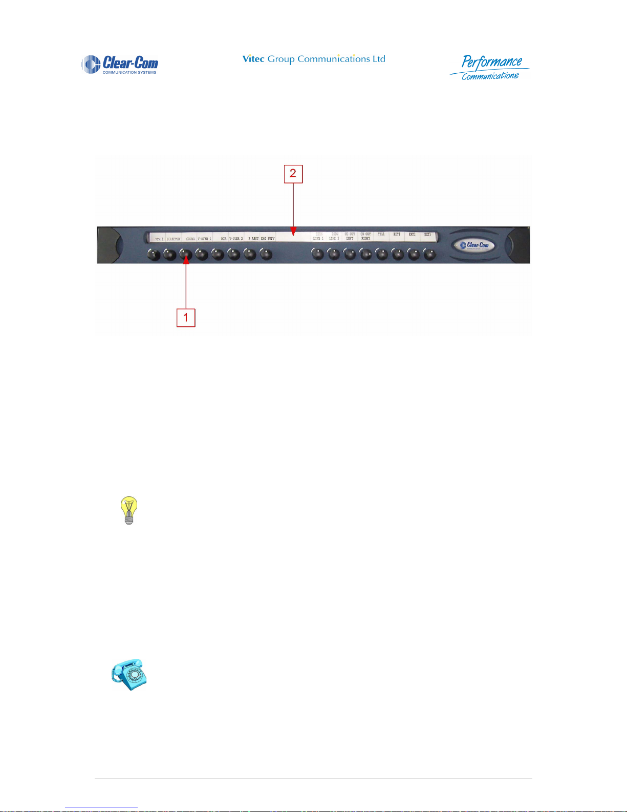
Panel User Guide Issue 1.4 4000 Digital Series II
Page 62 STA0380
4 Extension Panels
4.1 PD4203R-Level Control Panel (1RU)
Figure 20 - PD4203R Front View
4.1.1 Level Adjustment Control
The 4203 1RU Level Control Panel has sixteen Level Adjustment Controls. These controls are used to
vary the crosspoint level at the Control Panel for the assignments mad e to the selected DAKs. Turn the
level control clockwise to increase crosspoint gain, counter-clockwise to decrease gain.
There is a rotary switch inside the panel to set which bank of sixteen keys the level adjustment controls
are assigned to. Please refer to the installation guide for further details.
4.1.2 Designation Strip
Insert a paper Designation Strip to indicate the area of communication for each of the DAK's.
1 Level Adjustment Control 2 Designation Strip
Consult the Section PD4225 - Router Control Panel for Input / Output Level Control
description.
Designation strips can be printed using the CMAPSi/P Print facility.
Page 93

4000 Digital Series II Issue 1.4 Panel User Guide
STA0380 Page 63
4.2 PD4203 - Level Control Panel (1RU)
Figure 21 - PD4203 Front View
4.2.1 Level Adjustment Control
The 4203 1RU Level Control Panel has twenty Level Adjustment Controls. These controls are used to
vary the crosspoint level at the Control Panel for the assignments mad e to the selected DAKs. Turn the
level control clockwise to increase crosspoint gain, counter-clockwise to decrease gain.
There is a rotary switch inside the panel to set which bank of twenty keys the level adjustment controls
are assigned to. Please refer to the installation guide for further details.
4.2.2 Designation Strip
Insert a paper Designation Strip to indicate the area of communication for each of the DAK's.
1 Level Adjustment Control 2 Designation Strip
Consult the Section PD4225 - Router Control Panel for Input / Output Level Control
description.
Designation strips can be printed using the CMAPSi/P Print facility.
Page 94

Panel User Guide Issue 1.4 4000 Digital Series II
Page 64 STA0380
4.3 PD4206R - 16 Key Extension Panel (1RU)
Figure 22 - PD4206R Front View
4.3.1 Direct Access Key (DAK)
The 4206R Extension Panel has sixteen Direct Access Key (DAK) pushbuttons. These DAKs are used
to make Listen and/or Talk routes to and from the Control Panel or other audio connections. The DAK
can also be assigned to trigger a control event from either the Control Panel or the matrix.
There is a rotary switch inside the panel to select which bank of sixteen keys it controls in the range 33
- 112. For further details please refer to the installation manual.
The pushbutton operation is selectable from a range of options and set via the Configuration and Master
Assignment Programming System (CMAPSi) workstation software. The pushbutton actions include:
1 Indicator LED 3 Designation Strip
2 Direct Access Key (DAK)
Table 23: PD4206R DAK Operation
Latch When a DAK is pressed and released, it latches in the engag ed pos i-
tion. Pressing the DAK again disengages it.
Non-Latch When a DAK is pressed and held depressed, it automatically disen-
gages when released.
Latch/Non-Latch A combination of the two above such that a quick press will latch the
button and a slow press will be the non-latch action.
Dual Talk/Listen When a DAK is momentary pressed, it makes a latched Listen Route.
The DAK can then be pressed and held to make a Talk Route at the
same time, and released to unmake the Talk Route. A second momentary press disengages the DAK and the latched Listen Route.
Interlock Group A DAK can be assigned to any one of eight interlock groups A - H.
Within an interlock group only one DAK may be active at any one time.
If a DAK in a given group is pressed whilst another DAK in the same
group is already active the currently active key is deactivated and the
key pressed becomes active.
Page 95

4000 Digital Series II Issue 1.4 Panel User Guide
STA0380 Page 65
The Direct Access Keys can be programmed with a range of attributes as set in the Configuration and
Master Assignment Programming System (CMAPSi) workstation software. The pushbutton attributes
are:
NOTE: For the above functions, the destination can be a single or group of panels and external sources,
conferences or IFBs.
4.3.2 PD4206R Direct Access Key Indicator LED
The tri-coloured LEDs associated with the Direct Access Keys (DAKs) have the following meanings:
• Red (R) means “Talk” (key pressed).
• Green (G) means “Listen” (incoming audio from that source).
• Orange (O) means activity (a mix of Talk and Listen).
4.3.3 Designation Strip
Insert a paper Designation Strip to indicate the area of communication for each of the DAK's.
NOTE: Designation strips can be printed using the CMAPSi Print facility.
Table 24: PD4206R Pushbutton Attributes
Talk Only A single DAK pr ess ca uses an a udio ro ute to be mad e from the sour ce
panel to the desired destinations. Normally used for communication
from one panel to another.
Listen Only A single DAK press causes an audio route to be made from the desti-
nation. Used when listening to an external audio signal (not originating
from a Control Panel) is required.
Talk and Listen A single DAK press causes a bi-directional audio route to be made
between the source panel and the destinations. Used between panels
and also with certain external audio signals.
Talk & Forced Listen This is similar to Talk and Listen except that the Listen route is perma-
nently made. The operator need only press the DAK to talk.
Page 96

Panel User Guide Issue 1.4 4000 Digital Series II
Page 66 STA0380
4.4 PD4206 - 20 Key Extension Panel (1RU)
Figure 23 - PD4206 Front View
4.4.1 Direct Access Key (DAK)
The 4206 Extension Panel has twenty Direct Access Key (DAK) pushbuttons. These DAKs are used to
make Listen and/or Talk routes to and from the Co ntrol Panel or other aud io conne ctions. T he DAK can
also be assigned to trigger a control event from either the Control Panel or the matrix.
There is a rotary switch inside the panel to select which bank of twenty keys it controls in the range 33 -
112. For further details please refer to the installation manual.
The pushbutton operation is selectable from a range of options and set via the Configuration and Master
Assignment Programming System (CMAPSi) workstation software. The pushbutton actions include:
1 Direct Access Key (DAK) 3 Listen Tally LED
2 Talk Tally LED 4 Designation Strip
Table 25: PD4206 DAK Operation
Latch When a DAK is pressed and released, it latches in the engag ed pos i-
tion. Pressing the DAK again disengages it.
Non-Latch When a DAK is pressed and held depressed, it automatically disen-
gages when released.
Latch/Non-Latch A combination of the two above such that a quick press will latch the
button and a slow press will be the non-latch action.
Dual Talk/Listen When a DAK is momentary pressed, it makes a latched Listen Route.
The DAK can then be pressed and held to make a Talk Route at the
same time, and released to unmake the Talk Route. A second momentary press disengages the DAK and the latched Listen Route.
Interlock Group A DAK can be assigned to any one of eight interlock groups A - H.
Within an interlock group only one DAK may be active at any one time.
If a DAK in a given group is pressed whilst another DAK in the same
group is already active the currently active key is deactivated and the
key pressed becomes active.
Page 97

4000 Digital Series II Issue 1.4 Panel User Guide
STA0380 Page 67
The Direct Access Keys can be programmed with a range of attributes as set in the Configuration and
Master Assignment Programming System (CMAPSi) workstation software. The pushbutton attributes
are:
NOTE: For the above functions, the destination can be a single or group of panels and external sources,
conferencers or IFBs.
4.4.2 Talk Tally LED
This Red LED indicates that the button action is active (either latched or transient), dependent on
individual programming/assignment This LED will flash when the destination is busy if this feature is
enabled.
4.4.3 Listen Tally LED
This Green LED indicates that an audio is being received by the Control Panel from the source
associated with the DAK.
4.4.4 PD4206 Direct Access Key Indicator LED
The coloured LEDs associated with the Direct Access Keys (DAKs) have the following meanings:
• Red (R) means “Talk” (key pressed).
• Green (G) means “Listen” (incoming audio from that source).
• Orange (O) means activity (a mix of Talk and Listen).
4.4.5 Designation Strip
Insert a paper Designation Strip to indicate the area of communication for each of the DAK's.
NOTE: Designation strips can be printed using the CMAPSi Print facility.
Table 26: PD4206 Pushbutton Attributes
Talk Only A single DAK pr ess ca uses an a udio ro ute to be mad e from the sour ce
panel to the desired destinations. Normally used for communication
from one panel to another.
Listen Only A single DAK press causes an audio route to be made from the desti-
nation. Used when listening to an external audio signal (not originating
from a Control Panel) is required.
Talk and Listen A single DAK press causes a bi-directional audio route to be made
between the source panel and the destinations. Used between panels
and also with certain external audio signals.
Talk & Forced Listen This is similar to Talk and Listen except that the Listen route is perma-
nently made. The operator need only press the DAK to talk.
Page 98

Panel User Guide Issue 1.4 4000 Digital Series II
Page 68 STA0380
4.5 PD4211 LCD Key Panel (1RU)
Figure 24 - PD4211 Front View
NOTE: Microphone is shown here for illustrative purposes only. Contact Vitec Group Communications
for details of suitable products.
4.5.1 Microphone Socket
Insert the optional microphone into this socket. The detachable microphone is connected via a 3-pin
screw locking DIN connector.
4.5.2 Crosspoint Level Control
Press the pot switch above the Reply Key to activate Cross-point Level Control Mode. The red LED
associated with the controller is illuminated while Level Control Mode is active.
1 Microphone Socket 7 Soft Pushbutton
2 Crosspoint Level Control 8 Auxiliary Volume Control
3 Shift Pushbutton 9 Main Volume Control
4 Microphone Mute Pushbutton 10 Reply Key
5 Loudspeaker 11 Direct Access Key (DAK)
6 Headset Select Pushbutton 12 Headset Socket
Consult the Vitec Group Communications Installation Guide for further details.
Contact Vitec Group Communications for suitable Microphone
options.
Vitec Group Communications can offer three different types type of
microphones - 100mm, 340mm and 490mm goosenecks.
All panels are available with DIN 5 headset connection.
1
6
2 3 4 5
10 9 8
1112 7
Page 99

4000 Digital Series II Issue 1.4 Panel User Guide
STA0380 Page 69
Selecting a DAK, while turning the controller clockwise or counter-clockwise, causes the cro ss-point
level to increase or decrease, respectively. The cross-point level indicator and a numeric indication of
the level setting is displayed while the DAK is pressed.
Only one DAK press is recognised at a time for cross-point level control. Further DAK presses are
ignored until the first DAK is released.
After 20 seconds without any DAK or pot activity the panel automatically exits Level Control Mode and
reverts to normal intercom mode.
4.5.3 Shift Pushbutton
The Shift pushbutton toggles between the Main Page and the additional DAK assignments of the Shift
Page. The red LED will flash when a call is detected for an assignment on the page not currently
displayed. When that page is accessed, the LED will illuminate.
NOTE: SOFT Mode can be entered when the Shift Page is selected, allowing local assignment of the
Shift Page DAKs. However, the Shift Page MUST be selected before SOFT Mode is entered a s the Shift
pushbutton is only functional in normal intercom mode.
4.5.4 Microphone Mute Pushbutton
Press the Microphone Mute Pushbutton to mute the active microphone. The red LED is illuminated whilst
the microphone is muted. Another press will re-enable the microphone.
4.5.5 Loudspeaker
Audio is output from the loudspeaker unless the Headset Select is engaged.
4.5.6 Headset Select Pushbutton
The Headset Select Pushbutton is used to select headset operation. The red LED is illuminated to
indicate that the headset microphone is active and the detachable microphone and loudspeaker are
muted.
Contact Vitec Group Communications for suitable External Loudspeaker options
Your panel loudspeaker reduces volume automatically when a talk key
is pressed. This is to help reduce the chance of howlround (audio
feedback) occurring.
Page 100

Panel User Guide Issue 1.4 4000 Digital Series II
Page 70 STA0380
4.5.7 Soft Pushbutton
Press the pushbutton to enable the Control Panel Soft Mode operation. The red LED is illuminated.
Another press will return the Control Panel to normal operation.
4.5.8 Auxiliary Volume Control
Turn the Auxiliary Volume Control clockwise to increase the auxiliary channel volume, or anti-clockwise
to decrease the volume. The auxiliary channel is not always used.
The current setting of either the Main or Auxiliary Volume Control is displayed as a level bar on the Reply
Key, above the Reply Key text. Turning these controls clockwise or counter-clockwise, increases or
decreases the length of the relevant control bar.
The most recently moved control is displayed. If the Auxiliary Volume level setting is displayed and the
Auxiliary Volume Control is static for 2 seconds, the display reverts to showing the Main Volume level
setting. (The auxiliary level bar is displayed as a broken line to distinguish it from the main level bar).
The level bars are graded in 0.5 steps from a minimum setting of 0.0 (off) to a maximum setting of 10.0
(approximately +12 dB). Each 0.5 step corresponds to 1 pixel of the level bar. The default setting for both
controls is 5.0 (approximately 0 dB).
Pressing and holding the auxiliary control pot switch shows the current level setting for each DAK. There
is no LED indication for this switch action.
4.5.9 Main Volume Control
Turn the Main Volume Control clockwise to increase the intercom volume, anti-clockwise to decrease
the volume.
The current setting of either the Main or Auxiliary Volume Control is displayed as a level bar on the Reply
Key, above the Reply Key text. Turning these controls clockwise or counter-clockwise, increases or
decreases the length of the relevant control bar.
The most recently moved control is displayed. If the Auxiliary Volume level setting is displayed and the
Auxiliary Volume Control is static for 2 seconds, the display reverts to showing the Main Volume level
setting. (The auxiliary level bar is displayed as a broken line to distinguish it from the main level bar).
Consult the Section “LCD Key Panel Soft Mode” for Soft Mode programming description.
A panel fitted with a PDE4537 options card can have an external line
level auxiliary input.
Auxiliary level indicator
R E P L Y
 Loading...