

Page 1
5
ENGLISH
INST ALLING THE PROJECTOR
1
• Unpacking
Open the wooden box, unscrew the two
transport screws (1), remove the projector from the packing and place it on
a flat horizontal surface.
Unpack the standard accessories supplied with the fixture.
Inspect the lamp change label (2) and
replace it with one of the optional language versions if necessary.
Make certain that the lamp change
label is never removed, as it displays
important safety information.
POWER SUPPLY AND INTERFACE
2
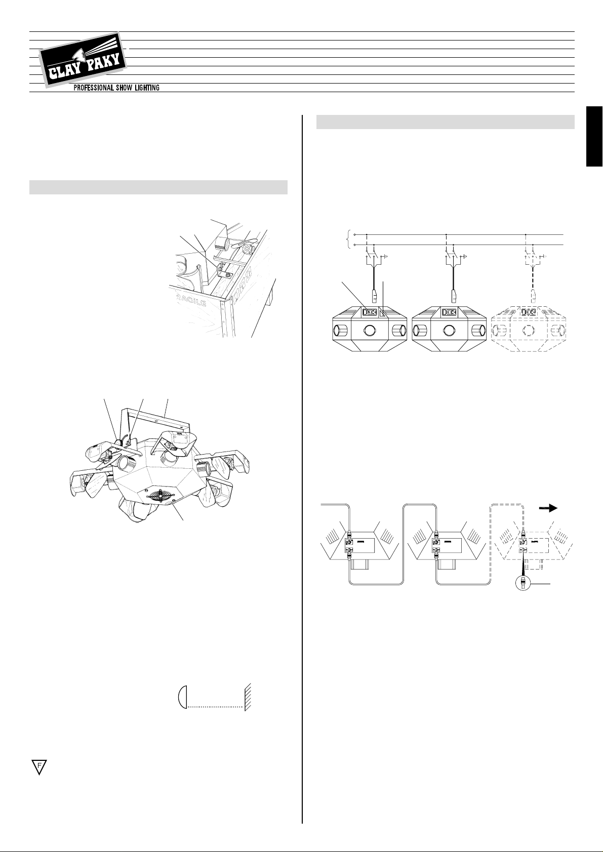
• Connecting to the electrical power supply
The operations described in this heading must be carried out by a licensed electrician.
The projector must be wired up to the electrical power supply using the special
socket connector provided. It is good policy to connect projectors to the power
supply by way of dedicated switches, so that each can be turned on and off individually from a remote station.
The projector is designed to operate at the voltage and frequency indicated on the
electrical data plate (6) affixed to the rear end.
Check that these two values correspond to the mains voltage and frequency.
IMPORTANT: the projector must be connected to a power supply circuit
having a proper earth system (Class I appliance).
• Connecting the control signals: RS 232/423(PMX) - DMX 512
Projectors are wired up to the controller and one to the next using two-core
screened cable and Cannon 5 pin XLR type plug/socket connectors.
To connect a DMX line, a ter minating plug (7) with a 100 Ω resistor wired between
pins 2 and 3 must be fitted to the last projector connected in series; the plug is not
required when using an RS232/423(PMX) signal.
The wires must not come into contact with each other or with the metal casing of the plug.
The casing of the plug/socket must be connected to the screen and to pin 1
of the connectors.
Having completed the operations described above, press the on/off switch (8).
Check that the lamp comes on and that the auto-reset sequence starts.
• Initial assembly operations
Fix the bracket (3) with the screws (4) and secure it by tightening the knobs (5).
1
543
2
• Fitting the lamp
Refer to the directions for replacement of the lamp given under heading 5 MAINTENANCE.
• Installing the projector
The projector can be mounted in any position without its operating characteristics
being affected.
IMPORTANT: fix the projector in the desired position utilizing the holes in the
bracket. Secure preferably using two ø 12 mm bolts complete with nuts and lock
washers.
Make certain that the anchorage is stable before positioning the projector.
• Minimum distance from target objects
The projector must be positioned in such a
way that objects struck by the beam are
separated from the lens by a distance of at
least 0.5 m. (1’ 8”)
• Minimum distance of inflammable objects from any part of the equipment:
70 mm. (3’)
The fixture may be mounted on surfaces rated normally inflammable.
IMPORTANT: For better and more reliable operation of the projector, the ambient
temperature must not exceed 35° C (95° F). Protection factor IP 20: the fixture is
protected against penetration of solid bodies more than 12 mm (0.5”) in diameter
(first digit 2), but can be damaged by spray, jet, drip or rain water (second digit 0).
8
7
6
Mains
IMPORTANT: Read carefully. It is essential for the correct and safe use of the
equipment that erectors and operators should be fully conversant with the information and instructions given in this manual.
INSTRUCTION MANUAL
TORNADO
ENGLISH
HMI 575
®
L
N
(
1’ 8”
0.5 m
)
HMI 575
Page 2
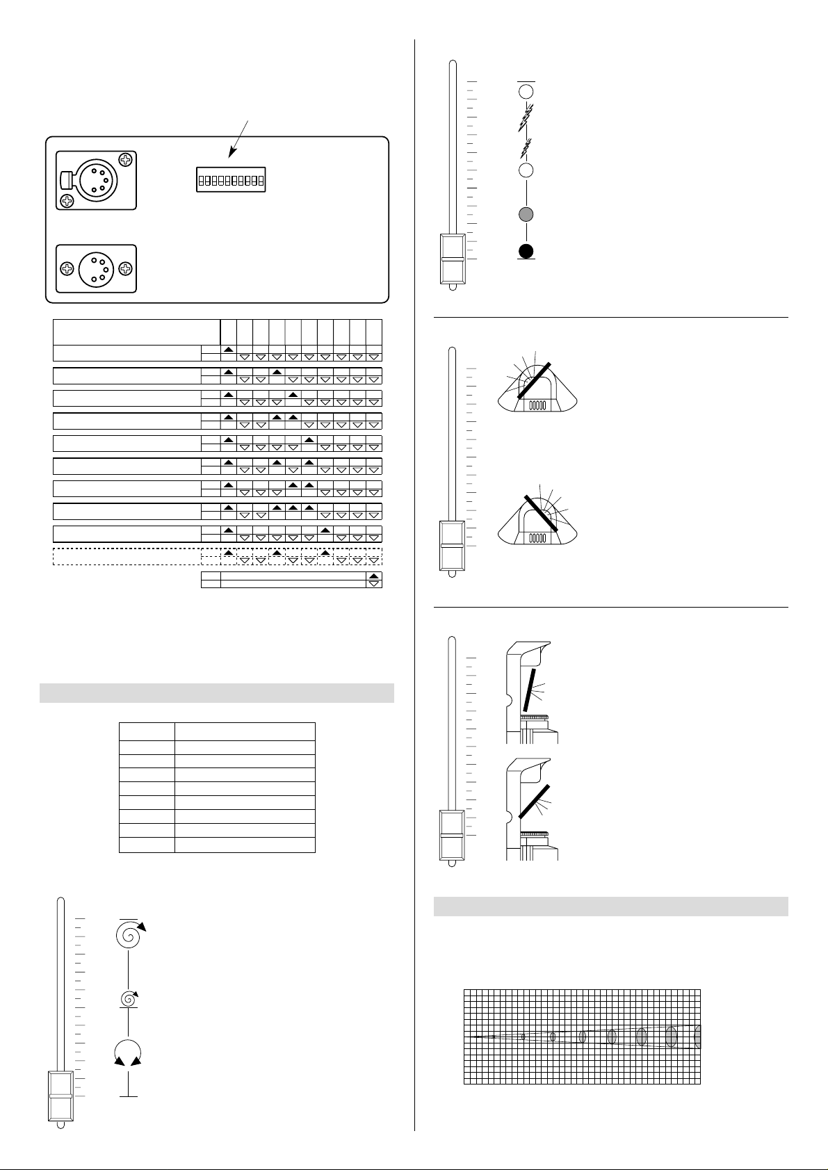
• Projector address codes
Each TORNADO projector uses 8 control channels.To ensure that different projectors are addressed correctly by the controller, a code must be assigned to each one .
This operation is carried out on each TORNADO by setting the microswitches as
indicated in the table below.
Setting the TEST switch to the ON position for a few seconds with the projector
powered-up, an auto-reset routine is carried out.Leaving the TEST switch at the ON
position for a longer period, a full self-test program will be completed; once the
operation has terminated, return the switch to the OFF position.
CHANNEL FUNCTIONS
3
CHANNEL FUNCTION
1
2
3
4
5
6
7
8
COLOUR CHANGE
DIMMER/STOPPER/STROBE
PAN (mirrors 1 & 4)
TILT (mirrors 1 & 4)
PAN (mirrors 2 & 5)
TILT (mirrors 2 & 5)
PAN (mirrors 3 & 6)
TILT (mirrors 3 & 6)
In the 0% to 50% range of adjustment, the change of colour in
response to movement of the potentiometer is linear and continuous.
From 50% to 100% the wheel rotates
continuously at increasingly high
speed.
In the 0% to 50% range of adjustment the dimmer opens gradually to
maximum aperture.
Strobe effect is produced from
54.7% to 95% with frequency
increasing from 1 flash/1.5 seconds
to 5 flashes/second.
The aperture remains fixed from
95% to 100%.
Horizontal movement of the mirrors
(Pan) is linear and continuous in
response to the movement of the slider from the zero position to the opposite limit of excursion.
The mirrors can be stopped at any
intermediate position.
0
1
2
3
4
5
6
7
8
9
10
• COLOUR CHANGE channel 1
• DIMMER / STOPPER / STROBE - channel 2
• PAN - channel 3 (5) (7)
Vertical movement (Tilt) of the mirrors
is linear and continuous in response
to movement of the slider from the
zero position to the opposite limit of
excursion.
The mirrors can be stopped at any
intermediate position.
• TILT - channel 4 (6) (8)
LENS UNITS
4
BEAM OPENING m
115.2
28.8 13 7.25
4.65
3.25 1.86 1.11
(lux)
0
010203040
DISTANCE m
5152535
1
2
1
2
0” 1’ 1”9” 1’ 5” 1’ 10” 2’ 2” 2’ 6” 2’ 11” 3’ 3”
DIAMETER ft in
0 0,33 0,55 0,77 0,99
DIAMETER m
0,22 0,44 0,66 0,88
0” 32’ 10”
DISTANCE ft in
16’ 5” 49’ 3” 65’ 7” 82’
98’ 5” 114’ 10” 131’ 3”
HMI 575
1240
310 140 78
50
35 20 12
(fc)
GRAPHS SHOWING BEAM DATA AND ILLUMINATION VALUES
Beam angle ( 1,9°)
Spotlight selection
6
TEST
256
1
ON
128643216842
DIP
10987654321
10
9
8
7
6
5
4
3
2
1
0
1
2
4
8
CODE
1
2
Projector - Channels 9-16
1-8Projector - Channels
17-24Projector - Channels3
25-32Projector - Channels4
33-40Projector - Channels5
41-48Projector - Channels6
49-56Projector - Channels7
57-64Projector - Channels8
65-72Projector - Channels9
73-80Projector - Channels10
OFF
OFF
OFF
OFF
OFF
OFF
OFF
OFF
OFF
OFF
OFF
ON
ON
ON
ON
ON
ON
ON
ON
ON
ON
ON
163264
128
256
TEST
10
9
8
7
6
5
4
3
2
1
0
10
9
8
7
6
5
4
3
2
1
0
Page 3

7
TECHNICAL DATA
CONSTRUCTION FEATURES
Safety devices
•
Power supply shuts off automatically in the event of overheating or
cooling system failure.
•
Power shuts off automatically when
cover is opened.
Cooling
Forced ventilation cooling system
using axial flow fans.
Housing
In steel sheet with epoxy powder coated finish.
Mounting
•
Steel bracket with epoxy powder
coated finish.
•
Bracket adjustable through 95°.
Operating position
Will function in any position.
Weights and dimensions
Weight: 35 kg (77 lbs)
ELECTRICAL / MECHANICAL
SPECIFICATIONS
Power supply
•
220 - 240V 50Hz
•
200 - 220V 60Hz
Lamp
Metal halide type with special built-in
power supply unit.
•
Type HMI 575W
•
- Cap SFc 10-4
•
- Colour temperature 6000 K
•
- Luminous flux 49000 lm
•
- Average life 750 h
Power consumption
1500 VA at 230V 50Hz
Motors
N. 14 microstepping motors with full
microprocessor control.
CONTROL SYSTEMS
Channels
N. 8 control channels.
Inputs
TORNADO is set up to accept digital
control signals from controllers or
computers.
•
Digital serial input
RS232/423(PMX) or DMX 512
MIRROR HEADS
•
In diecast aluminium with epoxy
powder coating.
•
Very high luminous efficiency
mirrors.
Movement
•
Produced by two microprocessor
controlled microstepping motors.
•
Infinitely variable speed of rotation;
maximum values:
- PAN = 0.4 sec (150°)
- TILT = 0.3 sec (110°)
•
Continuous and uniform movement.
Resolution:
- PAN = ±0.3° (150°)
- TIL T = ±0.2° (110°)
7
ENGLISH
IMPORTANT: do not use solvents or
alcohol
Parts that need cleaning frequently
Parts that need cleaning monthly
Internal components should be
cleaned once a year by dislodging
dust and dirt with a brush and removing it simultaneously with a vacuum
cleaner.
IMPORTANT: isolate the projector from the electrical power supply before commencing maintenance work of any description.
The maximum temperature on the outer surface of the projector under normal
operating conditions is 80° C (176° F).
After switching off, do not remove any part of the projector for at least 7 minutes,
as indicated on the lamp change label (2).
Once this time has elapsed, the risk of a lamp exploding is practically zero.
If the lamp needs changing, wait a further 15 minutes to avoid the risk of burns.
In the event of a lamp exploding, the projector is designed to prevent fragments of
glass from being scattered. The lenses supplied with the projector must be fitted
at all times, and if visibly damaged, must be replaced with genuine spares.
• Changing the lamp
Unscrew the two knobs (9) and
remove the lamp change cover (10).
Loosen the nut (11) of the lamp to be
replaced and remove it from plate
(12) gripping it by attachment (13).
Remove the new lamp from its box,
remove the nut (14) and loosen the
other nut (11).
Screw the lamp directly into plate
(12) gripping it by attachment (13).
Fit metal strip (15) onto attachment
(16) and fully tighten nut (11).
Refit cover (10) tightening knobs (9)
fully.
CAUTION: The projector uses a high pressure lamp with external starter.
- When fitting a new lamp, read the manufacturer's instructions carefully.
- The lamp must always be changed without delay if damaged or deformed b y
heat.
• Replacing fuses
To replace the fuses, press the tab
(18) and pull out the fuse holder
(19). Replace any blown fuse with
one of the same type and rating as
indicated on the label (20) attached
to the holder (19).
Insert the fuse holder and push in to
engage the tab (18).
IMPORTANT: for uniform distribution of the light beam, the lamp must be positioned so that the glass pip (17) on the bulb does not coincide with any of the six
optical axes of the projector.
MAINTENANCE
5
910
11
14 13
17
11
16
15
17
16
12
13
20 19 18
TROUBLESHOOTING
6
No electrical power supply. Check that the power supply is
available at the mains socket
and/or that the fuses are intact.
THE PROJECTOR DOES NOT LIGHT UP
ANOMALIES
ELECTRONICS NOT WORKING
PROJECTION FAULTY FAULTS
REDUCED BRIGHTNESS
POSSIBLE CAUSES
CHECKS AND REMEDIES
•
•
•
•
•
•
•
•
•
Lamp expended or faulty. Change lamp (see instructions).
Signal transmission cable shortcircuiting or disconnected.
Change cables.
Address codes incorrect. See projector coding instr uctions.
Defect in electronic circuits. Contact an authorized technician.
Lenses broken. Contact an authorized technician.
Deposit of dust or grease. Clean (see instructions).
• Routine cleaning
To maintain the light output of the projector undiminished, parts that tend to
accumulate dust and grease must be cleaned periodically.
The projector will give long and trouble-free service if these simple guidelines are
followed.
To remove dirt from the lenses and filters, use a soft cloth moistened with any
liquid detergent suitable for cleaning glass.
(39.4”)
1.000
(19.7”)
500
FUSE
5 x 20
10 A
250 V
Page 4

WIRING DIAGRAM
8
The products referred to in this manual comply with EC
Directives on:
• Low Voltage 73/23
• Electromagnetic Compatibility 89/336
The specifications published in this manual are not binding, and may be revised or updated
at any time by Clay Paky without notice in the interests of improving product quality.
8
 Loading...