

Page 1
7
IMPORTANT: the safety wire must be secured to the projector and to the supporting
structure in such a way that if the bracket should fail, the projector will fall as short a
distance as possible. Following any such failure, the safety wire must be replaced
with a genuine Clay Paky spare.
•
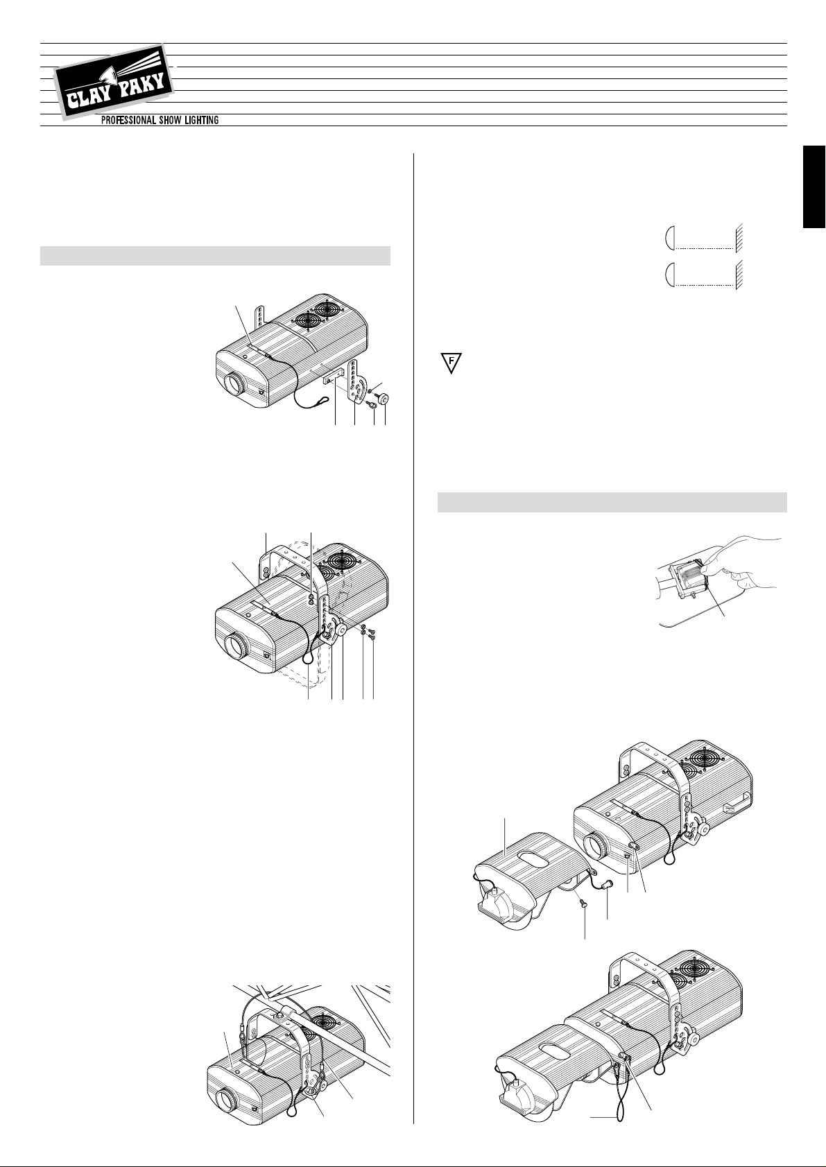
Minimum distance from target objects
The projector must be positioned in such a way
that objects struck by the beam are separated from
the lens at least by the distance indicated on the
lamp change label against the symbol shown
alongside.
•
Minimum distance of inflammable materials from any part of the equipment:
0.10 m (4”) for HMI 1200, 0.07 m (3”) for HMI 575.
The projector may be mounted on surfaces rated normally inflammable.
IMPORTANT: For better and more reliable operation of the projector, the ambient
temperature must not exceed 35° C (95° F). Protection factor IP 20: the appliance
is protected against penetration of solid bodies more than 12mm (0.5”) in diameter
(first digit 2), but can be damaged by spray, jet, drip or rain water (second digit 0).
Fasten the safety wire (11) of lamp change cover (12) to graduated plate (3).
•
Fitting the lamp
Refer to directions for replacement of the lamp given under heading 7 MAINTENANCE.
•
Installing the projector
The projector can be mounted in any position without its operating characteristics
being affected.
IMPORTANT: fix the projector in the desired position utilizing the holes in the bracket (7). Secure preferably using two ø12 bolts with nuts and lock washers.
Make certain that the anchorage
is stable before positioning the
projector.
•
Fitting the safety wire
A safety wire (15) is supplied for
use with the HMI 1200 version.The
wire must be secured to the gantry
or other structure and then
anchored to the eyebolts (4) on the
projector itself.
•
Initial assembly operations
Position block (2) on the projector
body so that it is aligned with the
threaded holes; secure graduated
plate (3) with eyebolt (4) and then fit
knob (5) and washer (6).
Position bracket (7) on graduated
plate (3) at the desired height; inser t
bushing (8), chamfered washer (9)
and screw (10) in the selected hole
and tighten using the supplied Allen
key.
The bracket (7) can also be fitted on
the underside of the projector by
inverting the position of graduated
plate (3).
If the projector has been shipped
with plate (3) already fitted, before
removing the plate (if necessary)
remove the safety bolt located inside
the fixture in correspondence with
eyebolt (4).
Set the projector support in the
desired position and secure by tightening knobs (5).
TIGER SCAN
ENGLISH
HMI 575
HMI 1200
•
Unpacking
Open the box, remove the projector
from the packing and place it on a flat,
horizontal surface.
Unpack the standard accessories
supplied with the equipment. Inspect
the lamp change label (1) and replace
it with one of the optional language
versions if necessary.
Make certain that the label is never
removed, as it displays important
safety information.
•
Unpacking
Open the box, take out the mirror head, position it on a horizontal surface and remove the
elastic transit bands (16) from the tilt motor.
•
Fitting the mirror head
Fit the mirror head (17) to the projector and secure with the three knobs (18).
Connect the mirror head plug (19) to the socket (20) located on the front of the
projector.
Connect the metal safety wire (21) to the tag (22) on the projector.
INSTALLING THE MIRROR HEAD
2
6
5432
1
4
15
12
16
2220
19
18
17
2221
ENGLISH
INST ALLING THE PROJECTOR
1
IMPORTANT: Read carefully. It is essential for the correct and safe use of the
equipment that erectors and operators should be fully conversant with the
information and instructions given in this manual.
INSTRUCTION MANUAL
12
78
10911 3
5
®
(5’ 11”)
1.8 m
(8’ 2”)
2.5 m
HMI 575
HMI 1200
Page 2
8
RS 232/423
DMX 512
0.00
10
0.00
10
0.00
1 0
The projector is designed to operate at the voltage and frequency indicated on the
electrical data plate (23) affixed to the rear end.
Check that these two values correspond to the mains voltage and frequency.
IMPORTANT: the projector must be connected to a power supply circuit having
a proper earth system (Class I appliance).
•
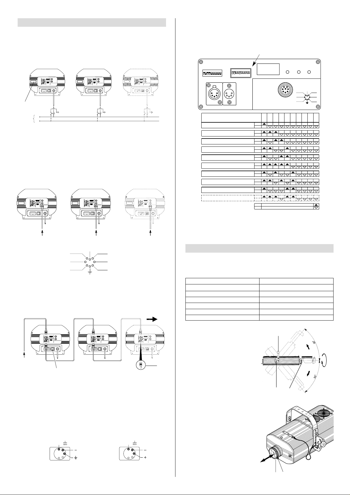
Connecting the control signals
0-10V CONNECTION
The connection between controller and projector must be made using a multicore
cable with 8 wires of 0.25mm
2
section and a DIN 8 PIN 45° plug/socket connector.
RS 232/423(PMX) - DMX 512 CONNECTION
Projectors are wired up to the controller and one to the next using two-core
screened cable and Cannon 5 pin XLR type plug/socket connectors.
To connect a DMX line, a terminating plug (24) with a 100Ω resistor wired between
pins 2 and 3 must be fitted to the last projector connected in series; the plug is not
required when using an RS232/423(PMX) signal.
The wires must not come into contact with each other or with the metal casing
of the plug.
The casing of the plug/socket must be connected to the screen and to pin 1
of the connectors.
Having completed the operations described above, press the on/off switch (25).
Check that the lamp comes on and that the auto-reset sequence starts.
0 - 10V0 - 10V 0 - 10V
0.00
10
0.00
10
0.00
1 0
COL 2
1 GOBO
3 GOBO
Is
6 TILT
STOP 4
5 PAN
ROTATE
CHANGE
18-25 VDC
25
24
SIGNAL
SCREEN
SIGNAL
54
3
2
1
RS232/423
(PMX)
SIGNAL
SCREEN
SIGNAL
54
3
2
1
DMX
512
N
L
Mains
0.00
10
0.00
10
0.00
1 0
•
Connecting to the electrical power supply
The operations described in this heading must be carried out by a licensed
electrician.
It is good policy to connect projectors to the power supply by wa y of dedicated s witches, so that each can be turned on and off individually from a remote station.
POWER SUPPLY AND INTERFACE
3
•
Alignment procedure
Before positioning the projector, set the channels as shown in the following table:
POSITIONING THE PROJECTOR
4
Setting the TEST switch to the ON position for a few seconds with the projector powered-up, an auto-reset routine is carried out.Leaving the TEST switch at the ON position for a longer period, a full self-test program will be completed;once the operation
has terminated, return the switch to the OFF position.
CHANNEL
SLIDER POSITION
1 GOBO ROTATION
2 COLOUR WHEEL
3 GOBO SELECTION
4 DIMMER/STOPPER/STROBE
5PAN
6 TILT
-
-
-
100 % (white beam
)
50%
50%
After setting up the channels loosen
the knobs (5), and manoeuvre the projector on its bracket (7) until the beam
is directed at the centre of the scene,
then retighten the knobs (5).
•
Adjusting the mirror head
The beam can be positioned not only
by moving the entire projector, b ut also
by adjusting the mirror head.
To do this, loosen the three knobs
(18), turn the mirror head to the
desired position, and retighten the
knobs.
•
Adjusting the lens
Move the lens (26) back and forward
until the projected image is satisfactorily focused, then tighten the knob
(27).
7
518
180°
26 27
•
Projector address codes (for digital signals)
Each TIGER SCAN projector uses 6 control channels.To ensure that different projectors are addressed correctly by the controller, a code must be assigned to each
one.This operation is carr ied out on each TIGER SCAN by setting the microswitches as indicated in the table below.
23
Projector
1
- Channels
1-6
124
8
163264
128
256
TEST
OFF
ON
CODE
Projector
9
- Channels
49-54
ON
OFF
Projector
8
- Channels
43-48
ON
OFF
Projector
10
- Channels
55-60
ON
OFF
OFF
ON
Projector
7
- Channels
37-42
ON
OFF
Projector
6
- Channels
31-36
ON
OFF
Projector
5
- Channels
25-30
ON
OFF
Projector
4
- Channels
19-24
ON
OFF
Projector
3
- Channels
13-18
ON
OFF
Projector
2
- Channels
7-12
OFF
ON
019
DIGITAL START ADDRESS SELECT
ANALOGUE INPUTS
0-10V
DIGITAL INPUT LEDS
148
124816
1283264
TEST
256
ON
12 436578109
DIGITAL INPUT
RECEIVING
PMX
RECEIVING
DMX
DATA
ERROR
COL 2
1 GOBO
3 GOBO
Is
6 TILT
STOP 4
5 PAN
ROTAT E
CHANGE
18-25 VDC
Spotlight selection
Page 3

9
CHANNEL FUNCTIONS
5
CANNEL
FUNCTION
1
GOBO ROTATION
2 COLOUR WHEEL
3 GOBO SELECTION
4 DIMMER/STOPPER/STROBE
5PAN
6
TILT
2
0
1
3
4
5
6
8
9
10
7
• TILT - channel 6
0
1
2
3
4
5
6
7
8
9
10
White
1
2
3
4
• GOBO SELECTION - channel 3
0
1
2
3
4
5
6
7
8
9
10
100%
75%
50%
0%
STOP
540°
360°
0°
From 0% to 49.7% the gobo rotates
through 540° (1
1/2 turns).
From 50% to 75% the gobo rotates
more quickly at first and then slows
down to a complete stop.
From 75.5% to 100% the gobo begins
turning in the opposite direction, slowly at first and then gradually faster.
The change occurs instantaneously as
the slider reaches different preset levels on the graduated scale.
Vertical movement (Tilt) of the mirror
occurs gradually as the slider is
advanced. From the zero position mirror movement is linear and continuous
up to the opposite end of travel. The
mirror can be stopped at any intermediate angle.
• GOBO ROTATION - channel 1
• COLOUR WHEEL - channel 2
In the 0% to 50% range of adjustment
the colour change in response to
movement of the potentiometer is linear and continuous so that the slider
can be stopped in intermediate positions to obtain a two-colour beam.
From 50% to 100% the wheel rotates
continuously with speed increasing
steadily from 0 to 300 rpm.
0
1
3
5
6
7
8
9
10
4
2
• DIMMER/STOPPER/STROBE - channel 4
In the 0% to 50% range of adjustment,
the dimmer opens gradually to maximum aperture.
Strobe effect is produced from 54.7%
to 95%, with frequency increasing
from 1 to 7 flashes/second.
The aperture remains fixed between
95% and 100% of the range.
6
8
10
0
1
2
3
4
5
7
9
Horizontal movement (Pan) of the mirror occurs gradually as the slider is
advanced. From the zero position mirror movement is linear and continuous
up to the opposite end of travel. The
mirror can be stopped at any intermediate angle.
• PAN - channel 5
ENGLISH
10
9
8
7
6
PINK
5
BLUE
4
ORANGE
3
GREEN
VIOLET
2
YELLOW
1
RED
WHITE
0
Page 4

10
34
LENS UNITS
6
7
6
5
4
3
2
1
0
1
2
3
4
5
6
7
BEAM OPENING m
0 5 10 15 20 25 30 35 40 DISTANCE m
0” 16’ 5” DISTANCE ft in
19.800
Standard Objective 1:2,5 / 250
4.950 2.200 1.237 792 550 404 309
13°
0 1,16 2,32 3,48 4,64 5,80 6,96 8,12 9,28 DIAMETER m
32’ 10” 49’ 3” 65’ 7” 82’ 98’ 5” 114’ 10” 131’ 3”
0” 3’ 10” DIAMETER ft in7’ 7” 11’ 5” 15’ 3” 19’ 22’ 10” 26’ 8” 30’ 5”
HMI 1200
1,839 460 204 115 73.6 51.1 37.5 28.7
fc
lux
HMI 575
762 190 84.6 47.6 30.5 21.1 15.5 11.9 fc
8.200 2.050 911 512 328 227 167 128 lux
7
6
5
4
3
2
1
0
1
2
3
4
5
6
7
BEAM OPENING m
0 5 10 15 20 25 30 35 40 DISTANCE m
0 1,95 3,9 5,85 7,8 9,75 11,7 13,65 15,6 DIAMETER m
4.000 1.000 444 250 160 111 81 62
Objective 1:3 / 150 wideangle
0” 16’ 5” DISTANCE ft in32’ 10” 49’ 3” 65’ 7” 82’ 98’ 5” 114’ 10” 131’ 3”
0” 6’ 5” DIAMETER ft in12’ 10” 19’ 2” 25’ 7” 32’ 38’ 5” 44’ 9” 51’ 2”
22°
HMI 1200
372 92.9 41.2 23.1 14.9 10.3 7.52 5.76
lux
fc
2.800 700 311 175 112 78 57 44 lux
HMI 575
260 65 28.9 16.3 10.4 7.25 5.3 4.09 fc
GRAPHS SHOWING BEAM DATA AND ILLUMINATION VALUES
IMPORTANT: isolate the projector from the electrical power supply before commencing maintenance work of any description. The maximum temperature on the
outer surface of the projector under normal operating conditions is shown on the
lamp change label. After switching off, do not remove any part of the projector for
the time indicated on the lamp change label (1).
Once this time has elapsed, the risk of a lamp exploding is practically zero.If the
lamp needs changing, wait a further 20 minutes to avoid the risk of burns. In the
event of a lamp exploding, the appliance is designed to prevent fragments of glass
from being scattered. The lenses supplied with the appliance must be fitted at all
times, and if visibly damaged, must be replaced with genuine spares.
MAINTENANCE
7
•
Opening the projector
Loosen the knob (28) and remove the
lamp access cover (12).
Once the necessary work has been
completed, refit the cover (12) and
tighten the knob (28).
•
Changing the lamp
Open the projector, loosen the two side nuts (29) of the lamp to be changed and
remove it from the supports (30).
Remove the new lamp from its bo x, loosen the two side nuts (29) and locate the lamp
in the supports (30). Finally, retighten the nuts.
28
30
29
31 29
121
IMPORTANT: for uniform distribution of the light beam, the lamp must be positioned so that the glass pip (31) on the bulb does not coincide with the optical axis
of the projector.With this in mind, locate the pip as high up as possible.
CAUTION: The projector uses a high pressure discharge lamp with
external starter.
- When fitting a new lamp, read the manufacturer’s instructions carefully.
- The lamp must always be changed without delay if damaged or deformed by heat.
•
Changing the colour filters
Having opened the projector, identify
the filter to be changed, grip firmly
between thumb and forefinger and
push against the spring clip (32) until
free of the fixed clips (33).
Bend the filter outwards and remove.
Offer the new filter to the spring clip
(32) and anchor behind the two fixed
clips (33).
•
Changing metal gobos
Having opened the projector, identify
the gobo to be replaced and push
gently toward the clips (34) until free.
Take the selected replacement from
the holder (35) on the dimmer/stopper/strobe plate.
Offer the new gobo to two clips, push
gently and locate behind the remaining clips, checking for flatness.
•
Routine cleaning
To maintain the light output of the projector undiminished, parts that tend
to accumulate dust and grease must
be cleaned periodically.
In most circumstances, the projector
will give long and trouble-free service
if these simple guidelines are followed.To remove dirt from the lenses
and filters, use a soft cloth moistened
with any liquid detergent suitable for
cleaning glass.
IMPORTANT: do not use solvents or
alcohol
Parts that need cleaning frequently.
Parts that need cleaning monthly.
Use a soft brush to clean the gobo
wheel whenever necessary.
Internal components should also be
given a general clean once a year , dislodging dust and dirt with a brush and
removing it simultaneously with a vacuum cleaner.
•
Lubrication
To ensure that the rotating gobos continue to operate smoothly, the bearings should be lubricated with oil every
six months: use only Kernite LUBE K
AHT (p/n 164028/801).
Apply the oil using a syringe with a fine
needle.
Avoid over-lubricating, as excess oil
could be spattered during rotation.
•
Lubrication of mirror head clutches
Check periodically that the grease
applied to the mirror pan and tilt
clutches is in good condition; if not,
remove and regrease with Kernite
LUBE-K-AC (p/n 104034/801) to
ensure smooth and even mov ement of
the mirror.
35
33
32
Page 5

11
TECHNICAL DATA
Lens units
•
Standard: 1:2,5/250 mm
•
Optional: 1:3/150 mm
CONTROL SYSTEMS
Channels
N. 4 control channels.
Inputs
TIGER SCAN is designed to accept
analog or digital control signals from
controllers or computers.
•
RS232/423(PMX) or DMX 512 digital
serial input
•
0-10V analog input
MIRROR HEAD
•
Head rotatable through 360° on projector housing.
•
Graduated scale for easy and accurate positioning.
•
Anchorage for safety wire.
•
Ultra high luminous efficiency mirror.
Movement
•
Produced by two microprocessor controlled microstepping motors.
•
Infinitely variable speed of rotation.
Maximum values:
- PAN = 0.4 sec (150°)
- TILT = 0.3 sec (110°)
•
Continuous and uniform movement.
Resolution:
- PAN = ±0.3° (150°)
- TIL T = ±0.2° (110°)
CONSTRUCTION FEATURES
Safety devices
•
Power shuts off automatically in the
event of overheating or cooling system failure.
•
Power shuts off automatically when
cover is opened.
ELECTRICAL
MECHANICAL SPECIFICATIONS
Power supplies available
• 220 - 240V 50Hz
• 200 - 220V 60Hz
• 200 50Hz
• 200 60Hz
• 260 50Hz
The projector is designed to operate at
the mains frequency and voltage given
on the electrical data label on the base
of the appliance.
Lamp
Metal halide with special built-in power
supply.
•
Type HMI 575W
- Cap SFc 10-4
- Colour temperature 6000 K
- Luminous flux 49000 lm
- Average life 750 h
•
Type HMI 1200W
- Cap SFc 15,5-6
- Colour temperature 6000 K
- Luminous flux 110000 lm
- Average life 750 h
Power consumption
•
Version HMI 575
- 1500 VA at 220V 50Hz
•
Version HMI 1200
- 3000VA at 220V 50Hz
Motors
N. 6 microstepping motors with full
microprocessor control.
OPTICAL SYSTEM
Main optical unit
•
Base in diecast aluminium
•
Twin lens condenser
•
High luminous efficiency spherical
reflector.
Cooling
Forced ventilation cooling system using
axial flow fans.
Housing
•
Extruded diecast aluminium.
•
Epoxy powder coated finish.
Mounting
•
Steel bracket with epoxy powder coated finish.
•
Six installation positions 25mm (4”)
apart (HMI 1200 version only).
•
Bracket adjustable through 100°.
•
Anchorage for safety wire.
Operating position
Will function in any position.
Weights and dimensions
•
HMI 575: 25 kg.
(55 lbs)
•
HMI 1200: 35.5 kg.
(78 lbs 2 ozs)
•
Mirror head: 3.1 kg.
(6 lbs 13 ozs)
9
WIRING DIAGRAM
10
TROUBLESHOOTING
8
(13-17.5”)
330÷445
(17.1”)
435
(14.4”)
365
(43.5”)
1105
(17.1”)
435
(14.4”)
365
(13-17.5”)
330÷445
(48.4”)
1230
HMI 575
HMI 1200
ENGLISH
•
No electrical power supply. Check that power is available at
the mains socket and/or that
fuses are intact.
PROJECTOR DOES NOT LIGHT UP
ELECTRONICS NOT WORKING
FAULTS
PROJECTION FAULTY
REDUCED BRIGHTNESS
POSSIBLE CAUSES
CHECKS AND REMEDIES
•
••
•
•
•
•
••
Lamp expended or faulty. Change lamp
(see instructions).
Signal transmission cable shortcircuiting or disconnected.
Change cables.
Address codes incorrect. See projector coding instruc-
tions.
Defect in electronic circuits. Contact an authorized
technician.
Lenses broken. Contact an authorized
technician.
Dust or grease deposit. Clean (see instruct ions).
The products referred to in this manual comply with EC
Directives on:
• Low Voltage 73/23
• Electromagnetic Compatibility 89/336
The specifications published in this manual are not binding, and may be revised or updated
at any time by Clay Paky without notice in the interests of improving product quality.
 Loading...