

Page 1
9
IMPORTANT: the safety wire must be secured to the projector and to the supporting
structure in such a way that if the bracket should fail, the projector will fall as short a
distance as possible. Following any such failure, the safety wire must be replaced
with a genuine Clay Paky spare.
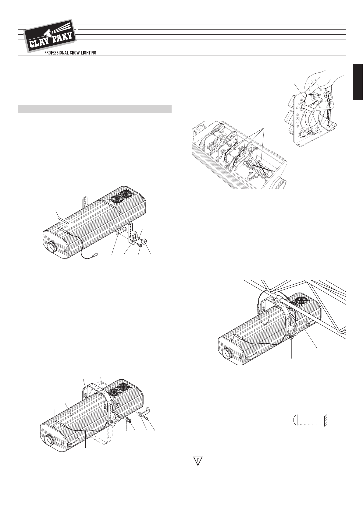
• Fitting the safety wire
The projector must never be erected without the safety wire (17). The wire is
secured to the gantry or other structure, then anchored to the eye bolts (4) on the
projector itself.
• Initial assembly operations
Position the block (2) over the threaded holes on the projector housing, offer
the graduated plate (3) and secure with the eyebolt (4), then fit the knob (5) and
washer (6).
Align the bracket (7) with the plates (3) so as to give the desired height, insert
the bushing (8), the countersunk washer (9) and the screw (10) in the selected
holes and secure with the Allen key supplied.
The bracket (7) can also be fitted from the underside of the projector by reversing the position of the graduated plates (3).
If the projector has been shipped
with plate (3) already fitted, before removing the plate (if necessary) remove the
safety bolt located inside the fixture in correspondence with eyebolt (4).
Adjust the bracket to the desired angle and secure by tightening the knobs (5).
Fix the safety wire (11) of the lamp access cover (12) to the graduated plate (3).
Fit the four side handles (13) with the screws (14) provided.
• Unpacking
Open the box, remove the projector from the packing and place it on a flat
horizontal surface.
Unpack the standard accessories supplied with the equipment. Inspect the lamp
change label (1) and replace with one of the optional language versions if
necessary.
Make certain that the label is never removed, as it displays important safety
information.
INSTALLING THE PROJECTOR
1
INSTRUCTION MANUAL
ENGLISH
15
16
• Installing the projector
The projector can be mounted any position without its operating characteristics being
affected.
IMPORTANT: fix the projector in the desired position utilizing the holes in the
bracket (7). Secure preferably using two ø12 bolts with nuts and lock washers.
Make certain that the anchorage is stable before positioning the projector.
• Removal of transit bands
Loosen the knob (15) and remove the lamp
access cover (12) from the projector.
Locate and remove all elastic transit bands
(16) from the colour, frost, prism and
zoom/focus lens drives.
Replace the cover and tighten the knob.
• Fitting the lamp
Refer to directions for replacement of the lamp given under heading 6 MAINTENANCE.
• Minimum distance from target objects
The projector must be positioned in such a way
that objects struck by the beam are located at least
2.5 m (8’ 2”) from the lens.
• Minimum distance of inflammable materials from any part of the equipment:
0.10 m (4”).
The appliance may be mounted on surfaces rated normally inflammable.
IMPORTANT: For better and more reliable operation of the projector, the ambient temperature must not exceed 35° C (95° F). Protection factor IP 20: the appliance is protected against penetration of solid bodies more than 12mm (0.5”) in diameter (first digit
2), but can be damaged by spray, jet, drip or rain water (second digit 0).
IMPORTANT: Read carefully. It is essential for the correct and safe use of the
equipment that erectors and operators should be fully conversant with the
information and instructions given in this manual.
3
6
5
2
1
4
4
17
SUPER SCAN ZOOM
HMI 1200
ENGLISH
14
13
10
9
3
11
15
12
8
7
®
(8’ 2”)
2.5 m
HMI 1200
Page 2

10
Having completed the operations described above, press the on/off switch (34).
Check that the warning light comes on and that the auto-reset sequence starts.
Projectors are wired up to the controller and one to the next using two-core screened
cable and Cannon 5 pin XLR type plug/socket connectors.
To connect a DMX line, a terminating plug (33) with a 100Ω resistor wired between
pins 2 and 3 must be fitted to the last projector connected in series; the plug is not
required when using a RS232/423(PMX) signal.
The wires must not come into contact with each other or with the metal casing of the plug.
The casing of the plug/socket must be connected to the screen and to pin 1
of the connectors.
SIGNAL
SCREEN
SIGNAL
54
3
2
1
SIGNAL
SCREEN
SIGNAL
RS232/423 (PMX)
1
2
3
45
DMX 512
• Connecting the control signals
RS 232/423 (PMX) - DMX 512
IMPORTANT: the projector must be connected to a power supply circuit having a proper earth system (Class I appliance).
• Selection of voltage/frequency
Open up the effects compartment of the projector by lifting the relative cover (see
heading 6 MAINTENANCE) and locate the voltage change terminal (29) mounted
to the effects assembly frame (30).
Use a screwdriver to disconnect the cable (31) from the terminal it occupies, and
reconnect to the terminal alongside, referring to the label (32) alongside the terminal. Having completed the operation, refit the cover.
• Fitting the mirror head
Fit the mirror head (19) to the projector and secure with the three knobs (20).
Connect the mirror head plug (21) to the socket (22) located on the front of the
projector.
Connect the metal safety wire (23) to the tag (24) on the projector.
• Changing the lens hood
Loosen the screws (25) a few turns without removing completely, then dislodge the
standard lens hood (26) by drawing it upwards and inwards, taking care to avoid
contact with the mirror.
Take the wide-angle mirror head lens hood (27) out of the projector packing, and
fit it in place of the standard hood.
Check that the lens hood is in the correct position (slots located fully behind the
screw heads), then retighten the screws.
Verify that the lens hood produces the required effect by selecting 100% TILT (with
dip-switch 6 off) and sliding the PAN control from 0% to 100%.
25
26
27
POWER SUPPLY AND INTERFACE
3
• Connecting to the electrical power supply
The operations described in this heading must be carried out by a licensed
electrician.
It is good policy to connect projectors to the power supply by way of dedicated switches, so that each can be turned on and off individually from a remote station.
The projector is designed to operate at the voltage and frequency indicated on the
electrical data plate (28) affixed to the rear end. Check that these two values correspond to the mains voltage and frequency, or if not, proceed as indicated below.
N
L
Mains
28
34
33
• Unpacking
Open the box, take out the mirror head, position it on a horizontal surface and remove
the elastic transit bands (18) from the Tilt motor.
INSTALLING THE MIRROR HEAD
2
30 29 32
31
18
24
20
21
22
19
23
RS 232/423
DMX 512
Page 3
11
654321
ON
+
COL
COL
COL
NORMAL
PAN
TILT
OFF
EXPANDED
0
1
2
3
4
5
6
7
8
9
10
The response of the iris to the
movement of the potentiometer is
linear and continuous through
0…25% of the adjustment range,
within which the slider can be
stopped in any position to obtain
the desired aperture diameter.
From 25% to 100% the diameter
remains fixed.
From 25% to 75% the gobo
rotates through 540° (1° turns).
From 75% all’87% the gobo turns
more quickly at first, then slows
down to a complete stop.
From 87% al 100% the gobo
begins turning in the opposite
direction, slowly at first and then
more quickly.
100% 100%
87%
75%
25% 25%
0%
• IRIS/GOBO ROTATION (12 channel operation) - channel 1
0°
360°
540°
STOP
OPTIONS
Having completed all the operations
indicated thus far, loosen the knobs (5),
manoeuvre the projector on the bracket
(7) until the beam is directed at centre
stage, then retighten the knobs (5).
• Adjusting the mirror head
The beam can be positioned not only by
moving the entire projector, but also by
adjusting the mirror head.
To do this, loosen the three knobs (20),
turn the mirror head to the desired position, and retighten the knobs.
7
5
20
180°
CHANNEL FUNCTIONS AND OPTIONS
5
Select the options by setting the dip-switches as indicated.
POSITIONING THE PROJECTOR
4
• Alignment procedure
Before positioning the projector, set the channels as shown in the following table:
CHANNEL
1 IRIS/GOBO ROTATION
2 COLOUR EFFECTS WHEEL
3 GOBO SELECTION
4 DIMMER/STOPPER/STROBE
5PAN
6 TILT
7 FROST/PRISM SELECTION AND ROTATION
8 ZOOM
9 FOCUS
10 CYAN
11 MAGENTA
12 YELLOW
POSITION OF SLIDER
100% (maximum aperture)
-
-
100 % (white beam)
50%
50%
0 % (white beam)
-
-
100% (white beam)
100% (white beam)
100% (white beam)
025
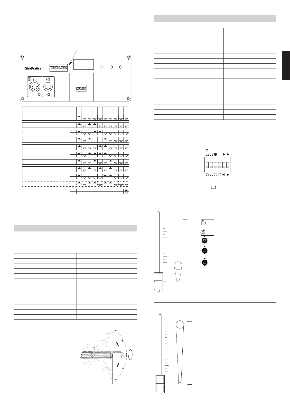
DIGITAL START ADDRESS SELECT
OPTION SELECT
DIGITAL INPUT LEDS
1
16
124816
1283264
TEST
256
ON
12 436578109
DIGITAL INPUT
109-120Projector - Channels10
97-108Projector - Channels9
85-96Projector - Channels8
73-84Projector - Channels7
61-72Projector - Channels6
49-60Projector - Channels5
37-48Projector - Channels4
25-36Projector - Channels3
2
1
ON
OFF
ON
OFF
ON
OFF
ON
OFF
ON
OFF
ON
OFF
ON
OFF
ON
OFF
124
8
163264
128
256
TEST
OFF
ON
OFF
ON
Projector - Channels 13-24
1-12Projector - Channels
CODE
OFF
ON
• Projector address codes
A single SUPER SCAN ZOOM projector utilizes 12 (Normal) or 16 (Expanded)
control channels. To ensure that the different projectors are addressed correctly
by the controller, a code must be assigned to each one.
The operation is carried out on each SUPER SCAN ZOOM by setting the dipswitches as indicated in the table below.
Setting the TEST switch to the ON position for a few seconds with the projector powered-up, an auto-reset routine is carried out. Leaving the TEST switch at the ON position for a longer period, a full self-test program will be completed; once the operation
has terminated, return the switch to the OFF position.
• IRIS (16 channel operation) - channel 1
0
1
2
3
4
5
6
7
8
9
10
The response of the iris to the movement of the potentiometer is linear and
continuous through the full 0…100%
range, so that the slider can be
stopped in any position to obtain the
desired aperture diameter.
100%
0%
IRIS
COLOUR EFFECTS WHEEL
STATIC GOBO SELECTION
DIMMER/STOPPER-STROBE
PA N
TILT
FROST
ZOOM
FOCUS
CYAN
MAGENTA
YELLOW
ROTATING GOBO SELECTION
GOBO ROTATION
PRISM SELECTION
PRISM ROTATION
12 CHANNEL OPERATION
(option 4 OFF)
16 CHANNEL OPERATION
(option 4 ON)
CHANNEL
1
2
3
4
5
6
7
8
9
10
11
12
13
14
15
16
IRIS/ GOBO ROTATION
COLOUR EFFECTS WHEEL
STATIC GOBO SELECTION
DIMMER/STOPPER-STROBE
PA N
TILT
FROST/PRISM SELECTION AND ROTATION
ZOOM
FOCUS
CYAN
MAGENTA
YELLOW
ENGLISH
Spotlight selection
Page 4

12
0
1
2
3
4
5
6
7
8
9
10
Yellow -Red
Green -Blue
White
Dark red
U.V. Filter
Warm filter
Blue with hole
Yellow with hole
Cold filter
0
1
2
3
4
5
6
7
8
9
10
Yellow -Red
Green -Blue
White
Dark red
U.V. Filter
Warm filter
Blue with hole
Yellow with hole
Cold filter
Standard operation
Changes of effect occur instantaneously across the full range of
adjustment from 0% to 100% as the
slider reaches different present levels on the graduated scale.
Operation with option 2 ON
The change of effect in response
to the movement of the potentiometer is linear and continuous,
so that the slider can be stopped in
intermediate positions to obtain a
two colour beam.
• COLOUR EFFECTS WHEEL - channel 2
0
1
2
3
4
5
6
7
8
9
10
Yellow -Red
Green -Blue
White
Dark red
U.V. Filter
Warm filter
Blue with hole
Yellow with hole
Cold filter
Operation with option 1 ON
In the 0% to 50% range of adjustment, operation is standard; from
50% to 100% the wheel rotates continuously with speed increasing
steadily from 0 to 300 rpm.
Operation with options 1 and 2 ON
In the 0% to 50% range of adjustment, operation is the same as with
option 2 ON.
From 50% to 100% the wheel rotates
continuously with speed increasing
steadily from 0 to 300 rpm.
• GOBO SELECTION (12 channel operation) - channel 3
Operation with option 3 ON
The sequence of effects is produced
as in standard operation, though the
beam darkens during the changeover.
This option remains inhibited during
continuous rotation of the wheel
(option 2 ON).
0
1
2
3
4
5
6
7
8
9
10
Yellow -Red
Green -Blue
White
Dark red
U.V. Filter
Warm filter
Blue with hole
Yellow with hole
Cold filter
Operation with options 1 and 3 ON
In the 0% to 50% range of adjustment, operation is the same as with
option 3 ON.
From 50% to 100% the wheel rotates
continuously with speed increasing
steadily from 0 to 300 rpm.
WHEEL 1
with rotating gobos
WHEEL 2
with fixed gobos
1 : 081314/001
2 : 081311/001
3 : 081325/001
4 : 081324/001
5 : 081308/001
6 : 081307/001
7 : 081306/001
8 : 081316/001
12 34 56
ON
OFF
+
ON
OFF
654321
10
9
8
7
6
5
4
3
2
1
0
Cold filter
Warm filter
Yellow with hole
Blue with hole
U.V. Filter
Dark red
Yellow -Red
Green -Blue
White
123456
ON
OFF
12 34 56
ON
OFF
10
9
8
7
6
Cold filter
5
Warm filter
4
Yellow with hole
3
Blue with hole
U.V. Filter
2
Dark red
1
Yellow -Red
Green -Blue
0
White
ON
OFF
654321
ON
OFF
654321
DISCO 1
con Gobos Rotanti
con Gobos Fissi
1
0
02
3
4
5
DISCO 2
8
7
6
Page 5

13
• STATIC GOBO SELECTION (16 channel operation) - channel 3
10
The change from one gobo to the next
in response to the movement of the
potentiometer is linear and continuous, so that the wheel can also be
stopped in intermediate positions.
0
1
2
3
4
5
6
7
8
9
10
OFF
ON
12 34 56
Standard operation
Vertical movement (Tilt) of the mirror
is linear and continuous in response to
the movement of the slider, occurring
gradually and uniformly between 0
and 10 on the scale.
The mirror can be stopped at any
angle within the range of adjustment.
• DIMMER/STOPPER/STROBE - channel 4
0
1
2
3
4
5
6
7
8
9
10
In the 0% to 50% range of adjustment,
the dimmer opens gradually to maximum
aperture.
Strobe effect is produced from 55% to
95%, with frequency increasing from 1 to
7 flashes per second.
The aperture remains fixed between
95% and 100% of the range.
0
1
2
3
4
5
6
7
8
9
10
654321
ON
OFF
OFF
ON
123456
0
1
2
3
4
5
6
7
8
9
10
Standard operation
Horizontal movement (Pan) of the mirror is linear and continuous in
response to the movement of the slider, occurring gradually and uniformly
between 0 and 10 on the scale.
The mirror can be stopped at any
angle within the range of adjustment.
Optional operation
The starting position and the direction
of movement can be reversed.
The panning movement of the mirror
is produced in exactly the same way
(see previous paragraph).
• PAN - channel 5
• TILT - channel 6
ENGLISH
WHEEL
1
0
WHELL
2
0
OPERATION
OF
WHEEL N°2
CHANGE
0
9
8
7
6
5
4
3
2
5
CHANGE
0
6
CHANGE
0
7
CHANGE
0
8
CHANGE
1
8
CHANGE +
REGOLATION
1
7
CHANGE +
REGOLATION
1
6
CHANGE +
REGOLATION
1
5
CHANGE +
REGOLATION
2
5
CHANGE +
REGOLATION
2
6
CHANGE +
REGOLATION
2
7
CHANGE +
REGOLATION
2
8
CHANGE +
REGOLATION
4
0
WHITE
3
0
WHITE
2
0
WHITE
1
1
0
WHITE
0
0
0
10
9
8
7
6
5
4
3
2
1
0
GOBO 4
GOBO 3
GOBO 2
GOBO 1
White
WHITE
Page 6

14
0
1
2
3
4
5
6
7
8
9
10
654321
ON
OFF
Optional operation
The starting position and the direction
of movement can be reversed.
The tilting movement of the mirror is
produced in exactly the same way
(see previous paragraph).
• FROST/PRISM SELECTION AND ROTATION (12 channel operation) - channel 7
0
1
2
3
4
5
6
7
8
9
10
Frost 1
Frost 2
Prisma 2
Stop
Stop
Prisma 1
Stop
Stop
White
•
ZOOM - channel 8
0
1
2
3
4
5
6
7
8
9
10
The projected image expands and
contracts gradually in response to the
movement of the slider, which can
therefore be set at any given position
to obtain a desired size.
The change of the frost filters and
prisms from one to another occurs
instantaneously in response to the
movement of the slider, whereas the
speed at which the prism rotates (in the
direction indicated) varies gradually.
• FROST (16 channel operation) - channel 7
0
1
2
3
4
5
6
7
8
9
10
Frost 1
Frost 2
White
The change from one frost filter to the
next occurs gradually in response to
the movement of the slider.
0
1
2
3
4
5
6
7
8
9
10
CIANO MAGENTA GIALLO
• FOCUS - channel 9
0
1
2
3
4
5
6
7
8
9
10
M
Electronic focus control is directly proportional to the movement of the slider and the projection distance.
The change occurs instantaneously
as the slider reaches different preset
levels on the graduated scale.
From 0% to 49.7% the gobo rotates
through 540° (1 _ turns).
From 50% to 75% the gobo turns
more quickly at first, then slows down
to a complete stop.
From 75.5% to 100% the gobo begins
turning in the opposite direction, slowly at first and then more quickly
• COLOUR MIX - channels 10 - 11 - 12
0
1
2
3
4
5
6
7
8
9
10 100%
STOP
75%
50%
0%
540°
360°
0°
0
1
2
3
4
5
6
7
8
9
10
GOBO 4
GOBO 3
GOBO 2
GOBO 1
White
channel 10 channel 11 channel 12
• ROTATING GOBO SELECTION (16 channel operation) - channel 13
• GOBO ROTATION (16 channel operation) - channel 14
RGB colour variation is linear
and continuous in response
to the movement of the sliders, which can be stopped at
any position to obtain the
desired hue.
The three colour channels can
be combined one with another
to obtain an infinite variety of
shades and hues.
RED GREEN BLUE
Page 7

15
MAINTENANCE
The change of prism occurs instantaneously as the slider reaches different
preset levels on the graduated scale.
0
1
2
3
4
5
6
7
8
9
10
White
• PRISM SELECTION (16 channel operation) - channel 15
From 0% to 49.7% the prism rotates
through 540° (1 1/2 turns).
From 50% to 75% the prism turns
more quickly at first, then slows down
to a complete stop.
From 75.5% to 100% the prism begins
turning in the opposite direction, slowly at first and then more quickly.
0
1
2
3
4
5
6
7
8
9
10 100%
STOP
50%
0%
• PRISM ROTATION (16 channel operation) - channel 16
6
IMPORTANT: for uniform distribution of the light
beam, the lamp must be positioned so that the
glass pip (37) on the bulb does not coincide with
the optical axis of the projector. With this in
mind, locate the pip as high up as possible.
• Opening the projector
Free the access cover (12) by loosening the knob (15), and remove from the projector. Once the necessary work has been completed, refit the cover (12) and retighten
the knob (15).
• Changing the lamp
Open the projector, loosen the two side nuts (35)
of the lamp to be changed and remove it from the
supports (36).
Remove the new lamp from its packaging, loosen
the two side nuts (35) and locate the lamp in the
supports (36). Finally, retighten the nuts.
35
36
IMPORTANT: isolate the projector from the electrical power supply before commencing maintenance work of any description.
The maximum temperature on the outer surface of the projector under normal
operating conditions is 90 °C (194° F).
After switching off, do not remove any part of the projector for at least 10 minutes,
as indicated on the lamp change label (1).
Once this time has elapsed, the risk of a lamp exploding is practically zero. If the
lamp needs changing, wait a further 20 minutes to avoid the risk of burns.
In the event of a lamp exploding, the appliance is designed to prevent fragments of glass
from being scattered. Lenses and clear filters supplied with the appliance must be fitted
at all times, and if visibly damaged must be replaced promptly with genuine spares.
CAUTION: The projector uses a high pressure discharge lamp with
external starter.
- When fitting a new lamp, read the manufacturer’s instructions carefully.
-
The lamp must always be changed without delay if damaged or deformed by heat.
ENGLISH
3735
15
1
12
• Zero setting the working hours and number of times the lamp is switched on
To zero the hours of the lamp’s life (“Bulb hours”) and the number of times it is
switched on (“Bulb strikes”) which are stored in the DMX Receiver microprocessor,
proceed as follows:
1. Set the TEST microswitch (38) to the ON position.
2. Shift the option 1 microswitch (39) from ON to OFF (or from OFF to ON) and vice
versa 3 times within a time of 6 seconds. If the procedure has been carried out
correctly, the three signal control LEDs (40) will light up simultaneously, while the
display (41) will go completely blank. This situation lasts for approximately
5 seconds.
3. Return the TEST microswitch (38) to the OFF position.
025
DIGITAL START ADDRESS SELECT
OPTION SELECT
DIGITAL INPUT LEDS
1
16
124816
1283264
TEST
256
ON
12 436578109
DIGITAL INPUT
38 41
39
40
43
42
45
44
• Changing the colour filters
Having opened the projector, identify the filter
to be changed, grip firmly between thumb and
forefinger and push against the spring clip
(42) until free of the fixed clips (43).
Bend the filter outwards and remove.
Offer the new filter to the spring clip (42) and
anchor behind the two fixed clips (43).
• Changing metal gobos
Having opened the projector, identify the gobo
to be replaced and push gently toward the
clips (44) until free.Take the selected replacement from the holder (45) on the gobos/iris
plate. Offer the new gobo to the two clips,
push gently and locate behind the third,
checking for flatness.
Page 8

• Routine cleaning
To maintain the light output of the projector
undiminished, parts that tend to accumulate
dust and grease must be cleaned periodically. In most circumstances the projector
will give long and trouble-free service if
these simple guidelines are followed.
To remove dirt from the lenses and filters, use
a soft cloth moistened with any liquid detergent suitable for cleaning glass.
IMPORTANT: do not use solvents or alcohol
Parts that need cleaning frequently.
Parts that need cleaning monthly.
The gobo wheel can be cleaned with a paintbrush.
Internal components should also be given a
general clean once a year, dislodging dust
and dirt with a brush and removing it simultaneously with a vacuum cleaner.
• Lubrication
To ensure that rotating gobos and prisms
continue to operate smoothly, the bearings
should be lubricated with oil every six
months: use only Kernite LUBE K AHT (p/n
164028/801).
Apply the oil using a syringe with a fine needle.
Avoid over-lubricating, as excess oil could
be spattered during rotation.
The rails of the focusing mechanism should
be cleaned and lubricated using a cloth
moistened with Kernite WAY-LUBE oil (p/n
172063/801).
• Lubrication of mirror head clutches
Check periodically that the grease applied
to the mirror pan and tilt clutches is in good
condition; if not, remove and regrease with
Kernite LUBE-K-AC (p/n 104034/801) to
ensure smooth and even movement of the
mirror.
16
TROUBLESHOOTING
7
TECHNICAL DATA
8
ELECTRICAL/MECHANICAL
SPECIFICATIONS
Power supply
• 220 - 240V 50Hz
• 200 - 220V 60Hz
Lamp
Metal iodide type with special built-in
power supply unit.
• Type of lamp: HMI 1200W
- Cap Sfc 15.5-6
- Colour temperature 6000 K
- Luminous flux 110,000 lumen
- Average life 750 h
Power consumption
• 1500 VA at 220V 50Hz
• correction factor 140µF standard
Motors
N. 20 microstepping motors with full
microprocessor control.
OPTICAL SYSTEM
Main optical unit in diecast aluminium,
incorporating twin lens condenser and a
reflector of high luminous efficiency.
CONTROL SYSTEMS
Channels
•
N.12 control channels (normal operation).
•
N.16 control channels (extended operation).
Inputs
The SUPER SCAN ZOOM is set up to
accept digital signals from controllers or
computers.
• Digital serial input:
RS232/423(PMX) or DMX 512
MIRROR HEAD
• Head rotatable through 360° on projector housing.
• Graduated scale for easy and accurate positioning.
• Anchorage for safety wire.
• Mirror of ultra high luminous efficiency.
Movement
• Produced by two µP controlled
microstepping motors.
• Infinitely variable speed of rotation;
maximum values:
- horizontal (PAN) = 0.4 sec (150°)
- vertical (TILT) = 0.3 sec (110°)
• Continuous and uniform movement.
Resolution:
- PAN = ±0.3° (150°)
- TILT = ±0.2° (110°)
CONSTRUCTION FEATURES
Safety devices
• Power supply shuts off automatically
in the event of overheating or cooling
system failure.
• Power shuts off automatically when
cover is opened.
Cooling
Forced ventilation cooling system
using axial flow fans.
Housing
• Extruded die-cast aluminium.
• Epoxy powder coated finish.
• Four side handles.
Mounting
• Steel bracket with epoxy powder
coated finish.
• Six installation positions, 25 mm (1”)
apart.
• Bracket adjustable through 100° with
graduated scale to assist positioning.
• Anchorage for safety wire.
Operating position
Will function in any position.
Weights and dimensions
• Projector 44.5 kg (97 lbs 14 ozs)
• Mirror head 3.1 kg ( 6 lbs 13 ozs)
(57.9”)
1470
(14.4”)
365
(17.1”)
434
(14.2”÷17.1”)
360÷435
No electrical power supply.
Lamp expended or faulty.
Check that power is available at the
mains socket.
Signal transmission cable
short-circuiting or disconnected.
Change cables.
Change lamp (see instructions).
Address codes incorrect.
Defect in electronic circuits. Contact an authorized technician.
Lenses broken. Contact an authorized technician.
See projector coding instructions.
Deposit of dust or grease. Clean (see instructions).
PROJECTOR DOES NOT LIGHT UP
ELECTRONICS NOT WORKING
FAULTS
PROJECTION FAULTY FAULTS
REDUCED BRIGHTNESS
POSSIBLE CAUSES CHECKS AND REMEDIES
•
••
•
•
••
•
•
 Loading...