

Page 1
PRELIMINARY
INSTRUCTION MANUAL
AN OSRAM BUSINESS
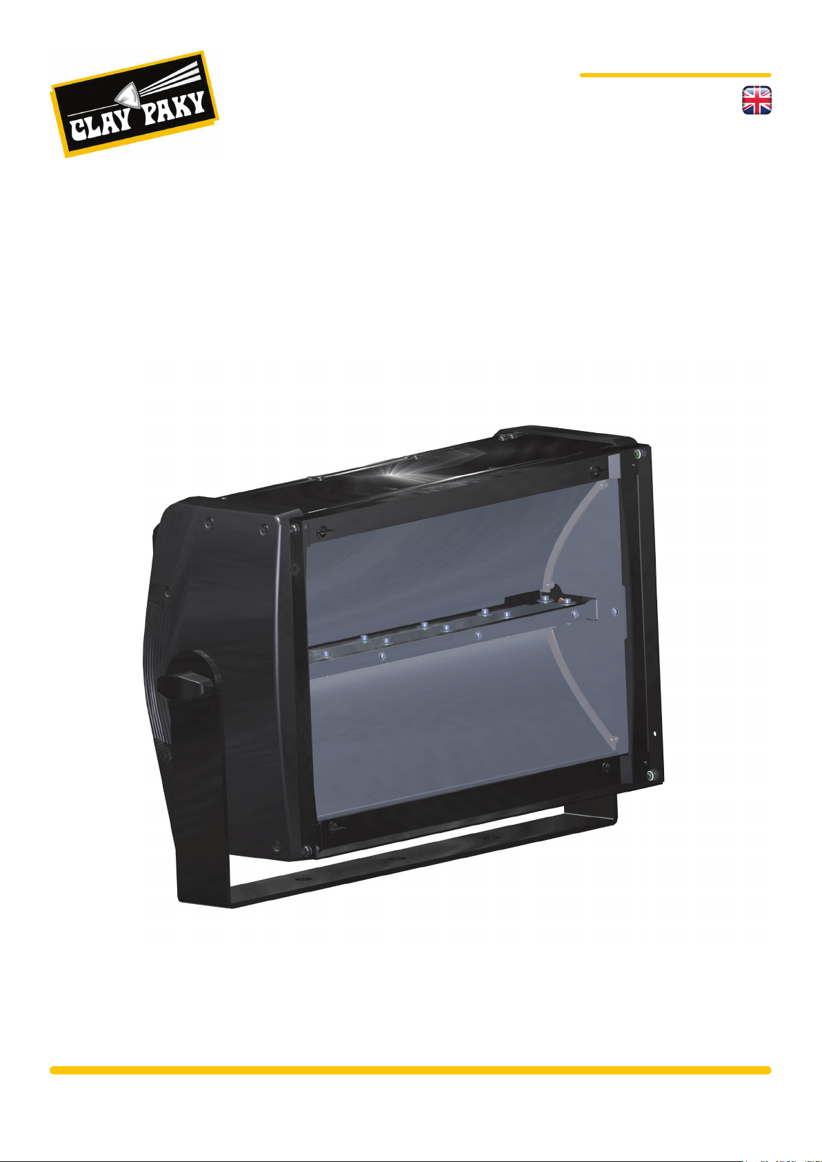
STORMY
STORMY CC
The latest LED technology meets the charm of a classic strobe
STORMY C71090
STORMY CC C71091
www.claypaky.it
Page 2
PRELIMINARY
PRELIMINARY
AN OSRAM BUSINESS
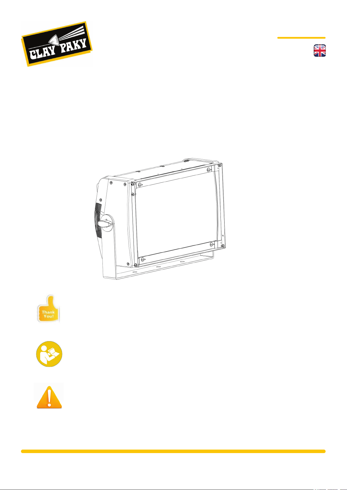
STORMY
STORMY CC
The latest LED technology meets the charm of a classic strobe
Congratulations on choosing a Clay Paky product!
We thank you for your choice. Please note that this product and all the others
in the rich Clay Paky range, has been designed and manufactured with total
quality to ensure excellent performance and best meet your expectations and
requirements.
Carefully read this instruction manual and keep in its entirety and keep it safe
for future reference.
It is essential to know the information supplied in this manual in order to ensure
that the tting is installed, used and serviced correctly and safely.
CLAY PAKY S.p.A. disclaims all liability for damage to the tting or to the other
property or persons deriving from installation, use and maintenance that have
not been carried out in conformity with this instructions manual, which must
always accompany the tting.
CLAY PAKY S.p.A. reserves the right to modify the characteristics stated in this
instructions manual at any time and channel list without prior notice.
www.claypaky.it
Page 3

PRELIMINARYPRELIMINARY
CONTENT
AN OSRAM BUSINESS
STORMY
STORMY CC
The latest LED technology meets the charm of a classic strobe
CONTENTS Pag.
1. Safety Information
1. Informazioni sulla sicurezza
1. Infomations sur la sécurité
1. Informationen zur sicherheit
1. Información sobre la seguridad
2. Unpacking And Preparation
3. Installation And Start-Up
4. Control Panel
5. Menu Setting
5.1 Set Up Menu
5.2 Options Menu
5.3 Information Menu
5.4 Manual Control Menu
5.5 Advanced Menu
6. Maintenance
4
5
6
7
8
9
11
12
14
15
15
16
17
17
18
7. Accessories
8. Technical Data
8.1/A Technical Data Stormy
8.1/B Technical Data Stormy CC
9. Channels
9.1/A Channel List Stormy
9.2/A Channel Function Stormy
9.1/B Channel List Stormy CC
9.2/B Channel Function Stormy CC
9.3 Duration Channels Details
9.4 Rete Channels Details
10. DURATION time - RATE time (PERIOD) relation
20
21
21
21
23
23
23
24
24
25
28
30
Page 4

PRELIMINARY
STORMY C71090
STORMY CC C71091
1. SAFETY INFORMATION
• Installation
Make sure all parts for xing the projector are in a good state of repair. Make sure the point of anchorage is
stable before positioning the projector. The safety chain must be properly hooked onto the tting and secu
red to the framework, so that, if the primary support system fails, the tting falls as little as possible. If the
safety chain gets used, it needs to be replaced with a genuine spare.
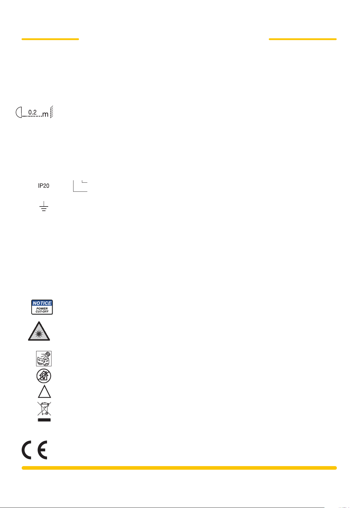
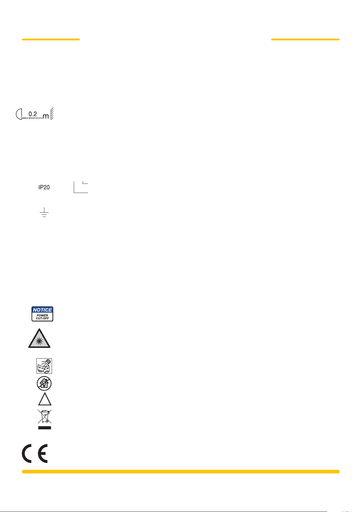
• Minimum distance of illuminated objects
The projector needs to be positioned so that the objects hit by the beam of light are at least 0.2 metres (8”)
from the lens of the projector.
• Minimum distance from ammable materials
The projector must be positioned so that any ammable materials are at least 0.20 metres (8") from every
point on the surface of the tting.
ta< 40 °C
tc ≤ 100 °C
• Maximum ambient temperature
Do not use the projector if ambient temperature (t
• IP20 protection rating
The protection rating of the tting is IP20. The meaning of the protection rating is:
IP 2 0
• Protection against electrical shock
Connection must be made to a power supply system tted with efcient earthing (Class I appliance accor
ding to standard EN 60598-1). It is, moreover, recommended to protect the supply lines of the projectors
from indirect contact and/or shorting to earth by using appropriately sized residual current devices.
• Connection to the power mains
A qualied electrician must perform connection to the power mains. Check that the mains frequency and
voltage correspond to the frequency and voltage for which the projector was designed and indicated on the
electrical data label. This label also gives the input power. Refer to the latter to evaluate the maximum num
ber of devices to be connected to the mains to avoid overloads.
The user must determine, in consultation with the supply authority, that the equipment is connected only to
a supply with a maximum permissible system impedence Zmax, at the interface point of the user's supply,
equal or lower to 0.23 Ω.
• External surface temperature
The maximum temperature that can be reached on the external surface of the tting, in a thermally steady
state, is 100°C (212°F).
• Maintenance
Before starting any maintenance work or cleaning the projector, cut off power from the supply mains. After
switching off, do not remove any parts of the tting for at least 10 minutes. The cover must be mounted and,
if visibly damaged, they have to be replaced with genuine spares.
Not protected against dripping water, rain, splashes or jets of water.
Protected against penetration by solid bodies of over 12mm (0.47”) in diameter.
) exceeds 40°C.
a
SAFETY INFORMATION
-
-
-
• Photobiological Safety
Risk Group 1
According to EN 62471
!
CAUTION. Do not look directly at the light source.
Do not look at the light beam with optical devices or any other tool that could cause light convergence.
• This product is intended for the following areas of application: studios, stages, theaters, exhibitions, trade
fairs, events, theme parks, entertainment venues, architectural lighting and similar.
• Not suitable for household illumination.
• Not for residential use.
• Disposing
This product is supplied in compliance with European Directive 2012/19/EU - Waste Electrical and Electro
nic Equipment (WEEE). To preserve the environment please dispose/recycle this product at the end of its
life according to the local regulation.
The products to which this manual refers comply with the following European Directives:
• 2006/95/EC - Safety of electrical equipment supplied at low voltage (LVD)
• 2004/108/EC - Electromagnetic Compatibility (EMC)
• 2011/65/EU - Restriction of the use of certain hazardous substances (RoHS)
• 2009/125/EC - EcoDesign requirements for Energy-related Products (ErP)
-
4
Page 5

PRELIMINARY
STORMY C71090
STORMY CC C71091
1. INFORMAZIONI SULLA SICUREZZA
• Installazione
Assicurarsi che tutte le parti per il ssaggio del dispositivo siano in buona condizione. Assicurarsi della stabilità del punto di
ancoraggio prima di posizionare il dispositivo. La fune di sicurezza deve essere opportunamente agganciata all’apparecchio
e ssata alla struttura di sostegno, deve essere installata in modo che, in caso di cedimento del sistema di supporto primario,
si abbia la minor caduta possibile dell’apparecchio. Dopo un eventuale intervento la fune di sicurezza deve essere sostituita
con il ricambio originale.
• Distanza minima degli oggetti illuminati
Il proiettore deve essere posizionato in modo tale che gli oggetti colpiti dal fascio luminoso siano distanti almeno 0,2 metri
(8 ") dalla lente del proiettore.
• Distanza minima da materiali inammabili
Il proiettore deve essere posizionato in modo tale che i materiali inammabili siano distanti almeno 0,20 metri (8 ") da ogni
punto della supercie dell’apparato.
ta< 40 °C
tc ≤ 100 °C
• Massima temperatura ambiente
Non utilizzare il proiettore se la temperatura ambiente (t
• Grado di protezione IP20
Il grado di protezione del raccordo è IP20. Il signicato del grado di protezione è:
) supera i 40 ° C.
a
IP 2 0
Non protetto nei confronti di gocce d’acqua, pioggia, spruzzi o getti d’acqua.
Protetto contro la penetrazione di corpi solidi di oltre 12 millimetri (0.47 ") di diametro.
• Protezione contro le scosse elettriche
Il collegamento deve essere fatto a un sistema di alimentazione dotato di un'efciente messa a terra (apparecchio di Classe
I secondo la norma EN 60598-1). Si raccomanda, inoltre, di proteggere le linee di alimentazione dei proiettori dai contatti
indiretti e/o cortocircuiti verso terra tramite l’uso di interruttori differenziali opportunamente dimensionati.
• Collegamento alla rete di alimentazione
Le operazioni di collegamento alla rete di distribuzione dell’energia elettrica devono essere effettuate da un installatore
elettrico qualicato. Vericare che frequenza e tensione della rete corrispondano alla frequenza ed alla tensione per cui il
proiettore è predisposto ed indicate sulla targhetta dei dati elettrici. Sulla medesima targhetta è pure indicata la potenza
assorbita. Fare riferimento a quest’ultima per valutare il numero massimo di apparecchi da collegare alla linea elettrica, al
ne di evitare sovraccarichi. L'utilizzatore deve assicurarsi, dopo aver consultato il proprio fornitore di energia elettrica, che
il dispositivo sia connesso solo ad un'alimentazione con un'impedenza massima ammissibile Zmax, al punto di interfaccia
dell'alimentazione utente, pari o inferiore a 0,23 Ω.
• Temperatura della supercie esterna
La temperatura massima raggiungibile sulle supercie esterna dell'apparecchio, in condizioni di regime termico, è di 100 °C
(212 °F).
• Manutenzione
Prima di iniziare qualsiasi operazione di manutenzione o pulizia del proiettore togliere la tensione dalla rete di alimentazio
ne. Dopo aver disalimentato il proiettore non rimuovere alcuna parte dell’apparato prima che sia trascorso un tempo di dieci
minuti. Le coperture devono essere montate e, se visibilmente danneggiate, devono essere sostituite con ricambi originali.
INFORMAZIONI
SULLA SICUREZZA
-
Gruppo di rischio 1
Secondo norma EN 62471
!
• Sicurezza fotobiologica
ATTENZIONE. Non guardare direttamente la sorgente di luce.
Non guardare il fascio di luce con strumenti ottici o altri strumenti che potrebbero causare convergenza di luce.
• Il prodotto è concepito per essere utilizzato nei seguenti ambiti: studi, palchi, teatri, esposizioni, ere, eventi, parchi a tema,
locali di intrattenimento, illuminazione architetturale e simili.
• Non adatto all'illuminazione domestica.
• Non per uso residenziale.
• Smaltimento
Questo dispositivo è conforme alla Direttiva Europea 2012/19/UE - Riuti di apparecchiature elettriche ed elettroniche (RAEE).
Nel rispetto dell'ambiente, smaltire/riciclare il prodotto al termine del suo ciclo di vita secondo le disposizioni di legge locali.
I prodotti a cui questo manuale si riferisce sono conformi alle Direttive della Comunità Europea di cui sono oggetto:
• 2006/95/CE - Sicurezza del materiale elettrico fornito a bassa tensione (LVD)
• 2004/108/CE - Compatibilità Elettromagnetica (EMC)
• 2011/65/EU - Restrizione dell'uso di determinate sostanze pericolose (RoHS)
• 2009/125/CE - Speciche per la progettazione ecocompatibile dei prodotti connessi all’energia (ErP)
5
Page 6
PRELIMINARY
STORMY C71090
STORMY CC C71091
1. INFORMATIONS SUR LA SÉCURITÉ
• Installation
Assurez-vous que toutes les pièces de xation de l'appareil sont en bon état. Assurer la stabilité du point d'ancrage avant de
placer le dispositif. Le câble de sécurité doit être correctement engagé à l’appareil et xé à la structure de support. En outre il
doit être installé pour avoir la mineure chute possible de l’appareil, en cas de défaillance du système de support principal. Après
une éventuelle intervention le câble de sécurité doit être remplacé avec une pièce de rechange originale.
• Distance minimum des objets éclairés
Le projecteur doit être placé de manière que les objets touchés par le faisceau lumineux sont distants au moins 0.2 m (8 ")
de la lentille du projecteur.
• Distance minimale des matériaux inammables
Le projecteur doit être placé de manière que les matériaux inammables sont distants au moins 0.2 m (8 ") de chaque point
de la surface du dispositif.
ta< 40 °C
tc ≤ 100 °C
• Température maximale ambiante
Ne pas utiliser le projecteur si la température ambiante (ta) dépasse 40 ° C.
• Degré de protection IP20
Le degré de protection de la jonction est IP20. Le sens de l'indice de protection est le suivant:
IP 2 0
Non protégé contre les gouttes d'eau, la pluie, les pulvérisations ou les jets d'eau.
Protégé contre la pénétration d'objets solides de plus de 12 mm (00:47 ") de diamètre.
• Protection contre les chocs électriques
La liaison doit être faite à un système d'alimentation ayant d’une mise à la terre efcace (appareil de classe I selon la norme
EN 60598-1). En outre, il est recommandé de protéger les lignes d'alimentation des projecteurs contre les contacts indirects
et/ou court-circuits à terre en utilisant des interrupteurs différentiels opportunément mesurés.
• La connexion au réseau électrique
Les opérations de branchement au réseau d'électricité doivent être effectués par un électricien qualié. Vériez que la fréq
uence et la tension du réseau correspondent à la fréquence et la tension pour lesquelles le projecteur est conçu comme indiqué sur l'étiquette des données électriques. L'étiquette indique également la puissance absorbée. Se référer à cette dernière
pour évaluer le numéro maximal de dispositifs qui peuvent être connectés à la ligne électrique, an d'éviter les surcharges.
L'utilisateur doit s’assurer, après la consultation de son fournisseur d'électricité, que l'appareil est connecté uniquement à
une alimentation avec une impédance maximale admissible Zmax, au point d'élément d'interface d'alimentation, , inférieure
ou égale à 0,23 Ω.
• Température de la surface extérieure
La température maximale atteinte sur la surface extérieure du dispositif est de 100 ° C (212 ° F), dans des conditions du
régime thermique.
• Maintenance
Débrancher le projecteur du réseau d'alimentation avant de commencer toute opération de maintenance ou de nettoyage.
Attendez dix minutes après avoir éteint le projecteur avant d’enlever une de ces parties. Les couvertures doivent être mon
tées et si elles sont visiblement endommagées, doivent être remplacées par des pièces de rechange originaires.
INFORMATIONS
SUR LA SÉCURITÉ
-
-
Groupe de risque 1
Selon la norme EN 62471
6
• La sécurité photobiologique
ATTENTION. Ne regardez pas directement la source de lumière. Ne regardez pas le faisceau de lumière avec des instru
ments optiques ou d'autres instruments qui pourraient provoquer la convergence de la lumière.
• Le produit est conçu pour être utilisé dans les espaces suivants: bureaux, scènes, théâtres, expositions, foires, événeme
nts, parcs à thème, des lieux de divertissement, éclairage architectural et analogues.
• N’est pas approprié pour l'éclairage domestique.
• Pas pour usage résidentiel.
!
• Elimination
Cet appareil est conforme à la directive européenne 2012/19/UE - Déchets des équipements électriques et électroniques
(DEEE).Pour protéger l'environnement, éliminer/recycler le produit à la n de son cycle de vie conformément à la législation
locale.
The products to which this manual refers comply with the following European Directives:
• 2006/95/EC - Safety of electrical equipment supplied at low voltage (LVD)
• 2004/108/EC - Electromagnetic Compatibility (EMC)
• 2011/65/EU - Restriction of the use of certain hazardous substances (RoHS)
• 2009/125/EC - EcoDesign requirements for Energy-related Products (ErP)
-
-
Page 7
PRELIMINARY
STORMY C71090
STORMY CC C71091
1. INFORMATIONEN ZUR SICHERHEIT
• Installation
Sicherstellen, dass sich alle Befestigungsteile des Geräts in gutem Zustand benden. Die Stabilität der Verankerungsstelle vor
der Anbringung des Geräts prüfen. Das Sicherheitsseil muss angemessen am Gerät eingehängt und an der Stützstruktur xiert
werden. Es ist so zu installieren, dass die Fallhöhe des Geräts bei einem Versagen des Hauptsupports so gering wie möglich
ist. Nach einem eventuellen Eingriff des Sicherheitsseils ist dieses unter Verwendung eines Original-Ersatzteils zu ersetzen.
• Mindestabstand zu den beleuchteten Gegenständen
Der Projektor muss so positioniert werden, dass die vom Lichtstrahl getroffenen Gegenstände mindestens 0,2 Meter (8 ")
von der Projektorlinse entfernt sind.
• Mindestabstand zu entzündlichen Materialien
Der Projektor muss so positioniert werden, dass entzündliche Materialien mindestens 0,20 Meter (8 ") von jedem Punkt der
Geräteoberäche entfernt sind.
ta< 40 °C
• Maximale Raumtemperatur
Der Projektor darf bei Raumtemperaturen (Ta) über 40 °C nicht vewendet werden.
• Schutzart IP20
Die Schutzart des Anschlusses entspricht IP20. Bedeutung der Schutzart:
IP 2 0
Kein Schutz gegen Tropfwasser, Regen, Spritz- oder Strahlwasser.
Geschützt gegen feste Fremdkörper mit Durchmesser ab 12 mm (0,47 ").
INFORMATIONEN
tc ≤ 100 °C
Risikoklasse 1
Gemäß EN 62471
• Schutz gegen Stromschlag
Der Anschluss muss an ein wirksam geerdetes Stromversorgungssystem erfolgen (Gerät der Klasse I gemäß EN 60598-1).
Darüber hinaus sind die Versorgungsleitungen der Projektoren mit entsprechend bemessenen Fehlerstromschutzschaltern
vor indirekten Kontakten bzw. Kurzschlüssen zu schützen.
• Anschluss an die Stromversorgungsleitung
Der Anschluss an das Stromversorgungsnetz muss von einem qualizierten Elektroinstallateur vorgenommen werden. Es ist
sicherzustellen, dass die Netzfrequenz und -spannung den Werten entsprechen, für die der Projektor ausgelegt ist und die
am Typenschild angeführt sind. Auf diesem Schild ist auch die Leistungsaufnahme angeführt. Um zu beurteilen, wie viele
Geräte maximal an die Stromleitung angeschlossen werden können, ohne diese zu überlasten, ist die Leistungsaufnahme
zu berücksichtigen. Der Benutzer hat nach der Einholung von Informationen bei seinem Stromanbieter sicherzustellen, dass
das Gerät nur an eine Versorgungsleitung mit einer maximal zulässigen Impedanz Zmax an der Schnittstelle der Benutzer
versorgung gleich oder unter 0,23 Ω angeschlossen wird.
• Temperatur der Oberäche
Die Geräteoberächen können bei Betriebstemperatur eine Höchsttemperatur von 100 °C (212 °F) erreichen.
• Instandhaltung
Vor Beginn von Instandhaltungs- oder Reinigungsarbeiten am Projektor ist Versorgungsspannung zu unterbrechen. Nach
dem die Stromversorgung zum Projektor abgeschalten wurde, müssen mindestens zehn Minuten vergehen, bevor irgendwelche Teile vom Gerät genommen werden. Die Abdeckungen müssen eingebaut werden; sollten sie sichtlich beschädigt
sein, müssen Sie durch Originalersatzteile ersetzt werden.
• Fotobiologische Sicherheit
ACHTUNG! Nicht direkt in die Lichtquelle blicken.
Keinesfalls mit optischen oder anderen Instrumenten, die das Licht bündeln könnten, in den Lichtstrahl blicken.
• Der Strahl ist zur Verwendung in folgenden Bereichen entwickelt: Studios, Bühnen, Theater, Ausstellungen, Messen, The
menparks, Unterhaltungslokale, architektonische Beleuchtung und Ähnliches.
-
-
-
• Nicht für die häusliche Beleuchtung geeignet.
• Nicht für Wohnzwecke.
!
• Entsorgung
Dieses Gerät entspricht der Europäischen Richtlinie 2012/19/EG über Elektro- und Elektronikaltgeräte (WEEE). Das Produkt
ist am Ende seiner Lebensdauer gemäß den örtlichen gesetzlichen Vorschriften zu entsorgen/recyceln.
The products to which this manual refers comply with the following European Directives:
• 2006/95/EC - Safety of electrical equipment supplied at low voltage (LVD)
• 2004/108/EC - Electromagnetic Compatibility (EMC)
• 2011/65/EU - Restriction of the use of certain hazardous substances (RoHS)
• 2009/125/EC - EcoDesign requirements for Energy-related Products (ErP)
7
Page 8
PRELIMINARY
STORMY C71090
STORMY CC C71091
1. INFORMACIÓN SOBRE LA SEGURIDAD
• Instalación
Asegurarse de que todos los elementos de jación del dispositivo estén en buenas condiciones. Asegurar la estabilidad del
punto de anclaje antes de colocar el dispositivo. La cuerda de seguridad deberá estar enganchada correctamente al aparato
y asegurada correctamente a la estructura de soporte. Ésta deberá iser instalada de manera que, en caso de fallo del sistema
de apoyo principal, el aparato sufra la menor caída posible. Después de una posible intervención la cuerda de seguridad debe
ser reemplazada con un recambio original.
• Distancia mínima de los objetos iluminados
El proyector deberá colocarse de manera que los objetos tocados por el haz de luz disten al menos 0,2 metros (8") de la
lente del proyector.
• Distancia mínima de materiales inamables
El proyector deberá colocarse de manera que los materiales inamables disten al menos 0,20 metros (8") de cualquier pun
to de la supercie del aparato.
ta< 40 °C
tc ≤ 100 °C
• Temperatura ambiente máxima
No usar el proyector si la temperatua ambiente (t
• Grado de protección IP20
El grado de protección de la instalación es de IP20. El signicado del grado de protección es:
) es superior a 40 ° C.
a
IP 2 0
No protegido contra gotas de agua, lluvia, salpicaduras o chorros de agua.
Protegido contra la penetración de cuerpos sólidos de más de 12 milímetros (0.47 ") de diámetro.
• Protección contra las descargas eléctricas
La conexión deberá hacerse a un sistema de alimentación con toma de tierra ecaz (aparato de Clase I según la norma EN
60598-1). Se recomienda proteger los cables de alimentación de los proyectores de los contactos indirectos y/o cortocircu
itos a tierra, mediante el uso de interruptores diferenciales de tamaño adecuado.
• Conexión a la red eléctrica
Las operaciones de conexión a la red eléctrica deben ser realizadas por un instalador eléctrico cualicado. Compruebe que
la frecuencia y el voltaje de la red corresponde a la frecuencia y a la tensión para la que el proyector ha sido diseñado se
gún lo indicado en la placa con las características. En esta placa se indica la potencia de entrada. Consulte ésta última para
evaluar el número máximo de aparatos que pueden ser conectados a la línea eléctrica, con el n de evitar sobrecargas. El
usuario debe vericar, tras haber consultado la empresa suministradora de electricidad, que el dispositivo esté conectado
únicamente a una fuente de alimentación con un máximo permitido de impedancia Zmax, hasta el punto de la interfaz de
alimentación, en o por debajo de 0,23 Ω.
• Temperatura de la supercie externa
La temperatura máxima que se puede alcanzar sobre la supercie externa del aparato, en condiciones térmicas estables ,
es de 100 °C (212 °F).
• Mantenimiento
Antes de iniciar cualquier operación de mantenimiento o limpieza del proyector, desconecte el aparato de la red eléctrica.
Tras haber apagado el proyector, no elimine ninguna parte del aparato antes de un período de diez minutos. Las cubiertas
deben ser montadas y, si son visiblemente dañadas, deben ser sustituidas por piezas originales.
INFORMACIÓN
SOBRE LA SEGURIDAD
-
-
-
Grupo de riesgo 1
Según norma EN 62471
8
• Seguridad fotobiológica
ATENCIÓN. No mirar directamente a la fuente de luz.
Non mirar el haz de luz con instrumentos ópticos u otros instrumentos que podrían causar convergencia de luz.
• El producto ha sido diseñado para ser usado en los siguientes espacios: estudios, escenarios, teatros, exposiciones, feri
as, eventos, parques temáticos, locales de entretenimiento, iluminación arquitectónica y similares.
• No es adecuado para la iluminación del hogar.
• No es adecuado para uso residencial.
!
• Reciclaje
Este dispositivo cumple con la Normativa Europea 2012/19/UE – Residuos de aparatos eléctricos y electrónicos (RAEE).
Para proteger el medio ambiente, recicle el producto al nal de su ciclo de vida según las disposiciones legales locales.
The products to which this manual refers comply with the following European Directives:
• 2006/95/EC - Safety of electrical equipment supplied at low voltage (LVD)
• 2004/108/EC - Electromagnetic Compatibility (EMC)
• 2011/65/EU - Restriction of the use of certain hazardous substances (RoHS)
• 2009/125/EC - EcoDesign requirements for Energy-related Products (ErP)
-
Page 9
PRELIMINARY
STORMY C71090
STORMY CC C71091
2. UNPACKING AND PREPARATION
1
UNPACKING AND
PREPARATION
PRELIMINARY
INSTRUCTION MANUAL
STORMY
STORMY CC
The latest LED technology meets the charm of a classic strobe
STORMY C71090
STORMY CC C71091
www.claypaky.it
Fig. 1 - Packing content
9
Page 10

PRELIMINARY
STORMY C71090
STORMY CC C71091
3. INSTALLATION AND START-UP
2
1 2
INSTALLATION AND
START-UP
4
3
5
Fig. 2 - Projector installation
The projector can be installed on the oor, on a truss, on the ceiling or wall. WARNING: the safety
chain must be installed except when the projector rests on the oor. (Code 105015/801 available upon request). This must be secured to the projector support structure and then ho-
oked to the fastening point at the centre of the xture.
10
Continued
Page 11

PRELIMINARY
STORMY C71090
STORMY CC C71091
3. INSTALLATION AND START-UP
3
INSTALLATION AND
START-UP
4
Fig. 3, 4 - Connecting and disconnecting the power cord
11
Page 12

STORMY C71090
STORMY CC C71091
4. CONTROL PANEL
5
Power
Supply
PRELIMINARY
CONTROL PANEL
6
Fig. 5 - Connection to the power mains
DMX 512
DMX 512
5 PIN
Fig. 6 - Connections to the control signal line (DMX)
Use a cable conforming to specications EIA RS-485: 2-pole twisted, shielded, 120Ω characteristic
impedance, 22-24 AWG, low capacity. Do not use microphone cable or other cable with characteri-
stics differing from those specied. End connections must be made using XLR type 3-pin male/female connectors. A terminating plug must be inserted on the last projector with a resistance of 120
(minimum 1/4 W) between terminals 2 and 3.
IMPORTANT: The wires must not make contact with each other or with the metal casing of the con-
nectors. The casing must be connected to the shield braid and pin 1 of the connectors.
12
Continued
Page 13

STORMY C71090
STORMY CC C71091
4. CONTROL PANEL
7
PRELIMINARY
CONTROL PANEL
Clay Paky
Menu settings status
If no button is pressed after a wait period (about 60 seconds) the display automatically returns to idle status.
Any modied value that has not yet been conrmed with the E key will be cancelled.
STORMY
Software release xxx
Adress xxx
Button functions – Menu SET
SELECT
S
DOWN
UP
• If pressed in idle status: Cyclically switches between idle status and menu settings.
• If pressed while setting a menu: Moves to an upper level without changing
anything (exits the function)
Decreases the value displayed (with auto-repetitions), or passes to the next item
on the menu. For quick access to the minimum parameter value, press the UP
key while holding down the DOWN key.
Increases the value displayed (with auto-repetitions), or passes to the previous
item on the menu. For quick access to the maximum parameter value, press the
DOWN key while holding down the UP key.
ENTER
Conrms the displayed value or activates the displayed function or opens the
next menu.
E
Display inversion
Fig. 7 - Switching on the projector
The projector immediately turns on when the power cord is plugged
To active this function press at the sa-
me time UP and DOWN keys while
the display is in standby.
The condition is memorized and saved even for the subsequent switching. To return to the initial state repeat the operation again.
13
Page 14

PRELIMINARY
STORMY C71090
STORMY CC C71091
5. MENU SETTING
Main Menu Level 1 Level 2 Level 3 Choices / Values
DMX Address 001-512
Standard
SET UP
OPTION
INFORMATION
MANUAL CONTROL
ADVANCED
Channel Mod
Fixture ID 001-255
Dimmer Curve
Minimum Ton Value 000-255
LED mode
Stormy CC only
Silent Mode
Display On / Off
Settings
Fixture hours
System Version
Driver diagnostic
DMX Monitor
Fans Monitor Power supply fan speed Speed xxxx RPM
Reset Yes / No
Channel
Access Code 1234
Xenon
Idependent
Curve 1
Curve 2
Raw
Balance
Standard
Quiet
Default preset Reset to default Yes / No
User preset 1
User preset 2
User preset 3
Fixiture hours
Lamp hours
Strobe rmware
Boot rmware
Driver rmware
CPU board
CPU SN
LED Temperature
Driver Temperature
LED channel CH1 - CH4 (R-G-B-W)
Red 000-255bit / 0-100%
Green 000-255bit / 0-100%
Blue 000-255bit / 0-100%
White 000-255bit / 0-100%
Intensity 000-255bit / 0-100%
Duration 000-255bit / 0-100%
Rate 000-255bit / 0-100%
Red 000-255bit / 0-100%
Green 000-255bit / 0-100%
Blue 000-255bit / 0-100%
Whjite 000-255bit / 0-100%
Intensity 000-255bit / 0-100%
Duration 000-255bit / 0-100%
Rate 000-255bit / 0-100%
Firmware uploader Yes / No
Model SetUp
Load preset 1 Yes / No
Save to preset 1 Yes / No
Load preset 2 Yes / No
Save to preset 2 Yes / No
Load preset 3 Yes / No
Save to preset 3 Yes / No
Current
Maximum
Minimum
Current
Maximum
Minimum
Undened mode
Stormy
Stormy CC
14
Page 15

PRELIMINARY
STORMY C71090
STORMY CC C71091
5.1 SET-UP MENU
SET UP - DMX ADDRESS
It allows to set DMX address to be assigned to the projector, it’s possible to select a DMX address between
1 and 512.
> NOTE: In case of absence of DMX input signal, the displayed projector address ashes.
SET UP - CHANNEL MODE
It allows to set the operation mode of the projector selecting from the following:
• Standard: max 7 DMX channels occupied for “Stormy CC” / max 3 DMX channels occupied for “Stormy”.
• Xenon: max 4 DMX channels occupied for “Stormy”
• Independent: max 14 DMX channels for “Stormy CC”
SET UP - FIXTURE ID
It allows to set a “Fixture ID” to be assigned to the projector, for easier identifcation of the same projector in
an installation. It’s possible to select a “Fixture ID” between 1 and 255.
5.2 OPTIONS MENU
OPTION - DIMMER CURVE
It allows the selection of one of the following two Dimmer curves:
• Curve 1
• Curve 2
OPTION - MINIMUM TON VALUE
It allows the set the minimum “T ON” duration of strobe ash under which it’s not possible to come down. It’s
possible to select a value between 0 and 255.
With the “Duration” channel you set the fash duration. At every level of the DMX signal corresponds
a duration. The value “Minimum T ON value” represents the level of the DMX channel Duration under which
the TON value does not change.
OPTION - LED MODE
It allows the selection of one of the following two methods of LEDs management
• Row: RGBW channels are independent.
• Balance: RGBW components are optimized to have a white color with maximum light output.
OPTION - SILENT MODE
It allows the selection of one of the following two alternatives:
• Standard: Maximum fans’ speed; therefore maximum noise level and maximum light output of the LEDs.
• Quiet:
It
type).
It reduces the fans’ speed and, as a consequence, the noise; the maximum brightness of the LEDs
reduces
also subject to decrease according to the conditions of use (ambient temperature, used effect
.
15
Page 16

PRELIMINARY
STORMY C71090
STORMY CC C71091
OPTIONS - DISPLAY
The enabled DISPLAY option (ON) allows to reduce the display backlight on the machine, after a 30 seconds
in standby mode. To restart is enough to press any key. Select OFF to disable this option.
OPTIONS - SETTING
It allows to save in the machine memory 3 different settings of the options menu items and its submenus:
• User preset 1
• User preset 2
• User preset 3
- Load preset 1, 2 o 3: It is used to display a previously confguration saved by the user.
- Save to preset 1, 2 o 3: It is used to save the current confguration set by the user.
• Default preset
It allows to reset to the default values (factory settings) on all the voices of the option menu and of the
related submenus.
5.3 INFORMATION MENU
INFORMATION MENU - SYSTEM VERSION
It allows to display the rmware/hardware versions of installed machine components:
Strobe rmware: Strobe application rmware
Boot rmware: Safety software
Driver rmware: Driver application rmware
CPU board: Hardware revision of CPU Board
CPU SN: Serial number of CPU Board
INFORMATION MENU - DRIVER DIAGNOSTIC - LED TEMPERATURE
It allows to display some details about the functionality of the card/cards and LEDs:
• Current: Instantly detected operating temperature
• Maximum: Maximum detected temperature
• Minimum: Minimum detected temperature
INFORMATION MENU - DRIVER DIAGNOSTIC - DRIVER TEMPERATURE
It allows to view some details about the functionality of the driver card for LED:
• Current: Instantly detected operating temperature
• Maximum: Maximum detected temperature
• Minimum: Minimum detected temperature
INFORMATION MENU - DRIVER DIAGNOSTIC - LED CHANNEL
It displays the diagnostics from the driver card: for each of the 4 channels a SYSTEM information and
a ERROR information is reported (the decoding is specifed in the driver’s specifcations).
16
Page 17

PRELIMINARY
STORMY C71090
STORMY CC C71091
INFORMATION MENU - DMX MONITOR
It allows to visualize the DMX input level (in bits or as a percentage) of each channel of the projector (value
Between 0 and 255 bit or between 0 and 100%).
INFORMATION MENU - FANS MONITOR
It allows to display the rotation speed (RPM Speed) of the fans installed on the machine.
PwrSp = Power Supply fans.
5.4 MANUAL CONTROL MENU
MANUAL CONTROL - RESET
It allows to reset the projector’s CPU in case of anomalies.
MANUAL CONTROL - CHANNEL
It allows to set a value in bit to the channels, from the projector control panel for manual control of each effect
without the need of a DMX input signal (values between 0 and 255 bits).
5.5 ADVANCED MENU
To access to the Advanced menu (only recommended for experienced users), you need to set the access
code 1234.
ADVANCED MENU - FIRMWARE UPLOAD
It allows to transfer the rmware from one projector to the others connected to it.
ADVANCED MENU - MODEL SETUP
It allows to change the projector’s model set, selecting among the available:
• Undened
• Stormy
• Stormy CC
17
Page 18

STORMY C71090
STORMY CC C71091
6. MAINTENANCE
8
PRELIMINARY
MAINTENANCE
2 Fusibili
6.3 x 32 mm 12AT
(p/n FUS001)
1
Fig. 8 - Fuses replacing
Each product has 2 fuses associated with the main power cord connection.
18
Continued
Page 19

STORMY C71090
STORMY CC C71091
6. MAINTENANCE
9
PRELIMINARY
MAINTENANCE
Parts requiring frequent cleaning.
Fig. 9 - Periodic cleaning
To ensure optimal operation and performance for a long time it is essential to periodically clean the
parts subject to dust and grease deposits. The frequency with which the following operations are
to be carried out depends on various factors such as wear and the work environment quality (air
humidity, dust, salinity, etc.). To remove dirt from external parts, use a soft cloth dampened with
any liquid glass cleaning detergent.
It is recommended that the projector undergoes an annual service by a qualied technician for
special maintenance involving at least the following operations:
• General cleaning of internal parts.
• General visual check of internal parts, cabling, mechanical parts, etc.
• Electrical, photometric and functional checks; eventual repairs.
IMPORTANT: Cleaning transparent cover
Only use neutral soap and water to clean the transparent cover then dry it carefully with a soft,
non-abrasive cloth. (WARNING: the use of alcohol or any other detergent could damage the
transparent cover.)
19
Page 20

STORMY C71090
STORMY CC C71091
7. ACCESSORIES
10
PRELIMINARY
ACCESSORIES
11
1
2
Fig. 10 - Barn-doors - C71116
20
Page 21

PRELIMINARY
STORMY C71090
STORMY CC C71091
8.1/A TECHNICAL DATA _ STORMY
TECHNICAL DATA
POWER SUPPLIES
INPUT POWER 850 VA
TOTAL LUMEN OUTPUT Max 80.000 lm
LIGHT SOURCE
CHANNELS
CONTROL INPUTS DMX 512
WEIGHT 7,5 Kg (15,87 lbs)
IP RATING
SAFETY DEVICES
COOLING Forced ventilation with fans and heat sink
BODY
WORKING POSITION
OPTICS
COLOR SYSTEM AND
EFFECTS SECTION
CONTROL AND
PROGRAMMING
ELECTRONICS
100/240V 50/60 Hz
Automatic power supply
144x8W(peak power) LED White
- Type: OSRAM OSLON SQUARE LED - GW CSSRM1.PC
- Color Temperature: 5.700 K
- Life: 50.000 hrs
- Luminous ux: 60.000 lm (continuous), 80.000 lm (peak)
3 channels DMX 512 Standard mode
4 channels DMX 512 Xenon mode
6 channels DMX 512 Extended mode (to come)
IP20
Protected against the entry of solid bodies larger than 12mm (0,47”)
No protection against the entry of liquids
Automatic shut-down in case of power supply overcurrent
Automatic power derating, in case of LED or power supply overheating or failed operation of cooling
system
Body extruded in black anodized aluminum
Aluminum and steel structure with plastic covers
Any working position
Hanging system: with clamps on the bracket
42° controlled light
130° direct + controlled light
Global dimmer
Strobe from 0,3 to 25 ashes/sec
Xenon lamp emulation
Extended range of macros
DMX protocol signal: USITT DMX 512
Display: Graphic LCD , backlit LED, white on black
Dimmer Resolution: 8 bit
Strobe 25Hz
DMX signal connection: 5 pole XLR input and output
Software upload through DMX input
Electronic monitoring with status error
Active Cooling system monitoring
DMX level monitoring on all channels
Internal data transmission diagnostics
Firmware upload from another xture
8.1/B TECHNICAL DATA _ STORMY CC
POWER SUPPLIES
INPUT POWER 850 VA
TOTAL LUMEN OUTPUT Max 40.000 lm
LIGHT SOURCE
100/240V 50/60 Hz
Automatic power supply
36x6W (peak power) LED - Type: OSRAM OSLON SIGNAL 120 - RED - LJ CKBP-JXKZ-27-1
36x7W (peak power) LED - Type: OSRAM OSLON SIGNAL 120 - GREEN - LT CQBP-KYLX-36-1
36x8W (peak power) LED - Type: OSRAM OSLON SQUARE LED - BLUE - LD CQAR-APAR-24-1
36x8W (peak power) LED - Type: OSRAM OSLON SQUARE LED – WHITE - GW CSSRM1.PC
- Color Temperature: 5.700 K
- Life: 50.000 hrs
- Luminous ux: 25.000 lm (continuous), 35.000 lm (peak)
Continued
21
Page 22

PRELIMINARY
STORMY C71090
STORMY CC C71091
7 channels DMX 512 Standard mode
CHANNELS
CONTROL INPUTS DMX 512
WEIGHT 7,5 Kg (15,87 lbs)
IP RATING
SAFETY DEVICES
COOLING Forced ventilation with fans and heat sink
BODY
WORKING POSITION
OPTICS
COLOR SYSTEM AND
EFFECTS SECTION
CONTROL AND
PROGRAMMING
10 channels DMX 512 Extended mode
14 channels DMX 512 Independent mode (to come)
IP20
Protected against the entry of solid bodies larger than 12mm (0,47”)
No protection against the entry of liquids
Automatic shut-down in case of power supply overcurrent
Automatic power derating, in case of LED or power supply overheating or failed operation of cooling
system
Body extruded in black anodized aluminum
Aluminum and steel structure with plastic covers
Any working position
Hanging system: with clamps on the bracket
42° controlled light
130° direct + controlled light
Global dimmer
Strobe from 0,3 to 25 ashes/sec
Xenon lamp emulation
Extended range of macros
Independent timing controls for each color
DMX protocol signal: USITT DMX 512
Display: Graphic LCD, backlit LED, white on black
Dimmer Resolution: 8 bit
Strobe 25Hz
DMX signal connection: 5 pole XLR input and output
Software upload through DMX input
TECHNICAL DATA
ELECTRONICS
Electronic monitoring with status error
Active Cooling system monitoring
DMX level monitoring on all channels
Internal data transmission diagnostics
Firmware upload from another xture
303
(11.93")
462
(18.18")
7.2 Kg
(15.13 Ibs)
305
(12.01")
22
152
(5.98")
Page 23

PRELIMINARY
STORMY C71090
9.1/A CHANNEL LIST _ STORMY
CHANNEL
1 INTENSITY INTENSITY
2 DURATION DURATION
3 RATE RATE
4 - MACRO
STANDARD XENON
CHANNEL MODE
9.2/A CHANNEL FUNCTION _ STORMY
Channel Mode
Standard Xenon
DMX
Value
0 - 5
6 - 255
0 - 255
0 - 5
6 - 255
0 - 5
6 - 42
43 - 85
86 - 128
129 - 171
172 - 214
215 - 255
INTENSITY
Light OFF
Light output linearly increase from minimum to maximum bright-
ness
DURATION
Light time (versus dark time) linearly increases from shorter time
(2.5msec) to longer time (650msec)
See details in a following dedicated table.
IMPORTANT:
Duration Time must be lower than Rate Time (Period) for ashing.
If Duration Time is equal or greater than Rate Time (Period) the
light is continuously on.
RATE
Light OFF
Flashing at linearly variable frequency from low:
(~0.3 ashes/sec or 1 ash every period of 3.5sec)
to high (25 ashes/sec or 1°ash every period of 40msec)
See details in a following dedicated table.
MACRO
Macro OFF
Macro 1 – UP ramp
Macro 2 – DOWN ramp
Macro 3 - UP↔DOWN ramp
Macro 4 – Random
Macro 5 – Lightning
Macro 6 – Spikes
CHANNELS
Function
23
Page 24

PRELIMINARY
STORMY CC C71091
9.1/B CHANNEL LIST _ STORMY CC
CHANNEL
1 RED RED
2 GREEN GREEN
3 BLUE BLUE
4 WHITE WHITE
5 INTENSITY INTENSITY
6 DURATION DURATION
7 RATE RATE
8 - BLU DURATION
9 - BLU RATE
10 - WHITE INTENSITY
11 - WHITE DURATION
12 - WHITE RATE
13 - MASTER INTENSITY
14 - MASK
STANDARD INDEPENDENT
CHANNEL MODE
CHANNELS
9.2/B CHANNEL FUNCTION _ STORMY CC
Channel Mode
Standard Independent
DMX
Value
0 - 255
0 - 255
0 - 5
6 - 255
0 - 255
0 - 255
Function
RED INTENSITY
Red colour linearly increase from no-light to maximum intensity
RED DURATION
Light time (versus dark time) linearly increases from shorter time
(2.5msec) to longer time (650msec)
See details in a following dedicated table.
IMPORTANT:
Duration Time must be lower than Rate Time (Period) for ashing.
If Duration Time is equal or greater than Rate Time (Period) the light
is continuously on.
RED RATE
Light OFF
Flashing at linearly variable frequency from low:
(~0.3 ashes/sec or 1 ash every period of 3.5sec)
to high (25 ashes/sec or 1°ash every period of 40msec)
See details in a following dedicated table.
GREEN INTENSITY
Green colour linearly increase from no-light to maximum intensity
GREEN DURATION
Light time (versus dark time) linearly increases from shorter time
(2.5msec) to longer time (650msec)
See details in a following dedicated table.
IMPORTANT:
Duration Time must be lower than Rate Time (Period) for ashing.
If Duration Time is equal or greater than Rate Time (Period) the light
is continuously on.
24
Continued
Page 25

PRELIMINARY
STORMY CC C71091
Channel Mode
Standard Independent
DMX
Value
0 - 5
6 - 255
0 - 255
0 - 255
0 - 5
6 - 255
0 - 255
0 - 255
0 - 5
6 - 255
0 - 5
6 - 255
0 - 255
CHANNELS
Function
GREEN RATE
Light OFF
Flashing at linearly variable frequency from low:
(~0.3 ashes/sec or 1 ash every period of 3.5sec)
to high (25 ashes/sec or 1°ash every period of 40msec)
See details in a following dedicated table.
BLUE INTENSITY
Blue colour linearly increase from no-light to maximum intensity
BLUE DURATION
Light time (versus dark time) linearly increases from shorter time
(2.5msec) to longer time (650msec)
See details in a following dedicated table.
IMPORTANT:
Duration Time must be lower than Rate Time (Period) for ashing.
If Duration Time is equal or greater than Rate Time (Period) the light
is continuously on.
BLUE RATE
Light OFF
Flashing at linearly variable frequency from low:
(~0.3 ashes/sec or 1 ash every period of 3.5sec)
to high (25 ashes/sec or 1°ash every period of 40msec)
See details in a following dedicated table.
WHITE INTENSITY
Blue colour linearly increase from no-light to maximum intensity
WHITE DURATION
Light time (versus dark time) linearly increases from shorter time
(2.5msec) to longer time (650msec)
See details in a following dedicated table.
IMPORTANT:
Duration Time must be lower than Rate Time (Period) for ashing.
If Duration Time is equal or greater than Rate Time (Period) the light
is continuously on.
WHITE RATE
Light OFF
Flashing at linearly variable frequency from low:
(~0.3 ashes/sec or 1 ash every period of 3.5sec)
to high (25 ashes/sec or 1°ash every period of 40msec)
See details in a following dedicated table.
MASTER INTENSITY
No Light output
Light output linearly increase from minimum to maximum brightness
DURATION
Light time (versus dark time) linearly increases from shorter time
(2.5msec) to longer time (650msec)
See details in a following dedicated table.
IMPORTANT:
Duration Time must be lower than Rate Time (Period) for ashing.
If Duration Time is equal or greater than Rate Time (Period) the light
is continuously on.
Continued
25
Page 26

PRELIMINARY
STORMY CC C71091
Channel Mode
Standard Independent
DMX
Value
RATE
0 - 5
6 - 255
0-31 No overwriting
32-47 RED overwrites all other channels
48-63 GREEN overwrites all other channels
64-79 BLUE overwrites all other channels
80-95 WHITE overwrites all other channels
96-11 RED,GREEN overwrite BLUE,WHITE
112-127 RED, BLUE overwrite GREEN,WHITE
128-143 RED,WHITE overwrite GREEN,BLUE
144-159 GREEN,BLUE overwrite RED,WHITE
160-175 GREEN,WHITE overwrite RED,BLUE
176-191 BLUE,WHITE overwrite RED, GREEN
192-207 RED,GREEN,BLUE overwrite WHITE
208-223 RED,GREEN,WHITE overwrite BLUE
224-239 RED,BLUE,WHITE overwrite GREEN
240-255 GREEN,BLUE,WHITE overwrite RED
Light OFF
Flashing at linearly variable frequency from low:
(~0.3 ashes/sec or 1 ash every period of 3.5sec)
to high (25 ashes/sec or 1°ash every period of 40msec)
See details in a following dedicated table.
MASK
Function
CHANNELS
26
Page 27

PRELIMINARY
STORMY C71090
STORMY CC C71091
9.3 DURATION CHANNEL DETAILS
CHANNELS
DMX
level
Time
[msec]
0 2.50
1 5.00
2 7.60
3 10.10
4 12.60
5 15.20
6 17.70
7 20.30
8 22.80
9 25.30
10 27.90
11 30.40
12 33.00
13 35.50
14 38.00
15 40.60
16 43.10
17 45.70
18 48.20
19 50.70
20 53.30
21 55.80
22 58.30
23 60.90
24 63.40
25 66.00
26 68.50
27 71.00
28 73.60
29 76.10
30 78.70
31 81.20
32 83.70
33 86.30
34 88.80
35 91.40
36 93.90
37 96.40
38 99.00
39 101.5
40 104.1
41 106.6
42 109.1
DMX
level
Time
[msec]
43 111.7
44 114.2
45 116.7
46 119.3
47 121.8
48 124.4
49 126.9
50 129.4
51 132.0
52 134.5
53 137.1
54 139.6
55 142.1
56 144.7
57 147.2
58 149.8
59 152.3
60 154.8
61 157.4
62 159.9
63 162.5
64 165.0
65 167.5
66 170.1
67 172.6
68 175.1
69 177.7
70 180.2
71 182.8
72 185.3
73 187.8
74 190.4
75 192.9
76 195.5
77 198.0
78 200.5
79 203.1
80 205.6
81 208.2
82 210.7
83 213.2
84 215.8
85 218.3
DMX
level
Time
[msec]
86 220.8
87 223.4
88 225.9
89 228.5
90 231.0
91 233.5
92 236.1
93 238.6
94 241.2
95 243.7
96 246.2
97 248.8
98 251.3
99 253.9
100 256.4
101 258.9
102 261.5
103 264.0
104 266.6
105 269.1
106 271.6
107 274.2
108 276.7
109 279.2
110 281.8
111 284.3
112 286.9
113 289.4
114 291.9
115 294.5
116 297.0
117 299.6
118 302.1
119 304.6
120 307.2
121 309.7
122 312.3
123 314.8
124 317.3
125 319.9
126 322.4
127 325.0
128 327.5
DMX
level
Time
[msec]
129 330.0
130 332.6
131 335.1
132 337.6
133 340.2
134 342.7
135 345.3
136 347.8
137 350.3
138 352.9
139 355.4
140 358.0
141 360.5
142 363.0
143 365.6
144 368.1
145 370.7
146 373.2
147 375.7
148 378.3
149 380.8
150 383.3
151 385.9
152 388.4
153 391.0
154 393.5
155 396.0
156 398.6
157 401.1
158 403.7
159 406.2
160 408.7
161 411.3
162 413.8
163 416.4
164 418.9
165 421.4
166 424.0
167 426.5
168 429.1
169 431.6
170 434.1
171 436.7
DMX
level
Time
[msec]
172 439.2
173 441.7
174 444.3
175 446.8
176 449.4
177 451.9
178 454.4
179 457.0
180 459.5
181 462.1
182 464.6
183 467.1
184 469.7
185 472.2
186 474.8
187 477.3
188 479.8
189 482.4
190 484.9
191 487.5
192 490.0
193 492.5
194 495.1
195 497.6
196 500.1
197 502.7
198 505.2
199 507.8
200 510.3
201 512.8
202 515.4
203 517.9
204 520.5
205 523.0
206 525.5
207 528.1
208 530.6
209 533.2
210 535.7
211 538.2
212 540.8
213 543.3
214 545.8
DMX
level
Time
[msec]
215 548.4
216 550.9
217 553.5
218 556.0
219 558.5
220 561.1
221 563.6
222 566.2
223 568.7
224 571.2
225 573.8
226 576.3
227 578.9
228 581.4
229 583.9
230 586.5
231 589.0
232 591.6
233 594.1
234 596.6
235 599.2
236 601.7
237 604.2
238 606.8
239 609.3
240 611.9
241 614.4
242 616.9
243 619.5
244 622.0
245 624.6
246 627.1
247 629.6
248 632.2
249 634.7
250 637.3
251 639.8
252 642.3
253 644.9
254 647.4
255 650.0
27
Page 28

PRELIMINARY
STORMY C71090
STORMY CC C71091
9.4 RATE CHANNEL DETAILS
CHANNELS
DMX
level
Time
[msec]
Frequency
[ash/sec]
0 - 0
1 - 0
2 - 0
3 - 0
4 - 0
5 - 0
6 3500 0.29
7 3500 0.29
8 2320 0.43
9 2320 0.43
10 1760 0.57
11 1760 0.57
12 1400 0.71
13 1400 0.71
14 1160 0.86
15 1160 0.86
16 1000 1.00
17 1000 1.00
18 880.0 1.14
19 880.0 1.14
20 760.0 1.32
21 740.0 1.35
22 720.0 1.39
23 700.0 1.43
24 640.0 1.56
25 600.0 1.67
26 580.0 1.72
27 570.0 1.75
28 560.0 1.79
29 540.0 1.85
30 500.0 2.00
31 490.0 2.04
32 480.0 2.08
33 460.0 2.17
34 440.0 2.27
35 430.0 2.33
36 420.0 2.38
37 410.0 2.44
38 400.0 2.50
39 390.0 2.56
40 384.0 2.60
41 376.0 2.66
42 360.0 2.78
DMX
level
Time
[msec]
Frequency
[ash/sec]
43 350.0 2.86
44 336.0 2.98
45 330.0 3.03
46 320.0 3.13
47 315.0 3.17
48 310.0 3.23
49 305.0 3.28
50 300.0 3.33
51 290.0 3.45
52 284.0 3.52
53 280.0 3.57
54 275.0 3.64
55 270.0 3.70
56 264.0 3.79
57 255.0 3.92
58 250.0 4.00
59 245.0 4.08
60 240.0 4.17
61 237.0 4.22
62 234.0 4.27
63 231.0 4.33
64 227.0 4.41
65 224.0 4.46
66 220.0 4.55
67 217.0 4.61
68 214.0 4.67
69 211.0 4.74
70 208.0 4.81
71 205.0 4.88
72 200.0 5.00
73 197.5 5.06
74 195.0 5.13
75 192.5 5.19
76 190.0 5.26
77 187.5 5.33
78 185.0 5.41
79 182.5 5.48
80 180.0 5.56
81 178.0 5.62
82 176.0 5.68
83 174.0 5.75
84 172.0 5.81
85 170.0 5.88
DMX
level
Time
[msec]
Frequency
[ash/sec]
86 168.0 5.95
87 166.0 6.02
88 164.0 6.10
89 162.0 6.17
90 160.0 6.25
91 158.0 6.33
92 156.0 6.41
93 154.0 6.49
94 152.0 6.58
95 151.0 6.62
96 150.0 6.67
97 149.0 6.71
98 148.0 6.76
99 147.0 6.80
100 146.0 6.85
101 145.0 6.90
102 144.0 6.94
103 142.0 7.04
104 140.0 7.14
105 138.0 7.25
106 136.0 7.35
107 134.0 7.46
108 132.0 7.58
109 130.0 7.69
110 128.0 7.81
111 127.0 7.87
112 126.0 7.94
113 125.0 8.00
114 124.0 8.06
115 123.0 8.13
116 122.0 8.20
117 121.0 8.26
118 120.0 8.33
119 119.0 8.40
120 118.0 8.47
121 117.0 8.55
122 116.0 8.62
123 115.0 8.70
124 114.0 8.77
125 113.0 8.85
126 112.0 8.93
127 111.0 9.01
128 110.0 9.09
28
Continued
Page 29

PRELIMINARY
STORMY C71090
STORMY CC C71091
9.4 RATE CHANNEL DETAILS
CHANNELS
DMX
level
Time
[msec]
Frequency
[ash/sec]
129 109.0 9.17
130 110.0 9.09
131 109.5 9.13
132 109 9.17
133 108.5 9.22
134 108.0 9.26
135 107.5 9.30
136 107.0 9.35
137 106.5 9.39
138 106.0 9.43
139 105.5 9.48
140 105.0 9.52
141 104.5 9.57
142 104.0 9.62
143 103.0 9.71
144 102.0 9.80
145 101.0 9.90
146 100.0 10.00
147 99.0 10.10
148 98.0 10.20
149 97.0 10.31
150 96.0 10.42
151 95.0 10.53
152 94.0 10.64
153 93.0 10.75
154 92.0 10.87
155 91.0 10.99
156 90.0 11.11
157 89.5 11.17
158 89.0 11.24
159 88.5 11.30
160 88.0 11.36
161 87.5 11.43
162 87.0 11.49
163 86.5 11.56
164 86.0 11.63
165 85.5 11.70
166 85.0 11.76
167 84.5 11.83
168 84.0 11.90
169 83.5 11.98
170 83.0 12.05
171 82.5 12.12
172 82.0 12.20
DMX
level
Time
[msec]
Frequency
[ash/sec]
173 81.5 12.27
174 81.0 12.35
175 80.5 12.42
176 80.0 12.50
177 79.6 12.56
178 79.2 12.63
179 78.8 12.69
180 78.4 12.76
181 78.0 12.82
182 77.6 12.89
183 77.2 12.95
184 76.8 13.02
185 76.4 13.09
186 76.0 13.16
187 75.6 13.23
188 75.2 13.30
189 74.8 13.37
190 74.4 13.44
191 74.0 13.51
192 73.6 13.59
193 73.2 13.66
194 72.8 13.74
195 72.4 13.81
196 72.0 13.89
197 71.6 13.97
198 71.2 14.04
199 70.8 14.12
200 70.4 14.20
201 70.0 14.29
202 69.6 14.37
203 69.2 14.45
204 69.0 14.49
205 68.7 14.56
206 68.4 14.62
207 68.1 14.68
208 67.8 14.75
209 67.5 14.81
210 67.2 14.88
211 66.9 14.95
212 66.6 15.02
213 66.3 15.08
214 66.0 15.15
215 65.7 15.22
216 65.4 15.29
DMX
level
Time
[msec]
Frequency
[ash/sec]
217 65.1 15.36
218 64.8 15.43
219 64.5 15.50
220 64.2 15.58
221 63.9 15.65
222 63.6 15.72
223 63.3 15.80
224 63.0 15.87
225 62.7 15.95
226 62.4 16.03
227 62.1 16.10
228 61.8 16.18
229 61.5 16.26
230 61.2 16.34
231 60.9 16.42
232 60.6 16.50
233 60.3 16.58
234 60.0 16.67
235 59.0 16.95
236 58.0 17.24
237 57.0 17.54
238 56.0 17.86
239 55.0 18.18
240 54.0 18.52
241 53.0 18.87
242 52.0 19.23
243 51.0 19.61
244 50.0 20.00
245 49.0 20.41
246 48.0 20.83
247 47.0 21.28
248 46.0 21.74
249 45.0 22.22
250 44.0 22.73
251 43.0 23.26
252 42.0 23.81
253 41.0 24.39
254 40.0 25.00
255 40.0 25.00
29
Page 30

PRELIMINARY
Duration time < Period : Flashing
Duration time >= Period : Light continuously ON
time
Period
(Rate time)
Duration
Dark
Light
Dark
Light
Duty
Cycle
[%]
MAX CURRENT vs DUTY CYCLE
MAX
30
100
SUBM AX
Max
Current
CONT
25
MAX
RED: 2.0A
GREEN: 2.0A
BLUE: 2.4A
WHITE: 2.4A
CURRENT VALUES
SUBMAX
RED: 1.5A
GREEN: 1.5A
BLUE: 2.0A
WHITE: 2.0A
CONT
RED: 1.0A
GREEN: 1.0A
BLUE: 1.5A
WHITE: 1.5A
STORMY C71090
STORMY CC C71091
Rate Time (Period) Relation
10. DURATION time - RATE time (PERIOD) relation
Duration Time
Max
Current
MAX
SUBM AX
CONT
MAX CURRENT vs DUTY CYCLE
25
30
CURRENT VALUES
MAX
RED: 2.0A
GREEN: 2.0A
BLUE: 2.4A
WHITE: 2.4A
RED: 1.5A
GREEN: 1.5A
BLUE: 2.0A
WHITE: 2.0A
SUBMAX
RED: 1.0A
GREEN: 1.0A
BLUE: 1.5A
WHITE: 1.5A
100
CONT
Duty
Cycle
[%]
Current
MAX
SUBM AX
CONT
Max
MAX CURRENT vs TIME ON
CURRENT VALUES
MAX
RED: 2.0A
GREEN: 2.0A
BLUE: 2.4A
WHITE: 2.4A
20
100
SUBMAX
RED: 1.5A
GREEN: 1.5A
BLUE: 2.0A
WHITE: 2.0A
CONT
RED: 1.0A
GREEN: 1.0A
BLUE: 1.5A
WHITE: 1.5A
TIME ON
500
[ms]
30
IST00H/001 Rev. PRELIMINARY (03/2015)
 Loading...