

Page 1
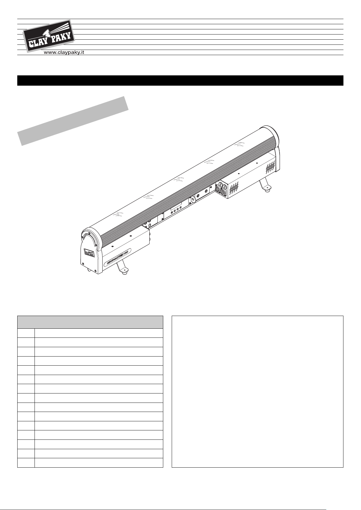
SHOW BATTEN 100
®
ENGLISH
SHOW BATTEN 100 AS
C71085
C71086
INSTRUCTIONS MANUAL
RY
A
ELIMIN
PR
Pag.
2
3
3
3
5
7
9
10
10
12
13
15
16
17
CONTENTS
Contents
Safety information SHOW BATTEN 100
Unpacking and preparation
Removal of the protective film
Installation and start-up
Control panel
Menu Setting
Set Up menu
Options menu
Information menu
Manual control menu
Maintenance
Technical data
Channel list
Channel functions
Congratulations on choosing a Clay Paky product!
We thank you for your choice. Please note that this product,
as all the others in the rich Clay Paky range, has been
designed and manufactured with total quality to ensure
excellent performance and best meet your expectations and
requirements.
Carefully read this instruction manual in its entirety and keep it
safe for future reference.
It is essential to know the information and comply with the
instructions given in this manual in order to ensure the fitting is
installed, used and serviced correctly and safely.
CLAY PAKY S.p.A. disclaims all liability for damage to the
fitting or to the other property or persons deriving from
installation, use and maintenance that have not been carried
out in conformity with this instructions manual, which must
always accompany the fitting.
CLAY PAKY S.p.A. reserves the right to modify the
characteristics stated in this instructions manual at any time and
without prior notice.
1
Page 2
0.2
100°C
IP20
AFETY INFORMATION SHOW BATTEN 100
S
• Installation
Make sure all parts for fixing the projector are in a good state of repair. Make sure the point of
nchorage is stable before positioning the projector.
a
The safety chain must be properly hooked onto the fitting and secured to the framework, so that,
if the primary support system fails, the fitting falls as little as possible. If the safety chain gets used,
it needs to be replaced with a genuine spare.
• Minimum distance of illuminated objects
The projector needs to be positioned so that the objects hit by the beam of light are at least 0.2
metres (8”) from the lens of the projector.
• Minimum distance from flammable materials
The projector must be positioned so that any flammable materials are at least 0.20 metres (8") from
very point on the surface of the fitting.
e
• Mounting surfaces
It is permissible to mount the fitting on normally flammable surfaces.
• Maximum ambient temperature
Do not use the project if ambient temperature (Ta) exceeds 40°C.
• IP20 protection rating
The fitting is protected against penetration by solid bodies of over 12mm (0.47”) in diameter (first
digit 2), but not against dripping water, rain, splashes or jets of water (second digit 0).
• Protection against electrical shock
Connection must be made to a power supply system fitted with efficient earthing (Class I appliance
according to standard EN 60598-1).
It is, moreover, recommended to protect the supply lines of the projectors from indirect contact
and/or shorting to earth by using appropriately sized residual current devices.
LiFePO4
• Connection to the power mains
A qualified electrician must perform connection to the power mains.
Check that the mains frequency and voltage correspond to the frequency and voltage for which the
projector was designed and indicated on the electrical data label.
This label also gives the input power. Refer to the latter to evaluate the maximum number of
devices to be connected to the mains to avoid overloads.
• External surface temperature
The maximum temperature that can be reached on the external surface of the fitting, in a thermally
steady state, is 100°C (212°F).
• Maintenance
Before starting any maintenance work or cleaning the projector, cut off power from the supply
mains. After switching off, do not remove any parts of the fitting for at least 10 minutes. The lenses
must be mounted and, if visibly damaged, they have to be replaced with genuine spares.
• Battery
This product contains a lithium iron tetraphosphate rechargeable battery. To protect the
environment, please discard the battery at the end of its life cycle according to current law.
NOT FOR RESIDENTIAL USE
SHOW BATTEN 100
The products to which this manual refers comply with the European Directives pursuant to:
• 2006/95/EC - Safety of electrical equipment supplied at low voltage (LVD)
• 2004/108/EC - Electromagnetic Compatibility (EMC)
• 2011/65/EU - Restriction of the use of certain hazardous substances (RoHS)
2
Page 3
2 x 183102/805
1
1
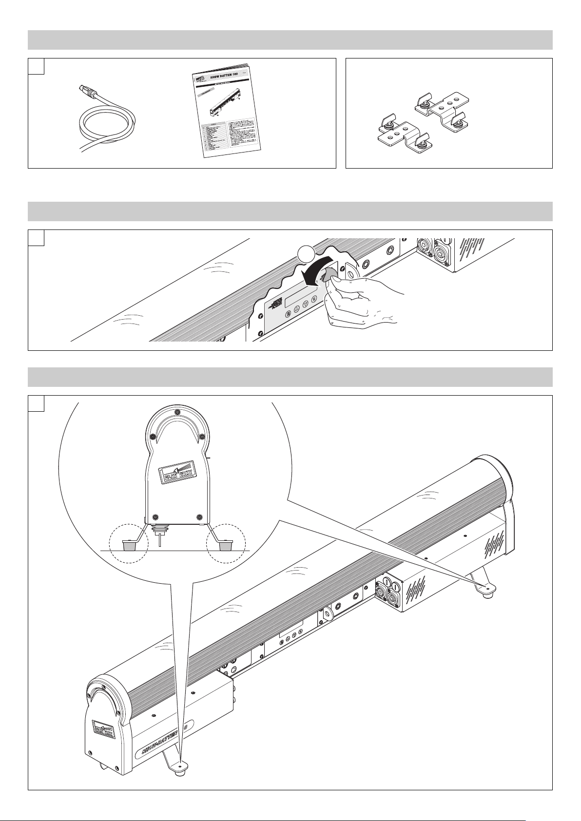
Packing content - Fig. 1
2
NPACKING AND PREPARATION
U
IST007/001
REMOVAL OF THE PROTECTIVE FILM
available
upon request
3
INSTALLATION AND START-UP
SHOW BATTEN 100
3
Continued
➔
Page 4
1
2
3
3
4
4
2
4
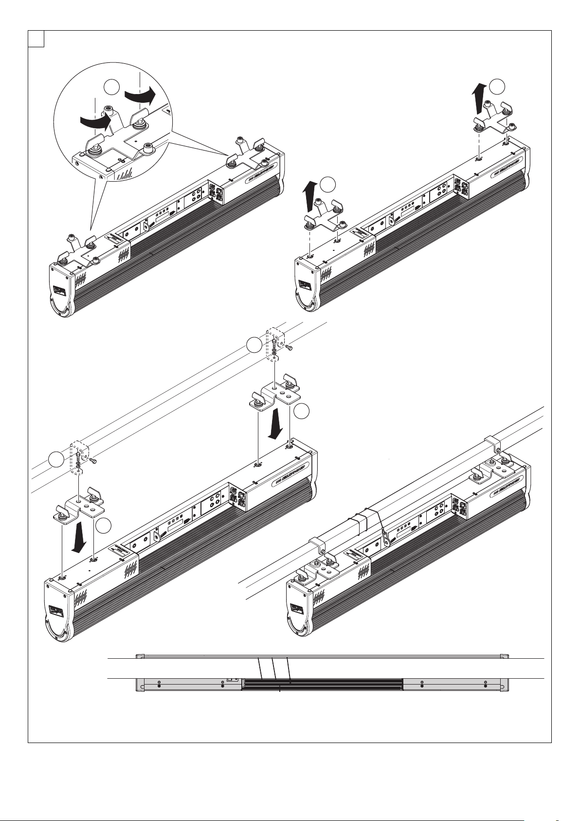
Projector installation - Fig. 4
The projector can be installed on the floor resting on specific rubber feet, on a truss, on the ceiling or wall.
WARNING: the safety chain must be installed except when the projector rests on the floor. (Code 105015/801 available upon request).
This must be secured to the projector support structure and then hooked to the fastening point at the centre of the fixture.
SHOW BATTEN 100
4
Page 5
DMX 512
DMX 5
12
5 PIN
1
2
1
2
3
5
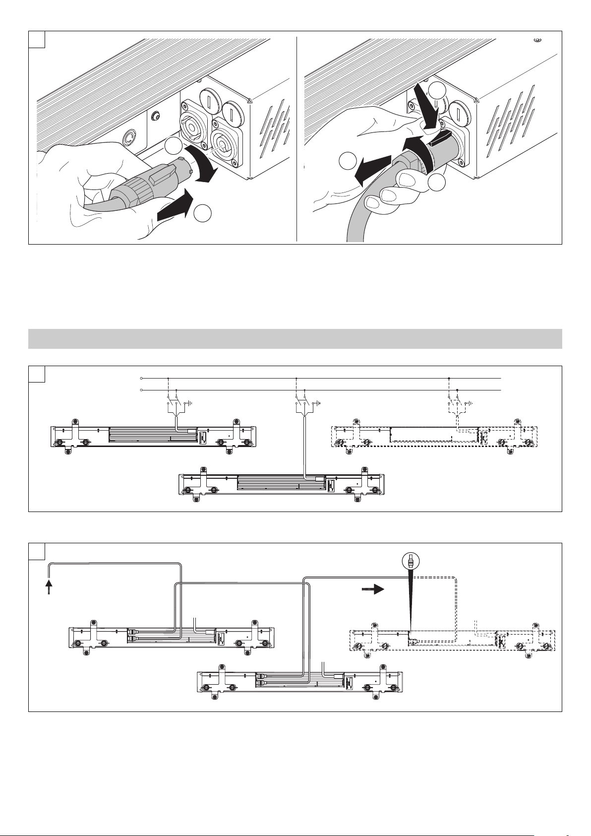
Connecting and disconnecting the power cord - Fig. 5
6
Connections to the power mains - Fig. 6
Power Supply
7
CONTROL PANEL
Connections to the control signal line (DMX) - Fig. 7
Use a cable conforming to specifications EIA RS-485: 2-pole twisted, shielded, 120Ω characteristic impedance, 22-24 AWG, low capacity. Do not use
microphone cable or other cable with characteristics differing from those specified. End connections must be made using XLR type 3-pin male/female
connectors. A terminating plug must be inserted on the last projector with a resistance of 120 (minimum 1/4 W) between terminals 2 and 3.
IMPORTANT: The wires must not make contact with each other or with the metal casing of the connectors. The casing must be connected to the shield
braid and pin 1 of the connectors.
SHOW BATTEN 100
5
Continued
➔
Page 6
8
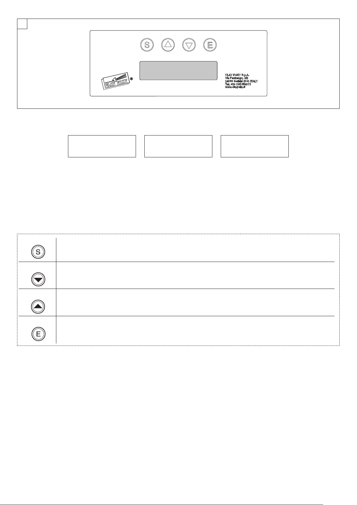
Switching on the projector - Fig. 8
The projector immediately turns on when the power cord is plugged.
Clay Paky SHOW BATTEN 100 Address xxx
SHOW BATTEN 100 Software release x.x x xxxxx ??? *
The control panel (Figure 8) has a display and buttons for complete programming and management of the projector menu.
The display can be in one of two conditions: idle status and settings status. When idle, the projector DMX address is displayed.
If no button is pressed after a wait period (about 60 seconds) when in menu settings status, the display automatically returns to idle status. It should
be noted that when this condition occurs, any modified value that has not yet been confirmed with the
key will be cancelled.
A
Display symbology
Button functions – Menu SET
SELECT
DOWN
UP
• If pressed in idle status: Cyclically switches between idle status and menu settings.
• If pressed while setting a menu: Moves to an upper level without changing anything (exits the function)
Decreases the value displayed (with auto-repetitions), or passes to the next item on the menu
For quick access to the minimum parameter value, press the UP key while holding down the DOWN key.
Increases the value displayed (with auto-repetitions), or passes to the previous item on the menu
For quick access to the maximum parameter value, press the DOWN key while holding down the UP key.
* see pag. 7
ENTER
SHOW BATTEN 100
Confirms the displayed value or activates the displayed function or opens the next menu.
6
Page 7

Main Menu Level 1 Level 2 Level 3 Choices / Values
SET UP
DMX Address
Standard Address 001 - 503
Extended Address 001 - 463
Channel Mode
Standard
Extended
Art-net Interface
Control Protocol
Disabled
Net IP 2.x.x.x.
Net IP 10.x.x.x.
DHCP
Repeat on DMX On / Off
Universe
Standard Universe 000 - 255
Extended Universe 016 - 031
Network Safety On / Off
OPTIONS
Tilt
Invert. Tilt On / Off
Pos Sensor On / Off
Display
Backlight On / Off
Contrast 0 - 10
INFORMATION
System Version
Appl release
Boot release
Fixture Hours
Total Hours
Partial Hours
LED Hours
Total Hours
Partial Hours
LED Temperature
Temperature
Max Temperature
DMX Monitor
Red
000 - 255
Green
000 - 255
Blue
000 - 255
White
000 - 255
CTO
000 - 255
Dimmer
000 - 255
Stop-Strobe
000 - 255
Preset Colours
000 - 255
Zoom
000 - 255
Tilt
000 - 255
Tilt Sensor
Network parameters
IP Address
Network Mask
MAC Address
ENU SETTING
M
SHOW BATTEN 100
7
Continue
➔
Page 8

Main Menu Level 1 Level 2 Level 3 Choices / Values
MANUAL
C
O
NTROL
Red
000 - 255
Green
000 - 255
B
lue
0
00 - 255
White
000 - 255
CTO
000 - 255
Dimmer
000 - 255
Stop-Strobe
000 - 255
Preset Colours
000 - 255
Zoom
000 - 255
Tilt
000 - 255
TEST
n.a
n.a
ADVANCED
Access Code 1234
Firmware uploader
Appl. upload
Boot. upload
Tilt Cal
Reset
SHOW BATTEN 100
8
Page 9

S
ET UP MENU
SET UP - DMX ADDRESS
U
se to set the DMX address to be assigned to the projector according to the type of preset Channel Mode:
•
Standard Address: a DMX address between 1 and 503 can be selected.
• Extended Address: a DMX address between 1 and 463 can be selected.
P
LEASE NOTE: If there is no DMX input signal, the projector address flashes.
SET UP - CHANNEL MODE
Use to set the projector operating mode selecting one of the following:
• Standard: maximum 10 DMX channels occupied.
• Extended: maximum 50 DMX channels occupied.
SET UP - ARTNET INTERFACE - CONTROL PROTOCOL
Use to set the Artnet Control Protocol selecting one of the 4 options available:
• Disabled: Control protocol disabled.
• Net IP 2.x.x.x.: Import the Artnet network belonged to.
• Net IP 10.x.x.x.: Set the alternative Artnet network belonged to.
• DHCP: IP addresses assigned by DHCP server.
SET UP - ARTNET INTERFACE – REPEAT ON DMX
Use to turn the Repeat on DMX function ON or OFF. When ON, the DMX flow set via Artnet is repeated on
DMX cable.
SET UP - ARTNET INTERFACE – UNIVERSE
Use to set the DMX Universe to be assigned to the projector according to the type of set Channel Mode:
• Standard Mode: a DMX universe between 0 and 255 can be selected.
• Extended Mode: a DMX universe between 0 and 15 can be selected.
PLEASE NOTE: If there is no incoming Artnet signal, the projector universe flashes ( Euni=Extended Universe
/ Suni=Standard Universe).
SET UP - ARTNET INTERFACE – NETWORK SAFETY
Use to turn the Network Safety function ON or OFF.
When the Network Safety function is on, if projectors are connected via Ethernet cable in "daisy chain", the
CPU is battery powered and the Artnet signal is not interrupted but propagated when a projector is off.
SHOW BATTEN 100
9
Page 10

OPTIONS MENU
OPTIONS - TILT – INV. TILT
Use to switch the Tilt inversion movement (ON) or (OFF) .
OPTIONS - TILT – POS SENS
Use to switch the restore Tilt position through encoder (ON) or (OFF) if steps are lost accidentally.
OPTIONS - DISPLAY – BACKLIGHT
Turning Backlight function OFF turns off display backlight after 60 seconds of disuse. Press any key to turn
back on. Select (ON) to disable this option.
OPTIONS - DISPLAY – CONTRAST
Use the Contrast option to set display contrast between 0 (maximum display brightness) and 10 (minimum
display brightness).
SHOW BATTEN 100
10
Page 11

INFORMATION MENU
I
NFORMATION MENU – SYSTEM VERSION
Use to view the Appliance release (Application firmware) and Boot release (Security software) firmware
versions loaded in the CPU.
INFORMATION MENU – FIXTURE HOURS
Use to view total projector operating hours from manufacture to date (Total Hours) or operating hours since
the last user reset (Partial Hours).
To reset Partial Hours, press UP and DOWN together for 5 seconds till “Rst?” appears; then press “Enter” to
reset.
INFORMATION MENU – LED HOURS
Use to view total LED operating hours from manufacture to date (Total Hours) or operating hours since the
last user reset (Partial Hours).
To reset Partial Hours, press UP and DOWN together for 5 seconds till “Rst?” appears; then press “Enter” to
reset.
INFORMATION MENU – LED TEMPERATURE
Use to view real-time LED working temperature (Temperature) or maximum LED temperature from last user
reset (Max Temperature).
To reset Maximum Temperature, press UP and DOWN together for 5 seconds till “Rst?” appears; then press
“Enter” to reset.
INFORMATION MENU – DMX MONITOR
Use to view the DMX input level in bits for each projector channel (value between 0 and 255 bits).
INFORMATION MENU – TILT SENSOR
Use to view a projector Tilt position level (value between nn and nn).
INFORMATION MENU – NETWORK PARAMETERS
Allows the "Network" parameters of the projector to be displayed or:
• IP Adress: Internet Protocol address (2 projectors must not have the same IP address)
• IPmask: 255.0.0.0.
• MAC address: Media Access Control (projector’s Ethernet Address).
SHOW BATTEN 100
11
Page 12

M
ANUAL CONTROL MENU
Use to set a projector control panel channel level to manually control each effect without the need of a DMX
i
nput signal (values between 0 and 255 bits).
TEST MENU
Use to check correct effect operations, activating preset projector memory movements.
ADVANCED MENU
Enter access code 1234 to open the Advanced menu (only recommended for expert users).
ADVANCED MENU – FIRMWARE UPLOADER
Use to transfer software from one projector to all the others connected to it selecting between Appl. upload
and Boot upload.
ADVANCED MENU – TILT CAL
Use to recalibrate Tilt position with any problems.
ADVANCED MENU – RESET
Use to reset the projector CPU with any problems.
ERROR LIST
Error Identifier Description
W04 BAT_ALERT Battery guard voltage Display warning
W12 LED_MAX_TEMP
Board maximum temperature reached LED current derating,
Display warning
E13 LED_OVER_TEMP
Board over temperature after derating Display warning, Stop
working, LED power off
E33 INIT_ERROR Startup procedure errors Display warning
W34 FW_UPLOADING
Firmware uploading in progress Display progress status, current
image still running
W35 FW_UPLOADED
Firmware uploading terminated with success Display new
version, new image runs after fixture restart
W36 FW_UPLOAD_ERR
Firmware uploading terminated without success Display
warning, current image still running
W37 FW_BAD_CRC
Firmware uploading terminated with CRC error Display warning,
current image still running
E38 FW_CORRUPTED Firmware image corrupted Display warning, run backup image
W49 SENS_CAL_FAIL Hall Sensor error
These errrors can be shown on the display, the description on this list, can help the user to identify the faulty.
SHOW BATTEN 100
12
Page 13

1
2 Fuses
6.3x32mm 2A-T
(p/n 030472)
9
AINTENANCE
M
Fuses replacing - Fig. 9
Each Show Batten has 2 fuses associated with the main power cord connection.
SHOW BATTEN 100
13
Continue
➔
Page 14

10
Parts requiring frequent cleaning.
Periodic cleaning - Fig. 10
To ensure optimal operation and performance for a long time it is essential to periodically clean the parts subject to dust and grease deposits. The
frequency with which the following operations are to be carried out depends on various factors such as wear and the work environment quality (air
humidity, dust, salinity, etc.). To remove dirt from external parts, use a soft cloth dampened with any liquid glass cleaning detergent.
It is recommended that the projector undergoes an annual service by a qualified technician for special maintenance involving at least the following
operations:
• General cleaning of internal parts.
• General visual check of internal parts, cabling, mechanical parts, etc.
• Electrical, photometric and functional checks; eventual repairs.
Cleaning transparent cover
Only use neutral soap and water to clean the transparent cover then dry it carefully with a soft, non-abrasive cloth. (WARNING: the use of alcohol or
any other detergent could damage the transparent cover.
SHOW BATTEN 100
14
Page 15

226
(8.90")
170
(6.69")
100
(3.94")
186
(7.32")
1000
(39.37")
ECHNICAL DATA
T
Source
10x15W LED RGBW Ostar (OSRAM)
Led pilot power
150W
Optics
Electronically controlled optic zoom
LED color temperature
000K
6
Head adjustment
±120°
Cooling
Forced ventilation with axial fans
User interface
• LCD display 2 lines with 16 characters each,
backlit LED, white on black
• 4 membrane buttons
Connections
• AC power input/output: Neutrik PowerCon
• DMX data in/out: 5-pin locking XLR
• Ethernet in/out with ART-net protocol
External power
full range 100-240V 50-60Hz,
PowerCon connector
Input Power
170 VA
•
• Max 1700VA connecting Max 10 units
Body
• Body extruded in black anodized aluminium
• 2 carrying handles
• 4 non-slip rubber feet
Fittings
4 fast-look holes for omega hook-up
Safety
Eyebolts for safety cables
Weight
9 Kg
Protection rating
IP20
Working position
Works in any position
CE Marking
omplies with the following European Directives
C
- 2006/95/EC (LVD)
- 2004/108/EC (EMC)
- 2011/65/EU (RoHS).
THE PROJECTOR WILL NOT SWITCH ON
THE PROJECTOR WILL NOT SWITCH ON
DEFECTIVE PROJECTION
REDUCED LUMINOSITY
No power supply.
LED burnt out or defective.
Signal transmission cable faulty or disconnected.
Incorrect addressing.
Fault in the electronic circuits.
Optic fault.
Dust or grease deposits.
SHOW BATTEN 100
CAUSE AND SOLUTION OF PROBLEMS
POSSIBLE CAUSES
TROUBLE
CHECKS AND REMEDIES
Check the power supply voltage.
Call an authorised technician.
Replace the cables.
Check addresses (see instructions).
Call an authorised technician.
Call an authorised technician.
Clean (see instructions).
15
Page 16

CHANNEL
CHANNEL MODE
STANDARD EXTENDED
1 RED RED
2 GREEN GREEN
3 BLUE BLUE
4 WHITE WHITE
5 CTO CTO
6 DIMMER DIMMER
7 STROBE STROBE
8 MACRO COLOUR MACRO COLOUR
9 ZOOM ZOOM
10 TILT TILT
11
-
RED LED 1
12
-
GREEN LED 1
13
-
BLUE LED 1
14
-
WHITE LED 1
15 - 18
-
R-G-B-W LED 2
19 - 22
-
R-G-B-W LED 3
23 - 26
-
R-G-B-W LED 4
27 - 30
-
R-G-B-W LED 5
31 - 34
-
R-G-B-W LED 6
35 - 38
-
R-G-B-W LED 7
39 - 42
-
R-G-B-W LED 8
43 - 46
-
R-G-B-W LED 9
47 - 50
-
R-G-B-W LED 10
SHOW BATTEN 100
HANNEL LIST
C
SHOW BATTEN 100
16
Page 17

Channel Mode
DMX
Value
Function
Standard Extended
1 1
RED
0 - 255 Red colour linearly increase from no-light to maximum intensity
2 2
GREEN
0 - 255 Green colour linearly increase from no-light to maximum intensity
3 3
BLUE
0 - 255 Blue colour linearly increase from no-light to maximum intensity
4 4
WHITE
0 - 255 White colour linearly increase from no-light to maximum intensity
5 5
CTO
0 - 9 Unused range
10 - 255 Colour Temperature linearly change
6 6
DIMMER
0 - 255 Light output linearly increase from off to maximum brightness
7 7
STROBE
0 - 3 Light ON
4 - 69
Strobe at linearly variable frequency
from low (1 flash/sec) to high (24 flashes/sec)
70 - 74 Light ON
75 - 140
Pulsation at linearly variable speed
from slow (0.5 flash/sec) to fast (24 flash/sec)
141 - 206
Pulsation at linearly variable speed
from fast (24 flash/sec) to slow (0.5 flash/sec)
207 - 211 Light ON
212 - 224 Random Strobe at low frequency
225 - 237 Random Strobe at medium frequency
238 - 250 Random Strobe at high frequency
251 - 255 Light ON
HANNEL FUNCTIONS
C
SHOW BATTEN 100
17
Continue
➔
Page 18

8 8
MACRO COLOUR
0 - 9 Unused range
10 Red
11 Green
12 Blue
1
3 Cyan
14 Yellow
15 Magenta
16 White 7000K
17 White 3700K
1
8 White 5000K
19 Black
20 – 22 Medium Yellow
23 – 26 Straw Tint
27 – 28 Surprise Peach
29 Fire
30 Medium Amber
31 Gold Amber
32 – 34 Dark Amber
35 – 44 Sunrise Red
45 Light Pink
46 – 48 Medium Pink
49 – 61 Pink Carnation
62 – 67 Light Lavender
68 – 77 Lavender
78 – 88 Sky Blue
89 – 99
Just Blue
100 – 109 Dark Yellow green
110 – 111 Spring Yellow
112 Light Amber
113 Straw
114 Deep Amber
115 – 116 Orange
117 Light Rose
118 English Rose
119 Light Salmon
120 Middle Rose
121 – 122 Dark Pink
123 – 124 Magenta
125 Peacock Blue
126 Med Blue Green
127 Steel Blue
128 Light Blue
129 – 130 Dark Blue
131 – 133 Leaf Green
134 – 135 Dark Green
136 – 137 Mauve
138 – 141 Bright Pink
142 – 144 Medium Blue
145 Deep Golden Amber
146 Pale Lavender
147 – 148 Special lavender
149 – 150 Primary Green
151 – 156 Bright Blue
157 – 161 Apricot
162 – 167 Pale Gold
168 – 171 Deep Orange
172 – 173 Bastard Amber
174 Flame Red
175 – 178 Daylight Blue
179 Lilac Tint
180 – 183 Deep Lavender
184 – 190 Dark Steel Blue
191 – 206 Congo Blue
207 Alice Blue
208 Dirty White
209 - 255 White
SHOW BATTEN 100
18
Page 19

9 9
ZOOM
0 - 255 Zoom linearly moves from narrow to wide beam
10 10
TILT
0 - 255 Moving batten linearly tilts from -120° to +120°
-
11
RED LED 1
0 - 255 Brightness linearly increase from off to maximum value
-
12
GREEN LED 1
0 - 255 Brightness linearly increase from off to maximum value
-
13
BLUE LED 1
0 - 255 Brightness linearly increase from off to maximum value
-
14
WHITE LED 1
0 - 255 Brightness linearly increase from off to maximum value
-
15
RED LED 2
0 - 255 Brightness linearly increase from off to maximum value
-
16
GREEN LED 2
0 - 255 Brightness linearly increase from off to maximum value
-
17
BLUE LED 2
0 - 255 Brightness linearly increase from off to maximum value
-
18
WHITE LED 2
0 - 255 Brightness linearly increase from off to maximum value
- 19 - 22
RED - GREEN - BLUE - WHITE LED 3
0 - 255 Brightness linearly increase from off to maximum value
- 23 - 26
RED - GREEN - BLUE - WHITE LED 4
0 - 255 Brightness linearly increase from off to maximum value
- 27 - 30
RED - GREEN - BLUE - WHITE LED 5
0 - 255 Brightness linearly increase from off to maximum value
- 31 - 34
RED - GREEN - BLUE - WHITE LED 6
0 - 255 Brightness linearly increase from off to maximum value
- 35 - 38
RED - GREEN - BLUE - WHITE LED 7
0 - 255 Brightness linearly increase from off to maximum value
- 39 - 42
RED - GREEN - BLUE - WHITE LED 8
0 - 255 Brightness linearly increase from off to maximum value
- 43 - 46
RED - GREEN - BLUE - WHITE LED 9
0 - 255 Brightness linearly increase from off to maximum value
- 47 - 50
RED - GREEN - BLUE - WHITE LED 10
0 - 255 Brightness linearly increase from off to maximum value
SHOW BATTEN 100
19
Page 20

LED 1
LED 2
LED 3
LED 4
LED 5
LED 6
LED 7
LED 8
LED 9
LED 10
SHOW BATTEN 100
LED reference number for pixel mapping
IST007/001 – EN - Rev - PRELIMINARY 08/14
CLAY PAKY S.p.A. - Via Pastrengo, 3/b - 24068 Seriate (BG) Italy - Tel. +39-035-654311 - Fax +39-035-301876 - www.claypaky.it
 Loading...