

Page 1

Flow
L.P. Low Pressure
Sensing Port
3/8 NPT
2X Raised
Face Dia.
2.00
20” - 24” - 30” - 36”
MODEL
X52E
Orifice Plate Assembly
• Wafer Design
• Fits ANSI 125, 150, 250, 300
• Optional Materials Available
• Easy to use size Selection Chart
The Cla-Val Model X52E Orifice Plate Assembly is typically used with
Cla-Val flow control valves. The orifice plate is an essential component
used to generate a specific, predictable pressure drop in the system.
The X52E uses a wafer design holder which offers a compact lightweight assembly that is easy to install. The X52E has a Chamfered
"Inlet" side so even after installation, correct orientation can be easily
verified.
The orifice plate portion of the assembly is made of 302 stainless steel
with other materials options also available. The plate is machined to a recommended "square edge". The plate holder portion of the assembly is
Ductile Iron standard. Fusion-bonded epoxy coating is an option. The
holder may be made of other materials.
Dimensions
A
Bolt Hole
Size and Number of Bolt Holes
Vary with Pipe Size (See Table)
NOMINAL PIPE SIZE (inches)
Diameter of Flange
Diameter of Raised Face
"A" Dim from CL to top of boss
Diameter of Bolt Circle (B.C.D.)
Number of Bolts
150 Lb.
Radius of Bolt Holes
300 Lb.
*Consult Factory
Diameter of Bolt Circle
Number of Bolts
4" Size Shown
Selecting an orifice plate bore size is made by using charts provided.
We recommend installation of this assembly with the sensing port to the
side of the pipeline to prevent air pockets and obstructions in the sensing line. Installation adjacent to a butterfly valve is not recommended as
the orifice plate assembly may interfere with the opening of this type of
valve.
1.00
Flow
B.C.D.
Flow
A
"A"
1-1/2” thru 18”
1-1/2 2 2-1/2 3 4 6 8 10 12 14 16 18 20 24 30 36
3.63 4.25 5.00 5.75 7.00 9.75 12.00 14.14 16.50 19.00 21.12 23.50 25.62 27.25 30.26 36.26
2.88 3.63 4.13 5.00 6.19 8.50 10.63 12.75 15.00 16.25 18.50 21.00 23.00 23.50 29.25 35.25
2.31 2.62 3.00 3.38 4.00 5.38 6.50 7.62 8.75 10.00 11.06 12.50 13.75 16.00 19.50 22.88
3.88 4.75 5.50 6.00 7.50 9.50 11.75 14.25 17.00 18.75 21.25 22.75 25.00 29.50 36.00 42.75
4 4 4 4 8 8 8 12 12 12 16 16 20 20 28 32
.31 .38 .38 .38 .38 .44 .44 .50 .50 .56 .56 .62 .62 .69 .69 .81
4.50 5.00 5.50 6.63 7.88 10.63 13.00 15.25 17.75 20.25 22.50 24.75 27.00 30.38 CF* CF*
4 8 8 8 8 12 12 16 16 20 20 24 24 20 CF* CF*
L.P. Low Pressure
Sensing Port
1/4 - 18 NPT
2X Raised
Face Dia.
150 LB CONFIGURATION
300 LB CONFIGURATION
Page 2

Sizing An Orifice Plate Bore
1. In determining a bore size, the nominal flow rate (or range of flow) and the pipe size in which the orifice plate assembly will
be installed must be known.
2. Sizing a bore for:
A constant flow rate:
Select the sizing chart that matches pipe size and locate the flow rate under the nominal column which is closest to
required flow; select the corresponding bore size dimension.
Example:
A 6" pipe with a desired constant flow of 700
gpm.
Using the 6" chart, the closest flow in the nominal
column is 670
gpm which has a corresponding bore
size of 3.80".
Bore
Size
4.60 490 1960 1100
4.40 435 1740 980
4.20 380 1520 850
4.00 330 1320 750
3.80 300 1200 670
3.60 265 1060 590
3.40 230 920 520
3.20 200 800 450
3.00 175 700 395
2.80 150 600 340
2.60 130 520 295
2.40 110 440 245
Min. Max. Nominal
A flow range:
Select the sizing chart that matches pipe size and locate required flow range between the minimum and maximum limits of an
orifice bore. Frequently the flow range will fit between more than one bore size. To resolve this, decide the flow rate that
system will be operated at most frequently. Locate the flow which is closest to this under the nominal flow column, and
select the corresponding bore size dimension.
Flow - gpm
6" Valve / Pipe Size
6" Valve / Pipe Size
Example:
A 6" pipe with a flow range of 300-1000 gpm. Using
the 6" chart, more than one bore size can accommodate this range. The most frequent flow rate will
be 500 gpm. Using the nominal flow column, the
closest flow is 520 gpm which has a corresponding
bore size of 3.40"
Bore
Size
4.60 490 1960 1100
4.40 435 1740 980
4.20 380 1520 850
4.00 330 1320 750
3.80 300 1200 670
3.60 265 1060 590
3.40 230 920 520
3.20 200 800 450
3.00 175 700 395
2.80 150 600 340
2.60 130 520 295
2.40 110 440 245
Min. Max. Nominal
Flow - gpm
Orifice Plate Bore Chart
2" Valve / Pipe Size
Bore
Size
1.55 55 220 125
1.50 50 200 11 5
1.40 42 168 95
1.20 29 11 6 65
1.00 19 76 45
.80 12 50 28
1/2
*For 1
" bore information please consult the factory
Min. Max. Nominal
Flow - gpm
21⁄2" Valve / Pipe Size
Bore
Size
1.87 80 330 180
1.60 55 220 120
1.40 40 160 88
1.20 28 11 5 62
1.00 19 80 43
.80 12 50 28
Min. Max. Nominal
Flow - gpm
Page 3

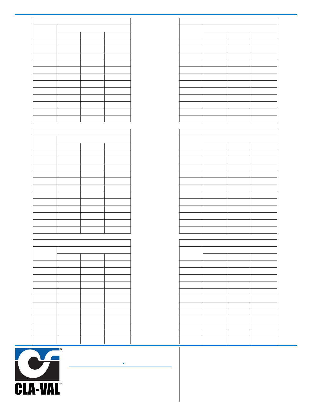
3" Valve / Pipe Size
Bore
Size
2.29 120 480 270
2.20 105 420 240
2.00 84 336 190
1.80 65 260 145
1.60 50 200 11 5
1.40 38 152 86
1.20 28 11 2 62
1.00 19 76 43
Min. Max. Nominal
Flow - gpm
4" Valve / Pipe Size
Bore
Size
3.00 205 820 450
2.80 170 680 390
2.60 140 560 310
2.40 115 460 260
2.20 96 384 215
2.00 78 312 175
1.80 63 252 140
1.60 49 196 11 0
1.40 38 152 84
1.20 28 11 2 62
Min. Max. Nominal
Flow - gpm
6" Valve / Pipe Size
Bore
Size
4.60 490 1960 1100
4.40 435 1740 980
4.20 380 1520 850
4.00 330 1320 750
3.80 300 1200 670
3.60 265 1060 590
3.40 230 920 520
3.20 200 800 450
3.00 175 700 395
2.80 150 600 340
2.60 130 520 295
2.40 110 440 245
Min. Max. Nominal
Flow - gpm
8" Valve / Pipe Size
Bore
Size
6.00 830 3320 1850
5.80 760 3040 1700
5.60 680 2720 1550
5.40 620 2480 1400
5.20 570 2280 1275
5.00 515 2060 1150
4.80 470 1800 1050
4.60 425 1700 950
4.40 385 1540 860
4.20 345 1380 780
4.00 310 1240 700
Min. Max. Nominal
Flow - gpm
10" Valve / Pipe Size
Bore
Size
7.50 1300 5200 2900
7.00 1075 4300 2400
6.50 880 3520 1950
6.00 730 2920 1650
5.50 600 2400 1350
5.00 490 1960 1100
4.50 390 1560 870
4.00 310 1240 690
3.50 235 940 525
3.00 175 700 385
Min. Max. Nominal
Flow - gpm
12" Valve / Pipe Size
Bore
Size
9.00 1850 7400 4200
8.50 1575 6300 3500
8.00 1350 5400 3000
7.50 1150 4600 2600
7.00 980 3920 2200
6.50 840 3360 1875
6.00 700 2800 1575
5.50 580 2320 1300
5.00 480 1920 1075
4.50 385 1540 870
Min. Max. Nominal
Flow - gpm
14" Valve / Pipe Size
Bore
Size
10.00 2350 9400 5200
9.50 2025 8100 4500
9.00 1750 7000 3900
8.50 1500 6000 3400
8.00 1300 5200 2900
7.50 1150 4600 2500
7.00 960 3840 2150
6.50 820 3280 1850
6.00 700 2800 1550
5.50 585 2340 1300
5.00 480 1920 1075
4.50 385 1540 860
Min. Max. Nominal
Flow - gpm
Page 4
16" Valve / Pipe Size
C
Bore
Size
11.50 3100 12400 7000
11.00 2700 10800 6100
10.50 2400 9600 5400
10.00 2100 8400 4700
9.50 1850 7400 4200
9.00 1650 6600 3650
8.50 1450 5800 3250
8.00 1250 5000 2850
7.50 1100 4400 2450
7.00 950 3800 2150
6.50 810 3240 1800
6.00 700 2800 1550
Min. Max. Nominal
Flow - gpm
24" Valve / Pipe Size
Bore
Size
17.00 8500 25500 15000
16.00 7500 21500 12500
15.00 6100 18400 10500
14.50 5700 17000 9800
14.00 5200 15600 9000
13.50 4800 14400 8300
13.00 4400 13200 7600
12.50 4000 12100 7000
12.00 3700 11100 6400
11.50 3400 10100 5800
11.00 3100 9200 5300
10.50 2800 8300 4800
Min. Max. Nominal
Flow - gpm
18" Valve / Pipe Size
Bore
Size
13.00 5200 15500 9000
12.00 4100 12300 7100
11.50 3700 11000 6400
11.00 3300 9850 5700
10.50 2950 8800 5100
10.00 2600 7850 4550
9.50 2350 6200 3600
9.00 2100 6200 3600
8.50 18500 5500 3200
8.00 1650 4850 2800
7.50 1400 4250 2450
7.00 1250 3650 2100
Min. Max. Nominal
Flow - gpm
20" Valve / Pipe Size
Bore
Size
14.00 6000 18000 10500
13.50 5300 16000 9500
13.00 4800 14500 8500
12.50 4300 12900 7500
12.00 3900 11700 6700
11.50 3400 10500 6100
11.00 3200 9500 5500
10.50 2900 8600 5000
10.00 2600 7700 4500
9.50 2300 6100 3600
9.00 2000 6100 3600
8.50 18000 5400 3200
Min. Max. Nominal
Flow - gpm
30" Valve / Pipe Size
Bore
Size
22.00 14500 44000 25000
21.00 12000 35000 20500
20.00 10500 31000 19000
19.00 9500 28000 16000
18.00 8500 24500 14500
17.00 7500 22000 12500
16.00 6500 19000 11400
15.00 5600 17000 9900
14.00 4900 14600 8500
13.00 4200 12600 7300
12.00 3700 11000 6400
11.00 3000 8500 5000
Min. Max. Nominal
Flow - gpm
36" Valve / Pipe Size
Bore
Size
26.00 20000 60000 35000
24.00 16000 48500 28000
22.00 13000 39000 22500
21.00 12000 35000 20500
20.00 10500 31000 18000
19.00 9500 28000 16000
18.00 8500 24500 14500
17.00 7500 22000 12500
16.00 6500 19300 11000
15.00 5600 16900 9800
14.00 4900 14600 8500
13.00 4200 12600 7300
Min. Max. Nominal
Flow - gpm
E-X52E (R-9/2011)
LA-VAL
PO Box 1325 Newport Beach CA 92659-0325
Phone: 949-722-4800 Fax: 949-548-5441
CLA-VAL CANADA CLA-VAL EUROPE
4687 Christie Drive
Beamsville, Ontario
Canada L0R 1B4
Phone: 905-563-4963
Fax: 905-563-4040
©COPYRIGHT CLA-VAL 2011 Printed in USA
Specifications subject to change without notice.
Chemin dés Mesanges 1
CH-1032 Romanel/
Lausanne, Switzerland
Phone: 41-21-643-15-55
Fax: 41-21-643-15-50
www.cla-val.com
Represented By:
 Loading...