

Page 1
INSTALLATION / OPERATION / MAINTENANCE
DESCRIPTION
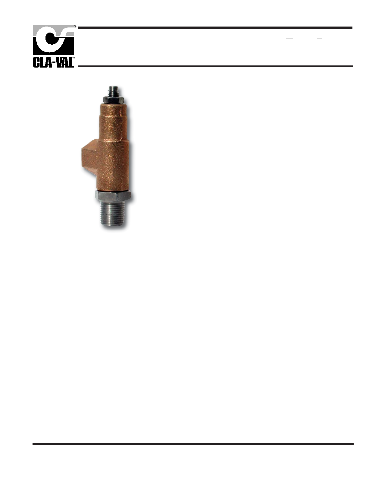
The Cla-Val Model CV Flow Control is a simply-designed,
spring-loaded check valve. Rate of flow is full flow in one direction and restricted in other direction. Flow is adjustable in the
restricted direction. It is intended for use in conjunction with a
pilot control system on a Cla-Val Automatic Control Valve.
OPERATION
The CV Flow Control permits full flow from port A to B, and
restricted flow in the reverse direction. Flow from port A to B
lifts the disc from seat, permitting full flow. Flow in the reverse
direction seats the disc, causing fluid to pass through the clearance between the stem and the disc. This clearance can be
increased, thereby increasing the restricted flow, by screwing
the stem out, or counter-clockwise. Turning the stem in, or
clockwise reduces the clearance between the stem and the
disc, thereby reducing the restricted flow.’
MODEL
CV
Flow Control
DISASSEMBLY
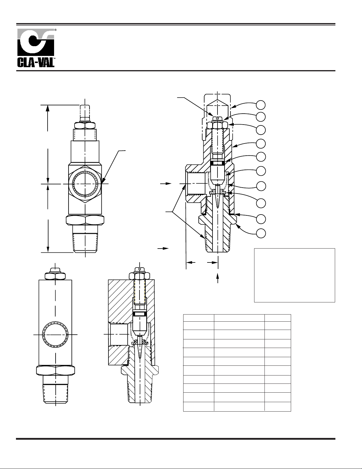
Follow the sequence of the item numbers assigned to the
parts in the cross sectional illustration for recommended
order of disassembly.
Use a scriber, or similar sharp-pointed tool to remove O-ring
from the stem.
INSPECTION
Inspect all threads for damage or evidence of crossthreading. Check mating surface of seat and valve disc for
excessive scoring or embedded foreign particles. Check
spring for visible distortion, cracks and breaks. Inspect all
parts for damage, corrosion and cleanliness.
CLEANING
After disassembly and inspection, cleaning of the parts can
begin. Water service usually will produce mineral or lime
deposits on metal parts in contact with water. These
deposits can be cleaned by dipping the parts in a 5-percent
muriatic acid solution just long enough for deposits to dissolve. This will remove most of the common types of
deposits. Caution: use extreme care when handling
acid. If the deposit is not removed by acid, then a fine grit
(400) wet or dry sandpaper can be used with water. Rinse
parts in water before handling. An appropriate solvent can
clean parts used in fueling service. Dry with compressed air
or a clean, lint-free cloth. Protect from damage and dust
until reassembled.
REPAIR AND REPLACEMENT
Minor nicks and scratches may be polished out using a fine
grade of emery or crocus cloth; replace parts if scratches
cannot be removed.
Replace O-ring packing and gasket each time CV Flow
Control is overhauled.
Replace all parts which are defective. Replace any parts
which create the slightest doubt that they will not afford completely satisfactory operation. Use Inspection steps as a
guide.
INSTALLATION
Install the CV Flow Control as shown in the valve schematic
All connections must be tight to prevent leakage.
P.O. Box 1325 • Newport Beach, CA 92659-0325 • Phone: 949-722-4800 • Fax: 949-548-5441 • E-mail: [email protected] • Website cla-val.com
©
CLA-VAL
Copyright Cla-Val 2009 Printed in USA Specifications subject to change without notice.
REASSEMBLY
Reassembly is the reverse of disassembly; no special tools
are required.
TEST PROCEDURE
No testing of the flow Control is required prior to reassembly
to the pilot control system on Cla-Val Main Valve.
N-CV (R-1/09)
Page 2
2.12
MAX
ADJUSTING STEM
(TURN CLOCKWISE TO
INCREASE RESTRICTION)
STAMP PART NO. ON
SMOOTH SURFACE
RESTRICTED
FLOW
PARTS LIST
CV
3/8" Flow Control
1
7
2
10
9
8
6
1.84
BAR STOCK
CONFIGURATION
3/8 - 18 NPT
5
4
3
When ordering parts,
.85
FREE FLOW
ITEM DESCRIPTION QTY
1 Cap (SS only) 1
2 Nut, Jam 1
3 Seat 1
4 Gasket 1
5 Disc 1
6 Spring 1
7 Ring, Retaining 1
8 Stem 1
9 O-Ring 1
10 Housing 1
please specify:
• Number Stamped on Side
• Description (CV Flow Control)
• Part Description
• Material
CLA-VAL
P.O. Box 1325 • Newport Beach, CA 92659-0325 • Phone: 949-722-4800 • Fax: 949-548-5441 • E-mail: [email protected] • Website cla-val.com
©
Copyright Cla-Val 2009 Printed in USA Specifications subject to change without notice.
PL-CV (R-1/09)
 Loading...