

Page 1
X144 e-FlowMeter
Installation
Maintenance
Operation
Page 2
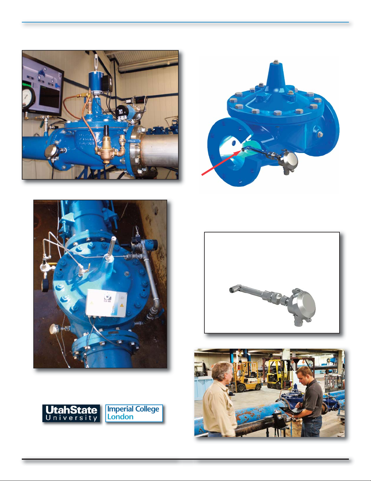
Plug-and-Play Metering: Cla-Val X144 e-FlowMeter
flow direction
Proven Technology from
the Industry Leader
A view inside the X144 e-FlowMeter
Log-on to
www.cla-val.com and click Electronic
Products to learn more about our
complete line of e-products.
Laboratory Tested • Field Proven • Performance Assured
Page 3

X144 e-FlowMeter Installation,
Operation and Maintenance
Table of Contents
Topic
Introduction
Section1: System Components and How They Work:
1.1 - Theory of Operation
1.2 - Supplied Parts List
1.3 - Non-Supplied Parts List
Section 2: Installation of the X144 e-FlowMeter
2.1 - Installation Location Recommendations
2.2 - Materials Required for Installation
2.3 - Mounting the X144 e-FlowMeter
2.4 - Step-By-Step Instructions: Mechanical Installation
2.5 - Step-By-Step Instructions: Electrical Installation
2.6 - Wiring Diagram
Section 3: X144 e-FlowMeter Operation
3.1- Starting Operation
3.2 - Stopping Operation/ Removal of the X144 e-FlowMeter
Section 4: Maintenance and Repair
4.1 - Routine Maintenance
4.2 - Cleaning Debris from Measurement Cylinder
4.3 - Dealing with Sensor Tip Damage
Page #
1
2 - 4
2
3
4
5 - 12
5
6
7
8 - 11
12
13 - 14
15 - 17
15
15 - 17
18
18
18
Section 5: Specifications
Table 2: Electrical Specifications
Table 3: Mechanical Specifications
Dimensional Drawing: X144 e-FlowMeter
Table 4: X144 e-FlowMeter Dimensions
Dimensional Drawing/Data: Insertion Tool
Table 5: Insertion Tool Chart
Table 6: Flow Ranges
Table 7: X144 e-FlowMeter Analog Range (4-20mA Scaling):
Factory Settings
Additional Reference:
Quick Start Instructions
Contact Information
www.cla-val.com
19
19
19
20
21
21
21
22
22
23 - 24
Back Cover
Page 4
INTRODUCTION:
X144 e-FlowMeter Installation, Maintenance and Operation
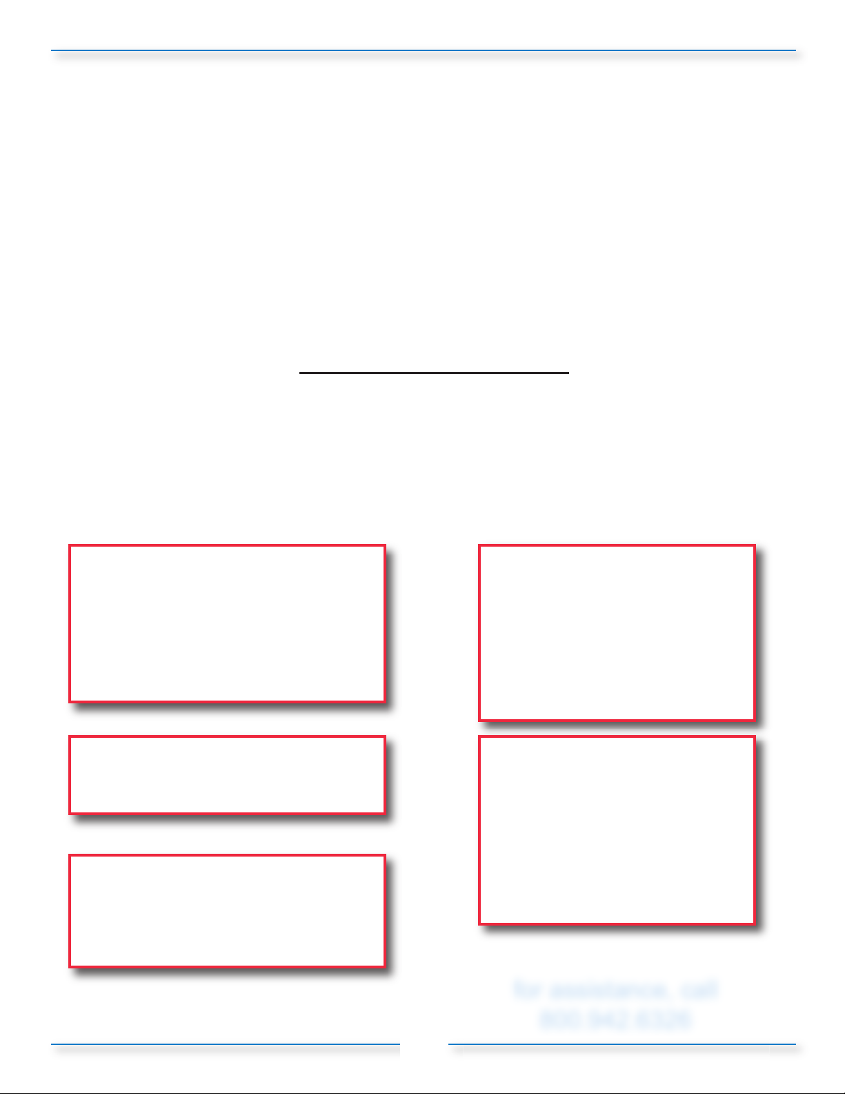
The X144 is an insertion flow meter designed to provide flow information from inside a Cla-Val Control
valve.This innovative device measures flow information using standard Cla-Val control valve bodies at locations
where typical flow meters cannot provide accurate measurements. As opposed to industry standard insertion
flow meters, the X144 e-FlowMeter can be installed directly into the inlet side of a Cla-Val Control Valve,
eliminating the need for costly downtime and pipe work. The X144 can also be inserted in valves at piping
locations not usually permitted for flow measurement, such as directly downstream of a flow disturbance such
as elbows, valves or reducer within just a few pipe diameters (see installation recommendations for conditions.)
This manual will help you install, operate, and maintain the X144 e-FlowMeter.
Important Safety Information
The following safety notices are used in this manual:
• CAUTION: indicates that minor personal injury, product or property damage may occur if
the notice is ignored.
• NOTE: indicates special instructions that are important but are not related to hazards.
Please see examples shown below:
NOTE: The X144 e-FlowMeter may be
installed in inlet tap of either side of the
Cla-Val Automatic Control Valve.
CAUTION: Failure to install the unit
correctly could result in faulty operation
and/or damage to the unit.
CAUTION:
In all cases, installation should be done by
qualified mechanical or electrical
personnel.
CAUTION: BEFORE removing pipe plug,
make sure that the pressure in the valve
has been bled off to prevent injury to
personnel or damage to non-waterproof
equipment.
CAUTION:
Valve in which X144 e-FlowMeters
are installed MUST have upstream
and downstream Isolation Valves to
ensure that the line is locked out and
not under pressure during
installation, maintenance or removal
of the X144 e-FlowMeter.
CAUTION 1: Failure to use the
provided Insertion Tool WILL result
in damage to the e-FlowMeter
CAUTION 2: To avoid injury, isolate
the valve and bleed pressure prior
to removing the e-FlowMeter
for assistance, call
800.942.6326
1
Page 5
SECTION 1: System Components and How They Work
Bluff Body
Sensor
Karman
Vortex
Street
Flow
Direction
Meter Bluff Body
Flow
Direction
Integral Sensor
Flow
Direction
Vortices
Measurement Cylinder
1.1 - Theory of Operation
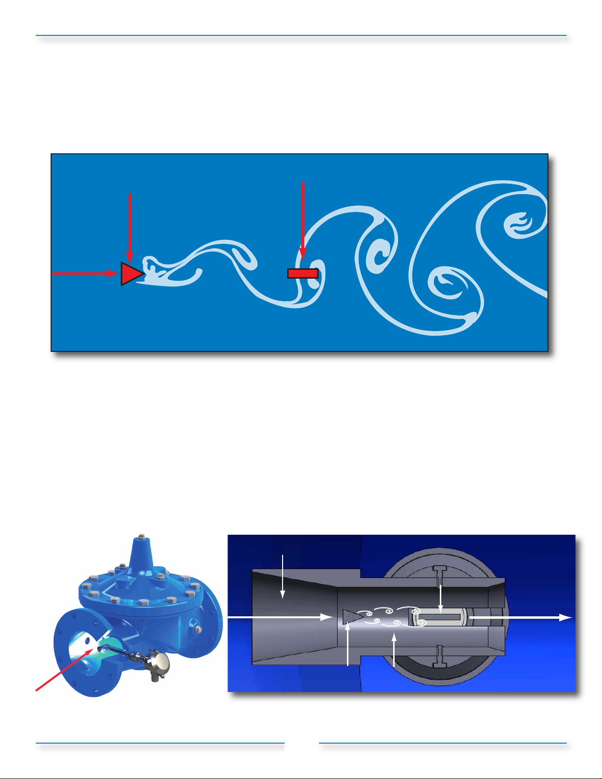
The X144 e-FlowMeter is an insertion vortex flowmeter based on a phenomenon which generates of a
succession of alternating swirls called Karman vortex street (Figure 1-1).
Figure 1-1: Karman Vortex Street
When the fluid meets an obstacle (called a bluff body) which is placed in parallel with the flow of the fluid it
divides the flow and generates small swirls or vortices alternately on both sides downstream of the obstacle.
The generation of the swirls is directly proportional to the speed of the fluid. The detached swirls generate
zones of variable pressure that are detected by the forces acting on a small piezoelectric crystal
encapsulated in the transmitter (Figures 1-2 and 1-3).
The X144 e-FlowMeter employs an innovative feature called the Swivel Measurement Cylinder which allows
for the proper distance between the bluff body and the sensor, while still retaining the capability of being
inserted into a tapping as small as 1/2-inch NPT.
flow direction
Figure 1-2
Figure 1-3
2
Page 6
SECTION 1: System Components and How They Work (continued)
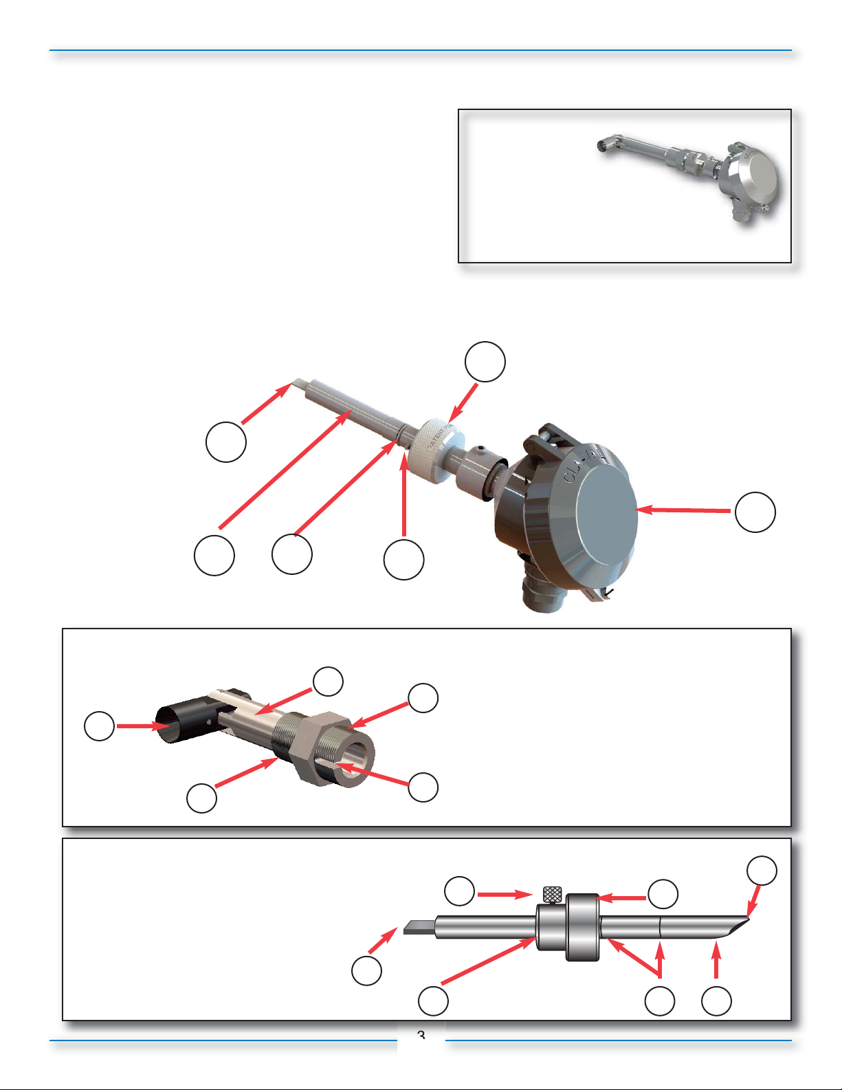
1.2 – Supplied Parts List
X144 Equipment - Supplied by Cla-Val
1) e-FlowMeter with Swivel Threaded Insert
(Figures 1-4 and 1-5)
2) Insertion Tool (Figure 1-6)
3) 20 feet of Electrical Cable (See Section 2.5)
X144 e-FlowMeter Parts
1) IP68 Submersible Electronics Housing 2) Knurled Lock 3) Centering Pin
4) O-Ring 5) Shaft 6) Sensor
Figure 1-4: e-FlowMeter
6
Swivel
Threaded Insert
X144 e-FlowMeter
2
1
5
4
Figure 1-5: e-FlowMeter Swivel Threaded Insert Detail
5
3
Figure 1-6: Insertion Tool Kit
Insertion Tool Kit Parts
1) Bevel
2) Tool
3) Score Marks
4) Thumb Set Screw
5) Tool Lock
6) Flat Tipped End
7) Locking Collar
3
4
1
2
Swivel Threaded Insert Parts
1) Straight Threads
2) Centering Groove
3) Tapered Threads
4) Sleeve
5) Swivel Measurement Cylinder
1
4
7
6
5
3
2
3
Page 7
SECTION 1: System Components and How They Work (continued)
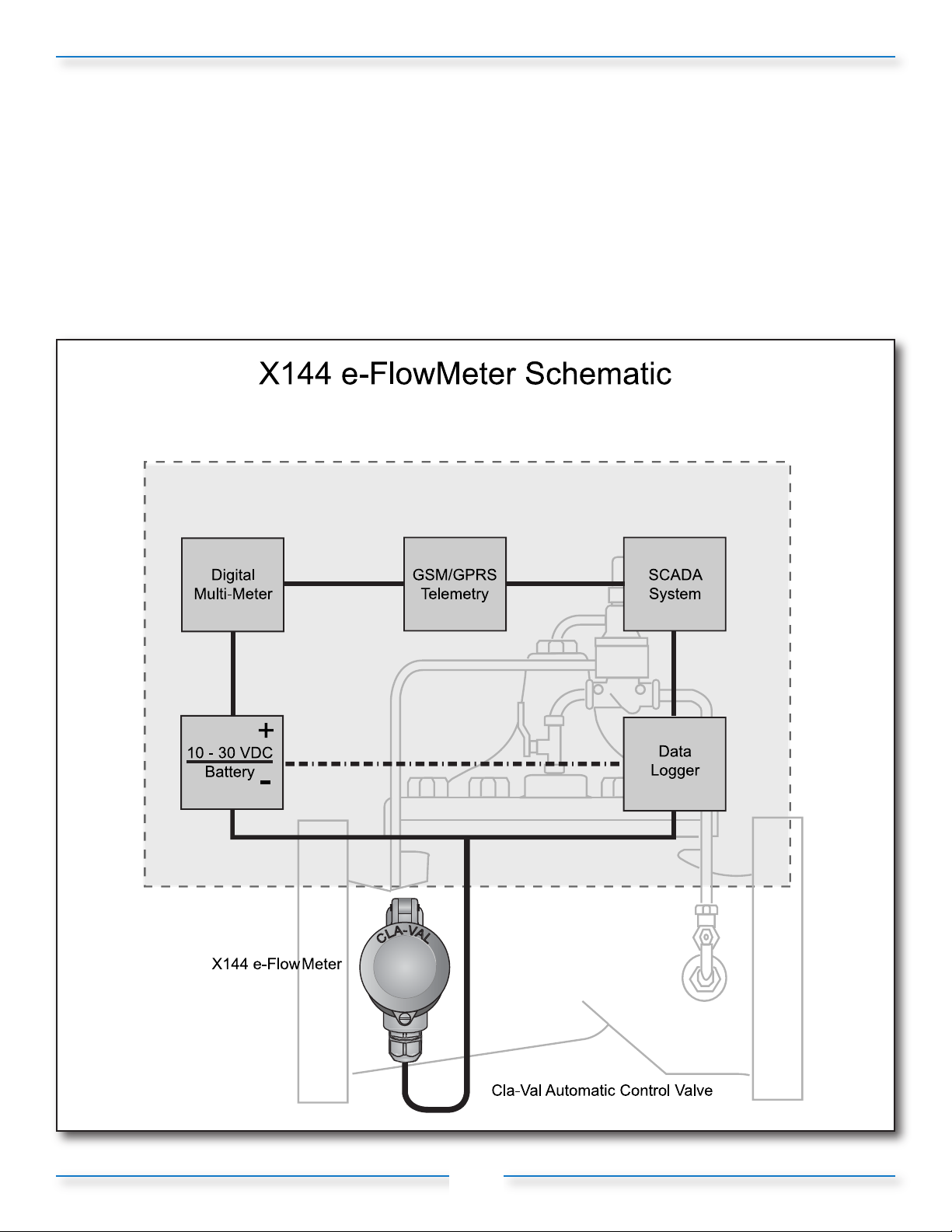
with optional equipment to pair with
the X144 e-FlowMeter™ using 4-20mA Output
1.3 – Non-Supplied Parts List
The following parts are necessary for installation and operation but not included with the e-FlowMeter:
• Cla-Val Automatic Control valve in which to insert the e-FlowMeter - Globe-Style only, 2-1/2 - 16”.
• Power supply
- 12/24 VDC, 0.7 Watts minimum
- Can be powered with batteries or AC/DC Converter
• Power supply/battery housing
• Housing mounting hardware
4
Page 8
Section 2: Installation of the X144 e-FlowMeter
2.1 - Installation Locations:
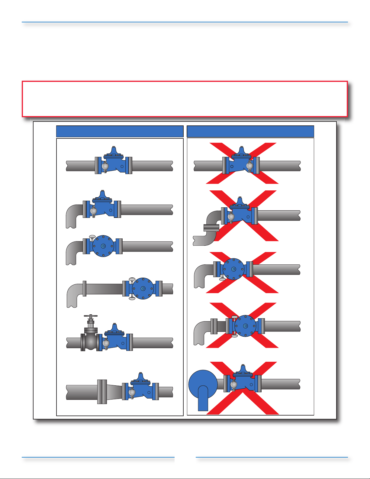
For optimum performance, it is recommended that the valve in which the X144 e-FlowMeter is installed be
located as shown in the “Optimum Installations” illustration below, Figure 2-1.
CAUTION: Valve in which X144 e-FlowMeters are installed MUST have upstream and downstream Isolation
Valves to ensure that the line is locked out and under pressure during installation, maintenance or removal of
the X144 e-FlowMeter.
Optimum Installations
In Inlet Tapping
(vertical rise)
Outside Elbow
> 5 Pipe Diameters
Either Inlet Tapping
CLA-VAL
CLA-VAL
Downstream
of an Elbow
(top view)
(top view)
Unacceptable Installations
In Outlet Tapping
CLA-VAL
Downstream of
Double Elbow
CLA-VAL
Inside of
an Elbow
(top view)
1 to 5 Pipe
Diameters
CLA-VAL
Isolation Valve MUST be Wide Open or
5 pipe diameters upstream
CLA-VAL
Pipe Reducer Upstream
pump
pump
Outside
or Inside
CLA-VAL
Note: Do not use with 40 Series Rate-of-Flow Controllers with orifice on inlet
Figure 2-1: Installation Guidelines
5
(top view)
On Discharge
of a Pump
Page 9
Section 2: Installation of the X144 e-FlowMeter (continued)
2.2 - Materials Required for Installation
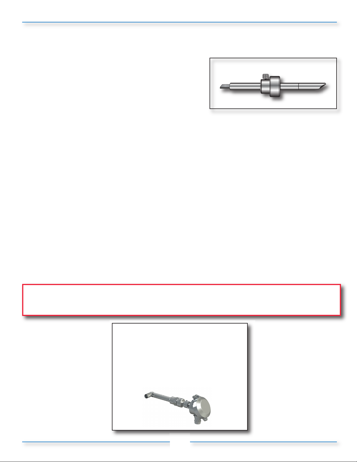
Insertion tool
• Tool allows the proper installation and alignment of the
bluff body to be parallel to upstream flow, (Figure 1-5).
Figure 1-5: Insertion Tool
Power Supply
• 12/24 VDC, 0.7 Watts minimum. If more than one piece of equipment will be connected to
this power supply, you must verify that the power supply is large enough to handle all the power needs of
the entire system, not just the X144 e-FlowMeter.
• You will also need the appropriate equipment to connect the X144 to each the power supply. See your
local electrical specifications to determine the appropriate wire and connection hardware.
Pipe and Fittings Mounting Hardware
• The X144 connects directly into the control valve on an inlet port and the size of the thread is dependent
on the specific valve size for which it it has been calibrated - no additional fittings are required.
Cabling
• The X144 has 30 feet cable supplied and attached as a factory standard. If additional lengths of cable are
needed, the connections should be made with #22 AWG or larger cable and may need to be shielded in
some environments where high electrical noise may exist. If using shielded cable, one end of the shielding
should be connected to an earth ground, such as a piping system fitting, etc.
CAUTION:
• In all cases, installation should be done by qualified mechanical or electrical personnel.
Log-on to
www.cla-val.com
and click on the
X144 e-FlowMeter icon to see
the installation video
6
Page 10
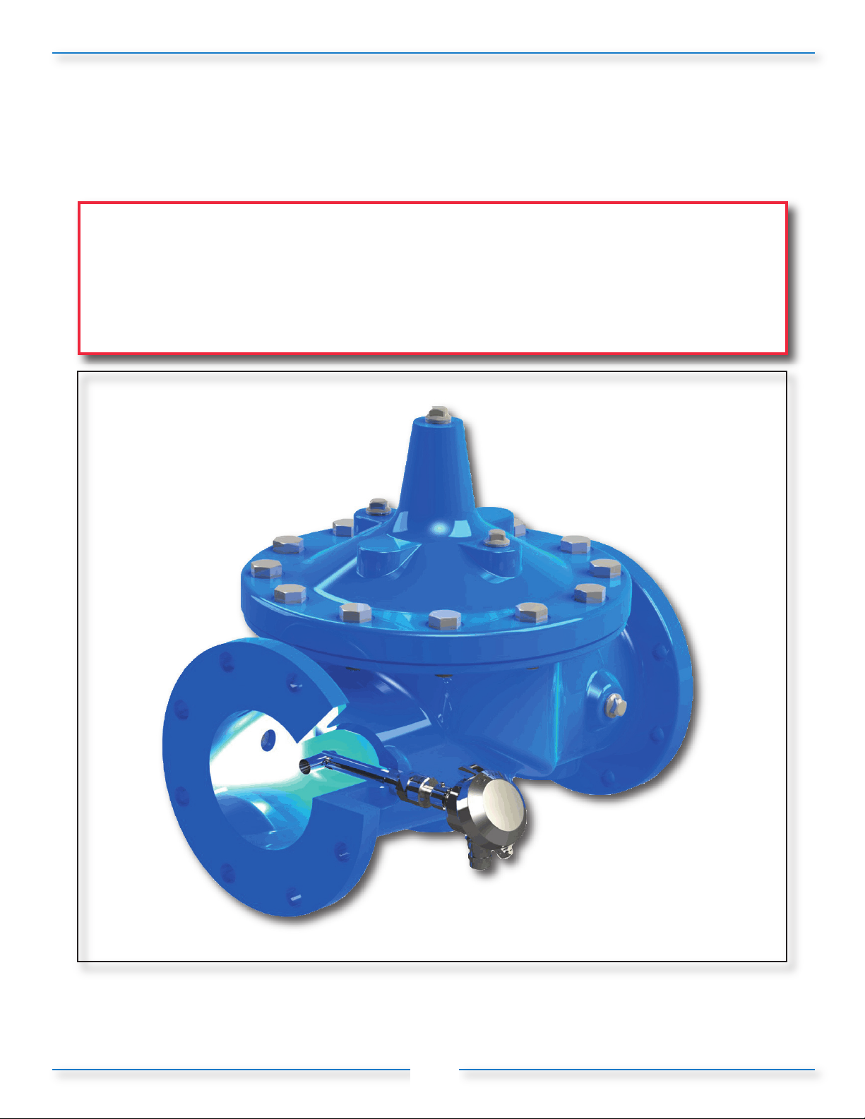
Section 2: Installation of the X144 e-FlowMeter (continued)
2.3 - Mounting the X144 e-FlowMeter
Mount the X144 e-FlowMeter in a proper orientation as shown in Figure 2-2.
NOTE: The X144 e-FlowMeter may be installed in inlet tap of either side of the
Cla-Val Automatic Control Valve.
CAUTION: Failure to install the unit correctly could result in faulty operation and/or damage
to the unit.
Figure 2-2: X144 e-FlowMeter correctly installed in a Cla-Val Control Valve
7
Page 11
Section 2: Installation of the X144 e-FlowMeter (continued)
2.4 - Step-by-Step Instructions: Mechanical Installation
CAUTION: BEFORE removing pipe plug, make sure that the pressure in the valve has been bled
off to prevent injury to personnel or damage to non-waterproof equipment
1) Isolate valve/pipe from pressure and flow.
2) Remove pipe plug on INLET boss of valve.
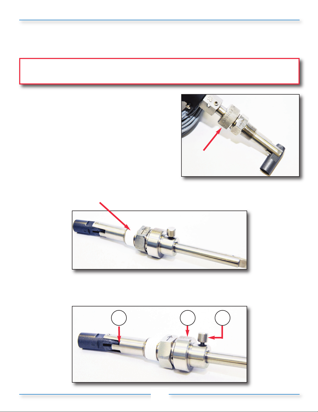
3) Remove sensor/head unit from threaded pipe insert
by unscrewing the knurled lock and sliding the sensor
out of the threaded insert (Figure 2-3).
Set aside sensor head, making sure to protect the
sensor tip
Figure 2-3
4) Apply Teflon®thread tape and/or pipe thread compound to tapered threads on pipe insert,
shown below (Figure 2-4):
Figure 2-4
5) Straighten the Measurement Cylinder by hand to create a slight angle (Figure 2-5); Tighten the
locking collar on the straight threads of the insert (2); and tighten the thumb
set screw (3); to maintain the slight angle of the Measurement Cylinder.
1 2
3
Figure 2-5
8
Page 12
Section 2: Installation of the X144 e-FlowMeter (continued)
2.4 - Step-by-Step Instructions Mechanical Installation
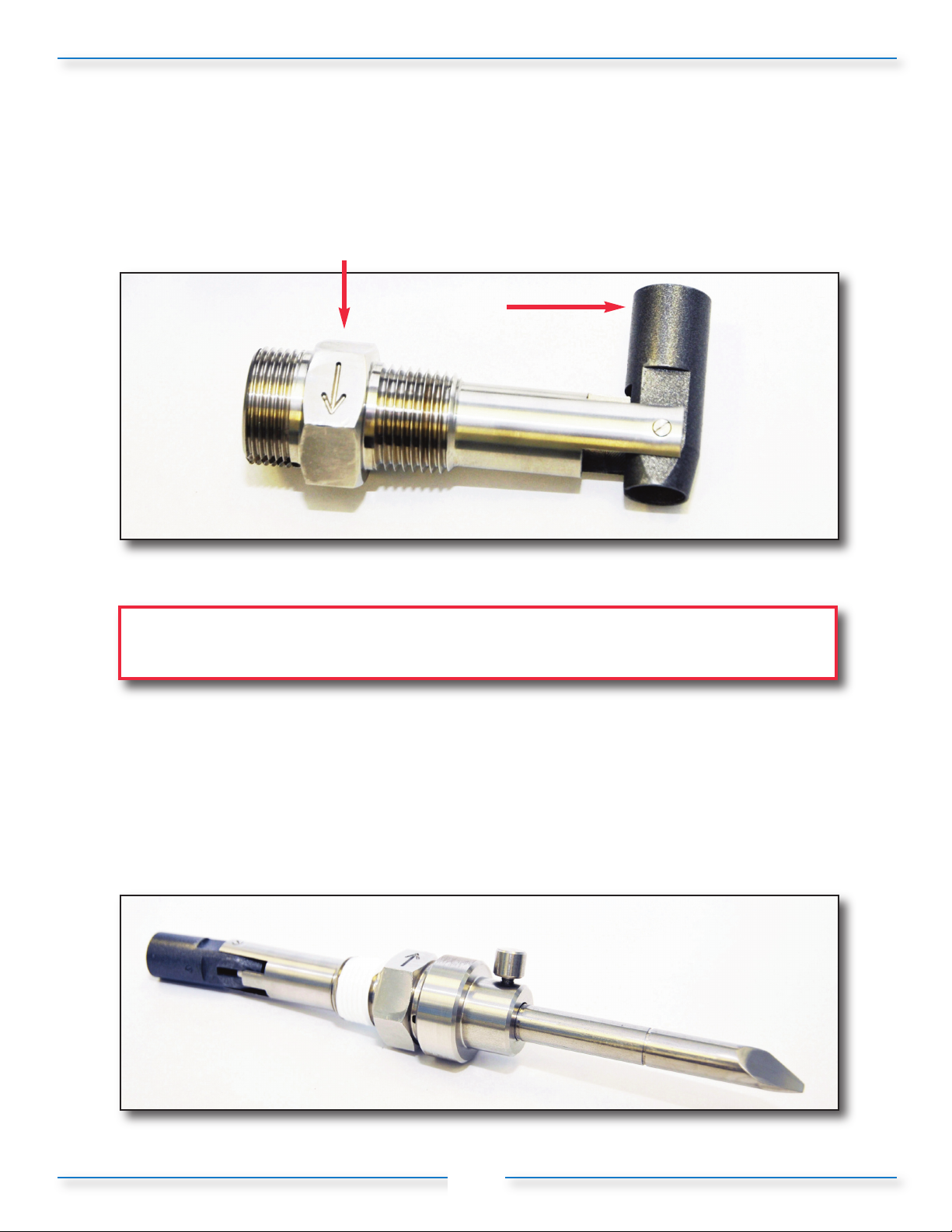
6) Screw threaded insert into the inlet tap of the control valve, tighten properly and align so that the
arrow points to downstream flow making sure that the wrench flat with arrow is level with the
valve cover,and the measurement cylinder is facing (parallel to) upstream flow. (Figure 2-6).
Figure 2-6
Please note that the flat with the engraved arrow must be positioned so that arrow
is in line with the flow direction. Failure to do so will result in inaccurate readings.
7) Measurement Cylinder Swivel Procedure
a) Position of Threaded Insert + Insertion Tool, just prior to installation into valve, (Figure 2-7).
b) Slide Insertion Tool straight out, then insert the opposite side flat tipped end into the
threaded insert.
c) Insert tool, flat tipped end first, making sure to feel for the Insertion Tool to engage the
measurement cylinder, then push straight into the insert until the tool seats, which puts
the measurement cylinder to roughly 90° to the sleeve of the threaded insert (see Figure 2-8).
d) It may help to wiggle the tool slightly while pushing firmly.
Figure 2-7
9
Page 13
Section 2: Installation of the X144 e-FlowMeter (continued)
2.4 - Step-by-Step Instructions Mechanical Installation
Measurement
Cylinder swivels
to proper
position
pressure
Figure 2-8
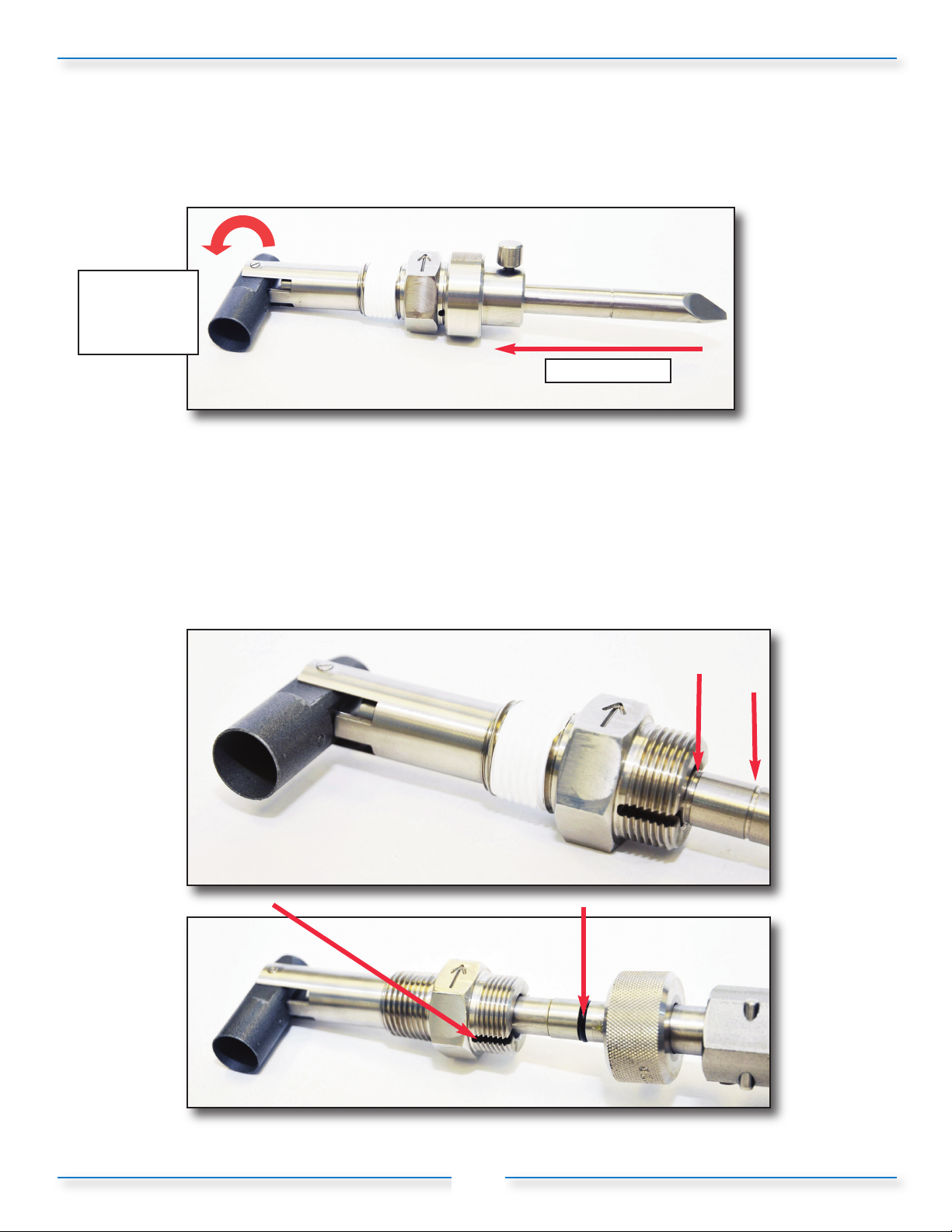
8) Once the measurement cylinder rotates, remove the tool lock then use the score marks on
the Insertion Tool to verify measurement cylinder is locked in 90° orientation, ensure that
the tool seated to appropriate ½” or ¾” score marks, (Figure 2-9).
9) Insert sensor into threaded pipe insert. Ensure that the centering pin is aligned
with the centering groove on the threaded insert, (Figure 2-10). Push firmly to
seat the o-ring.
Figure 2-9
replace this
photo with one
showing pin &
groove
Figure 2-10
10
Page 14
Section 2: Installation of the X144 e-FlowMeter (continued)
2.4 - Step-by-Step Instructions Mechanical Installation
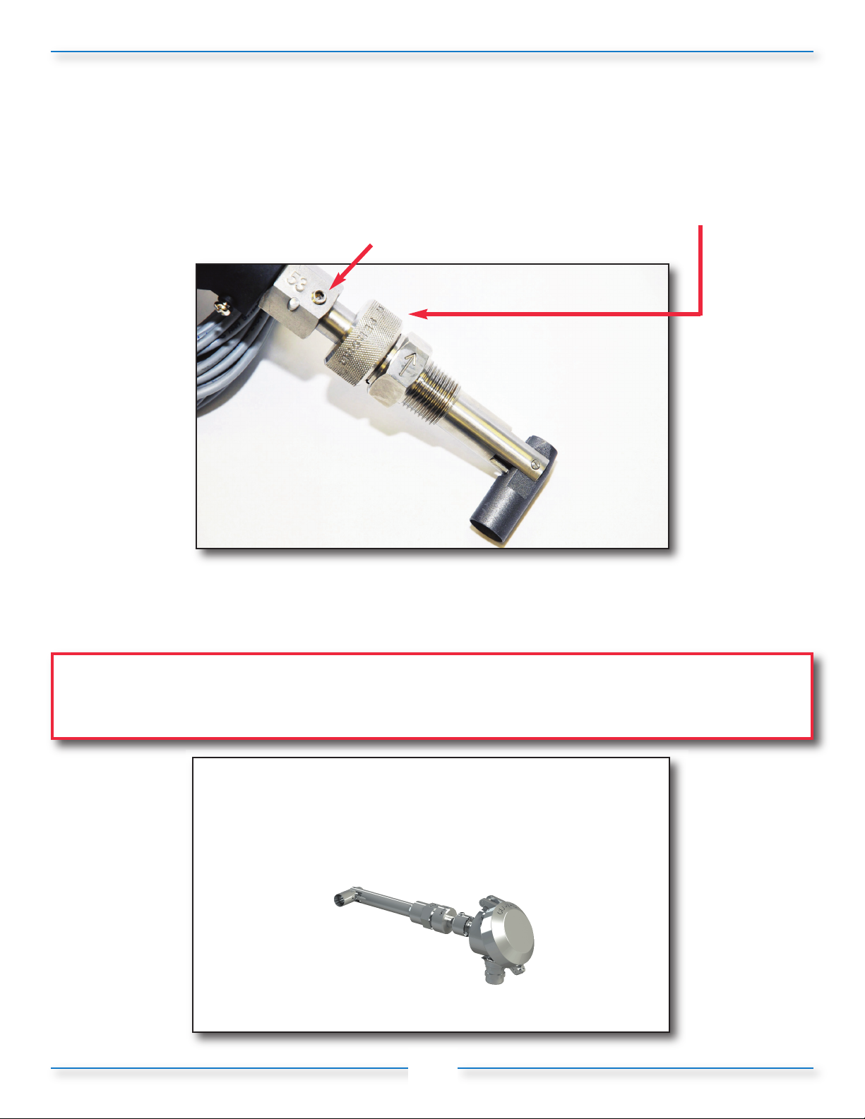
10) Ensure that the e-FlowMeter is properly seated and tight using the knurled lock, hand tight only,
(Figure 2-11). Tighten M3 Allen set screw to lock orientation of head.
Figure 2-11
CAUTION: If the e-FlowMeter is not properly seated, it will not hold pressure and will leak. To avoid
potential damage from water leaking at the tap, be sure that the e-FlowMeter is tight and
seated.
Log onto www.cla-val.com
and click on the X144 e-FlowMeter icon to
learn more
11
Page 15
Section 2: Installation of the X144 e-FlowMeter (continued)
24 VDC
white wire
4-20 mA
brown wire
Connect brown wire
to ground wire if
no accessory devices
are being used
Note: When connecting 4-20mA
circuit, place all reading/ logging
equipment (if any) in series
X144 e-FlowMeter™
Data
Logger
Digital
Multi-Meter
SCADA
System
GSM/GPRS
Telemetry
Key: optional accessory equipment not supplied with e-FlowMeter
ed
k
ll
w
hi
e
o
1
2 3 4 5 6
7
8
10 - 30 VDC
+
-
Power Supply/Battery
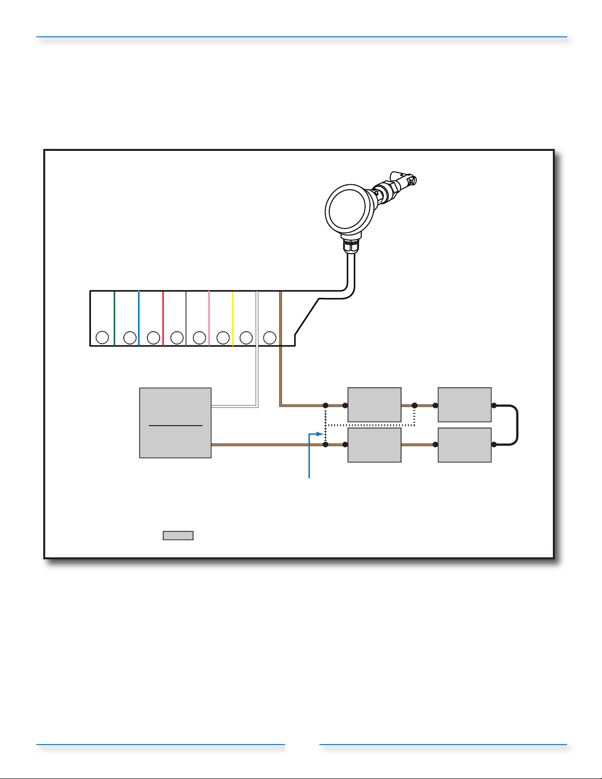
2.5 - Step-by-Step Instructions: Electrical Installation for General Applications
Figure 2-12: X144 e-FlowMeter Cable Options
r
n
t
o
e
wn
r
w
1) Connect the wire marked “4-20mA” to the proper recording/measurement device. Connect that
device per manufacturer’s recommendations. If no logging/DAQ/SCADA system is available,
attach the “4-20mA” wire to the ground of the power supply.
2) Connect the wire marked “24 VDC” to either 12 VDC or 24 VDC, as available.
3) If possible, use handheld multi-meter to verify mA readings prior to leaving installation.
a) When there is no flow present, the X144 e-FlowMeter should read very close to 4.0 mA.
4) A possible power supply for the X144 e-FlowMeter is the Cla-Val X143MP Micro Turbine Power
Generator. (See Figure 2-16, Page 14)
Note: AC/DC converters must be properly grounded in order to prevent electronic noise.
12
Page 16
Section 2: Installation of the X144 e-FlowMeter (continued)
l
P
l
(
)
r
n
e
y
k
ll
w
hi
n
y
C,
1
0
ed
y
k
hi
e
n
e
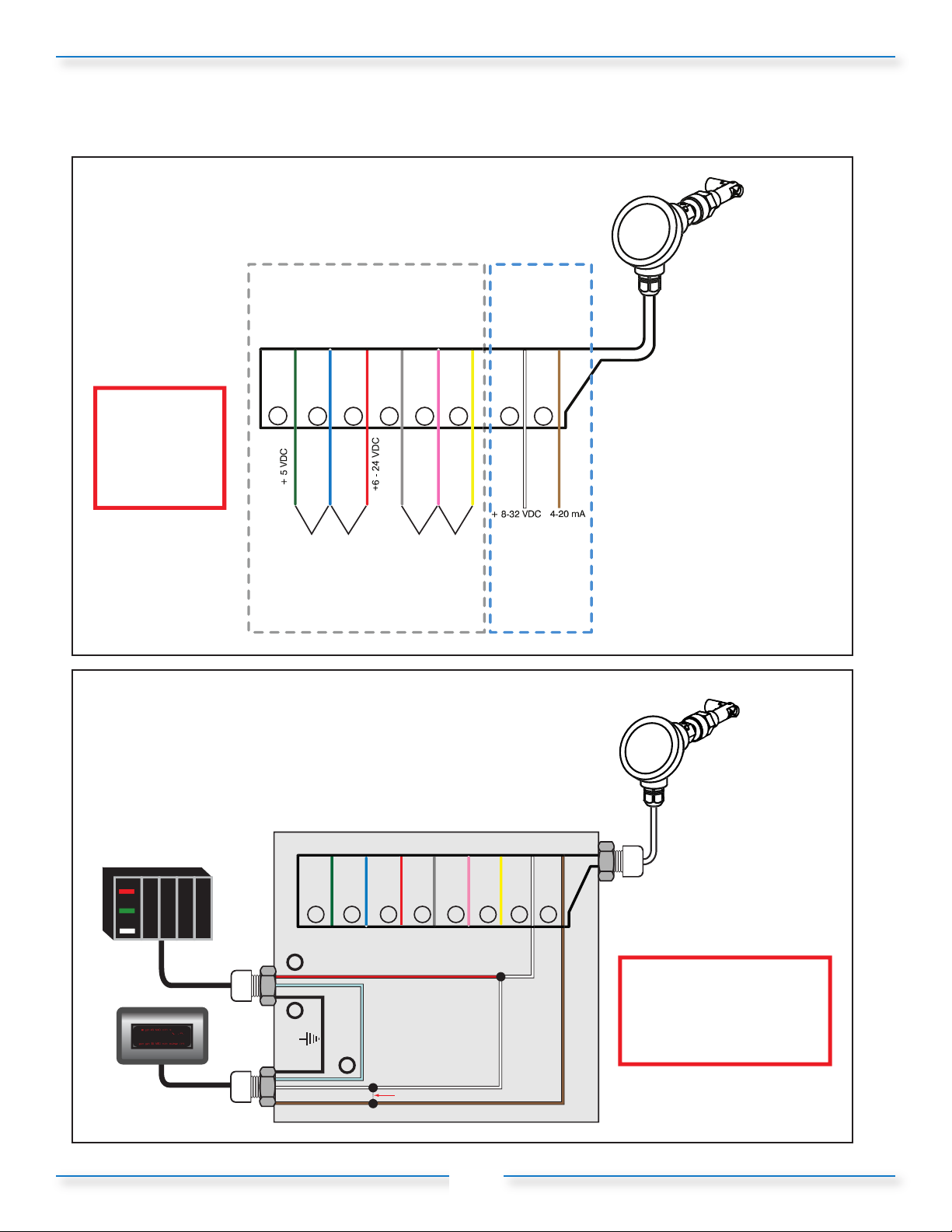
2.6 - Wiring Installation
Figure 2-13:
X144 e-FlowMeter Wiring Diagram
X144
e-Flow Mete
Pulse Output
Circuit Wiring
4-20mA Loop
Power
Circuit Wiring
CAUTION:
Do not connect
Pulse Output Circuit
and 4-20mA Loop
Power Circuit
Wiring simultaneously.
Damage will occur.
1
gree
+ 5VDC 1.0 A mi
lu
3
2
-0V (com)
- 24 VD
ower Suppl
ed
A min.
.
ower Supply
in
gre
5 6
4
se
u
ta
Figure 2-14:
X144 e-FlowMeter Wiring Diagram
for SCADA using 4-20mA Output
o
e
NPN
ransistor
Pulse
te
rown
w
7
8
X144 e-Flow Meter
ellow
whit
t
w
7 8
row
1
+
SCADA Power
lue
r
2
3
n
re
4
5 6
CAUTION:
Do not connect 4-20mA
-
001250.0
SCADA
signal return
signal out
SCADA
+
analog output
bypass if no display
Junction Box
13
brown
(white) wire simultaneously
with pulsed circuitry.
Damage will occur
Page 17
Section 2: Installation of the X144 e-FlowMeter (continued)
y
d
k
ll
w
hi
d
k
ll
w
hi
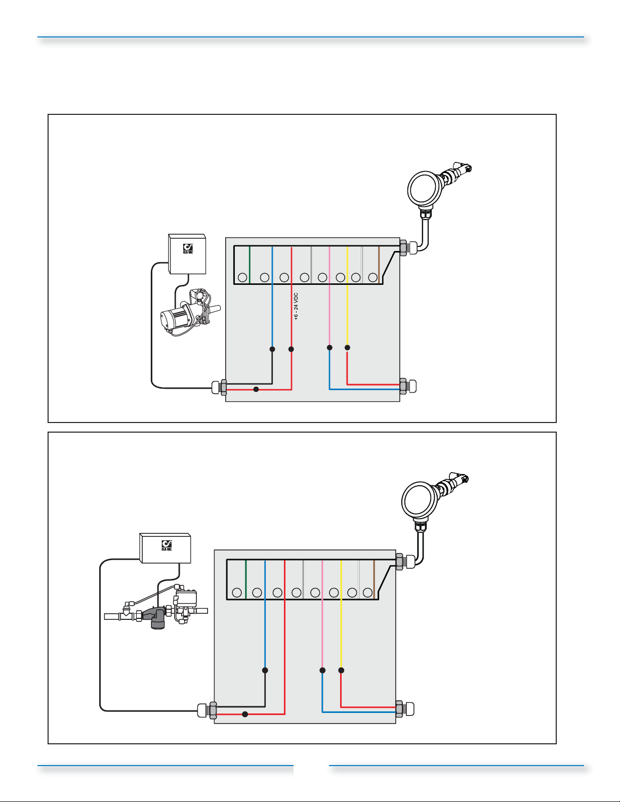
2.6 - Wiring Installation
Figure 2-15:
Wiring Diagram: X144 e-FlowMeter
with X143IP Intermediate Power Generator
X144 e-Flow Meter
X143IP
Control Box
X143IP
reen
1
re
2
3
- 0V
red
blue
X143IP
Intermediate
Power Generator
black
red
12/ 24 VDC
- 0V
- 0V
Junction Box
Figure 2-16:
Wiring Diagram: X144 e-FlowMeter
with X143MP Micro Power Generator and
X143MP
Control Box
o
e
yellow
red
te
w
7 8
rown
n
gre
4
5 6
pink
blue
X144 e-Flow Meter
X143MP
(lead battery)
X143MP Micro
Power Generator
black
red
re
2
1
3
- 0V
blue
- 0V
- 0V
n
4
5 6
pink
blue
o
e
yellow
red
te
w
7 8
rown
Junction Box
14
Page 18
SECTION 3: X144 e-FlowMeter Operation
3.1 – Starting Operation
Follow this procedure when starting the installation for the first time or after shutting the system down for
maintenance of the Control Valve.
1) Check all connections to power supply and other User Devices (data loggers, telemetry, etc.)
2) Ensure all wiring is properly connected.
3) Open shut-off valves and allow water into the system.
4) Check the system for water leaks, at both the tapered threads, as well as the straight threads
with knurled lock.
5) Check surrounding piping and auxiliary equipment for leaks.
6) Check X144 e-FlowMeter output and verify proper operation at current flow condition
(per table 1):
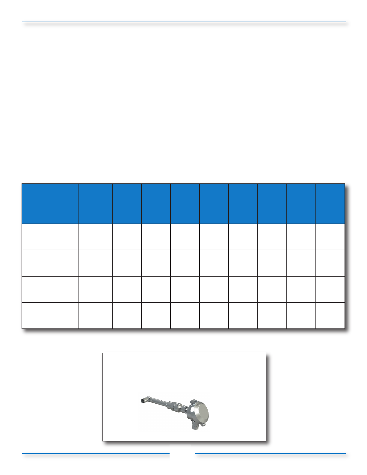
Table 1: Minimum and Maximum Flow values for X144 e-FlowMeter
Line Size
inches (mm)
Minimum Flow
(GPM)
Maximum Flow
(GPM)
Minimum Flow
(l/S)
Maximum Flow
(l/S)
*2" X144 e-FlowMeter may be installed on new valves only
Note: Consult Factory for Angle Pattern Applications
*2"
(50mm)
(100-49 Body)
10 10 15 25 60 100 160 230 360
210 300 460 800 1800 3150 4950 7000 11000
0.65 0.65 1.0 1.5 3.8 6.3 10.0 15 23
13.3 18.9 29 50 110 200 310 440 700
2-1/2"
(65mm)3"(80mm)4"(100mm)6"(150mm)8"(200mm)
Log onto www.cla-val.com
and click on the X144 e-FlowMeter
icon to learn more
10"
(250mm)
12"
(300mm)
16"
(400mm)
15
Page 19
SECTION 3: X144 e-FlowMeter Operation
3.2 – Stopping Operation/Removal of X144 e-FlowMeter
1) Close the shut-off valves to stop the flow of water, bleed pressure.
2) Disconnect all wiring.
3) Follow the steps below to remove the X144 e-FlowMeter
from the Control Valve.
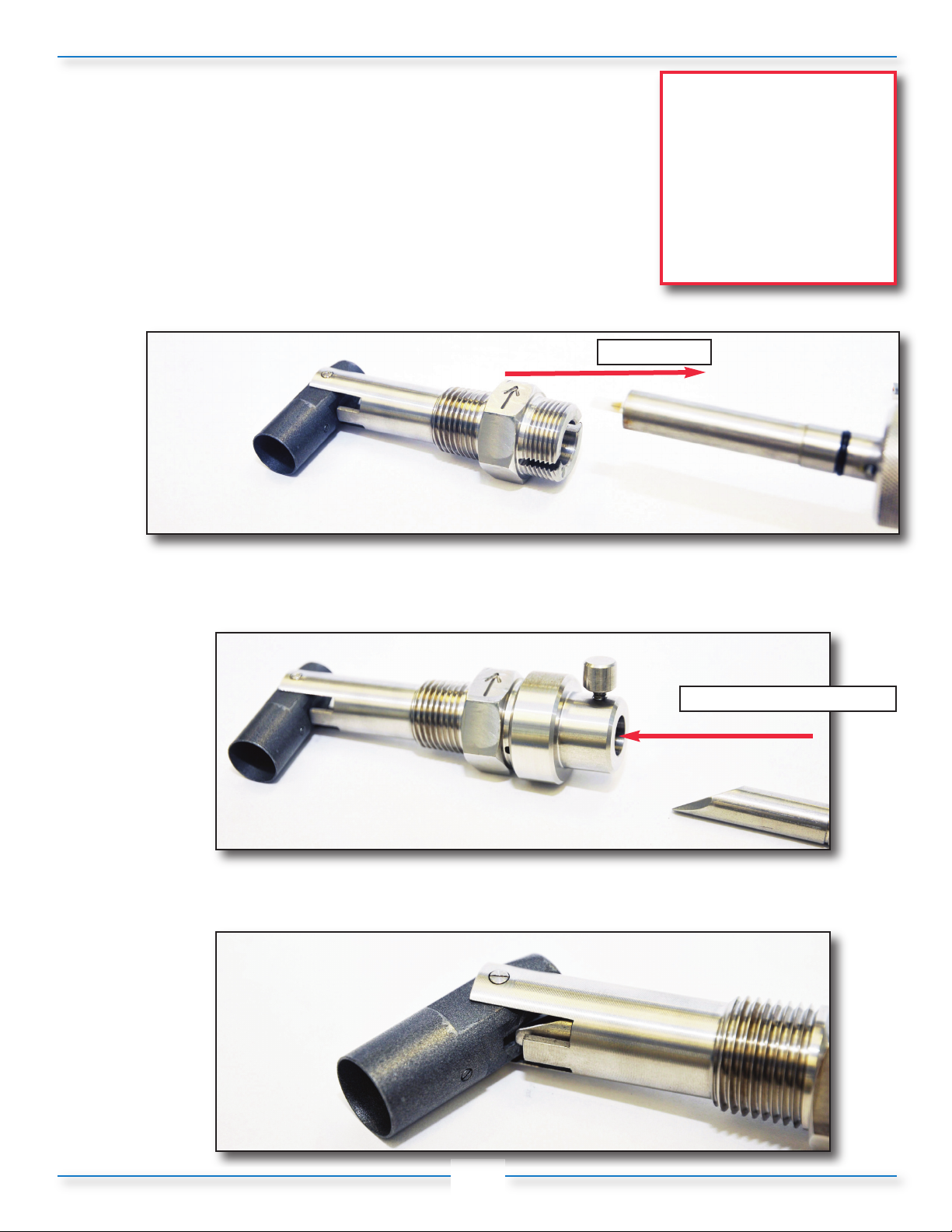
a) Unscrew knurled lock and remove the sensor from the
threaded insert and set aside, making sure to protect the sensor tip.
Figure 3-1
CAUTION 1: Failure to use
the provided Insertion Tool
WILL result in damage to
the e-FlowMeter
CAUTION 2: To avoid injury,
isolate the valve and bleed
pressure prior to removing
the e-FlowMeter
remove
b) Orient the Insertion Tool so that the bevel is facing downstream, away from the centering groove,
and insert into the threaded insert.
insert and apply light force
Figure 3-2
c) The tool will engage the top face of the measurement cylinder and force it to the 45° position,
as shown below.
Figure 3-3
16
Page 20

SECTION 3: X144 e-FlowMeter Operation
3.2 – Stopping Operation / Removal of X144 e-FlowMeter
d) Slide Insertion Tool straight out, then rotate 180 degrees so that the bevel is facing upstream of the
valve, which is now facing the same direction of the centering groove, as shown below.
upstream direction,
same side as groove
Figure 3-4
e) The lip of the Insertion Tool will engage the inside of the Measurement Cylinder, as shown below.
pull out tool and
rotate 180°
centering
groove
Figure 3-5
Insertion Tool lip
f) Once engaged, use light force to straighten the measurement cylinder, and then lock the insertion
tool in place with the Insertion Tool lock, as shown below.
Measurement Cylinder
inside of
Figure 3-6
4) Re-install the pipe plug into the open boss of the valve.
17
Page 21
SECTION 4: Maintenance and Repair
4.1 – Routine Maintenance
CAUTION: Always disconnect the power supply, isolate and depressurize the system before performing any
maintenance or repair. Failure to so may result in injury to personnel or damage to equipment.
The X144 e-FlowMeter does not have any moving mechanical parts and so is not affected by fatigue wear
from mechanical stress. The system should be inspected routinely for leaks. An inspection should consist of
the actions in steps 1-2 procedure outlined in section 3.1. It is recommended the equipment be turned off during
inspection.
4.2 – Cleaning debris from measurement cylinder
If the readings from the X144 e-FlowMeter begin to act in an unreliable manner, then
the measurement cylinder should be inspected and cleaned out to ensure proper operation.
Required Tools:
• Insertion tool
• Adjustable wrench
• Small pick or small screw driver for clearing the debris
• Tweezers or small needle-nosed pliers
Procedure
1) Close the shut-off valves to stop the flow of water.
2) Disconnect all wiring.
3) Go through the removal steps (section 3.2) to remove the X144
e-FlowMeter from the Control Valve,using the provided Insertion
Tool
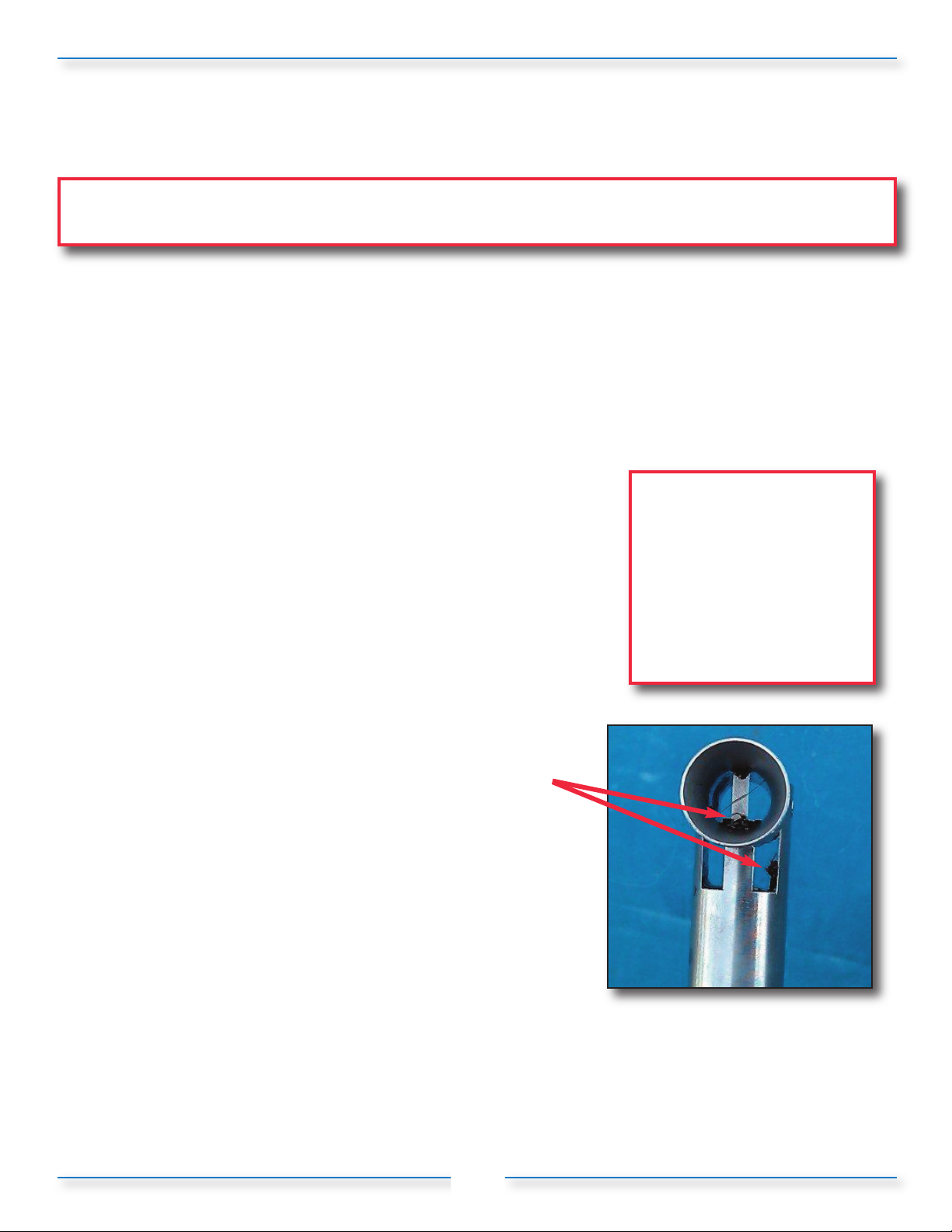
4) With the sensor still removed from the threaded insert, inspect
measurement cylinder; looking specifically for debris caught on
the bluff body, as shown in Figure 4-1.
5) Use pick or small screw driver and tweezers to remove all of
the debris from the measurement cylinder, bluff body and
anywhere else that it has accumulated.
6) Reinstall X144 according to the installation steps in section 2;
verify operation per operation instructions in section 3.
4.3 – Dealing with Sensor Tip Damage
1) If the Sensor Tip is bent, broken or damaged in the course of
handling or installation, the X144 e-FlowMeter will not function
properly. The sensor should be straight with respect to the
sleeve. Since it is designed to sense micro-motion, if the sensor
is forced to enough to detect the movement with the naked eye, it
may have been damaged. In that case, contact Cla-Val
Customer Service.
CAUTION 1: Failure to use
the provided Insertion Tool
WILL result in damage to
the e-FlowMeter
CAUTION 2: To avoid
injury, isolate the valve and
bleed pressure prior to
removing the e-FlowMeter
Figure 4-1
18
Page 22
SECTION 5: Specifications
Table 2: Electrical Specifications
Enclosure Stainless Steel (standard)
Output Signal Options:
• Digital Pulse, proportional
to flow rate
• Transistor (NPN) Pulse,
proportional to flow rate
Display Option
• Analog output: 4 mA to 20 mA analog current loop
• Current proportional to flow rate
• Power supply: 12 VDC to 30 VDC compliance
• 4 mA - zero flow; 20 mA maximum flow as listed in Table 6 below
• Other 20 mA settings can be configured by the factory or
reconfigured in the field by authorized personnel
• LCD display alternately shows one lines of seven-digit data;
i.e. flow rate + totalizer
Table 3: Mechanical Specifications
Type Fixed Insert
• Drinking Water
Measurable Fluids
Valve Sizes Full Port: 2.5, 3, 4, 6, 8, 10, 12, 16-inches; Reduced Port: 4”- 24-inches
Fluid Temperature 15° F - 175° F (-10° C - 80° C)
Fluid Pressure
• Irrigation Water
• Reclaimed Water
The pressure rating for the X144 e-FlowMeter equals but
is not greater than the pressure rating of the valve in which
it is installed
Classification
Ambient Temperature -20° F to 140° F (-29° C - 60° C)
Flow Range
Measuring Units
Accuracy (combined linearity
and repeatability)
Wetted Parts
Straight Pipe Run See Recommended Installation Chart, Figure 2-1
Clearance from
wall or other
obstruction
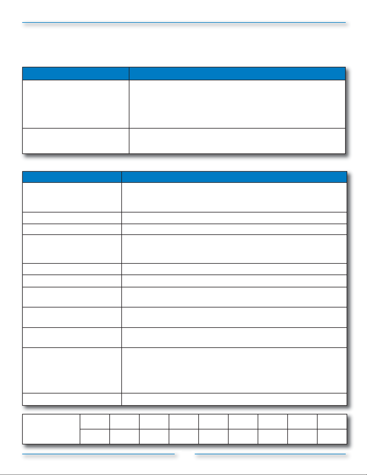
2” 2-1/2” 3” 4” 6” 8” 10” 12” 16”
10.0” 10.0” 10.0” 10.5” 10.5” 14.25” 14.25” 19.0” 19.0”
IP 68 Submersible
• Minimum: 1.0 foot per second (FPS) (0.3 m per second)
• Maximum: 20.0 foot per second (FPS) (6.1 m per second)
• English US Gallons Per Minute (GPM)
• Metric: Liters per second
• +/-2 % of full scale
• Vortex Sensor: (plastic)
• Measurement Cylinder and Bluff Body: Teflon® Coated Stainless Steel
• Stem: Stainless Steel
• O-Rings: BUNA N
• Compression Fitting: 304 Stainless Steel
19
Page 23
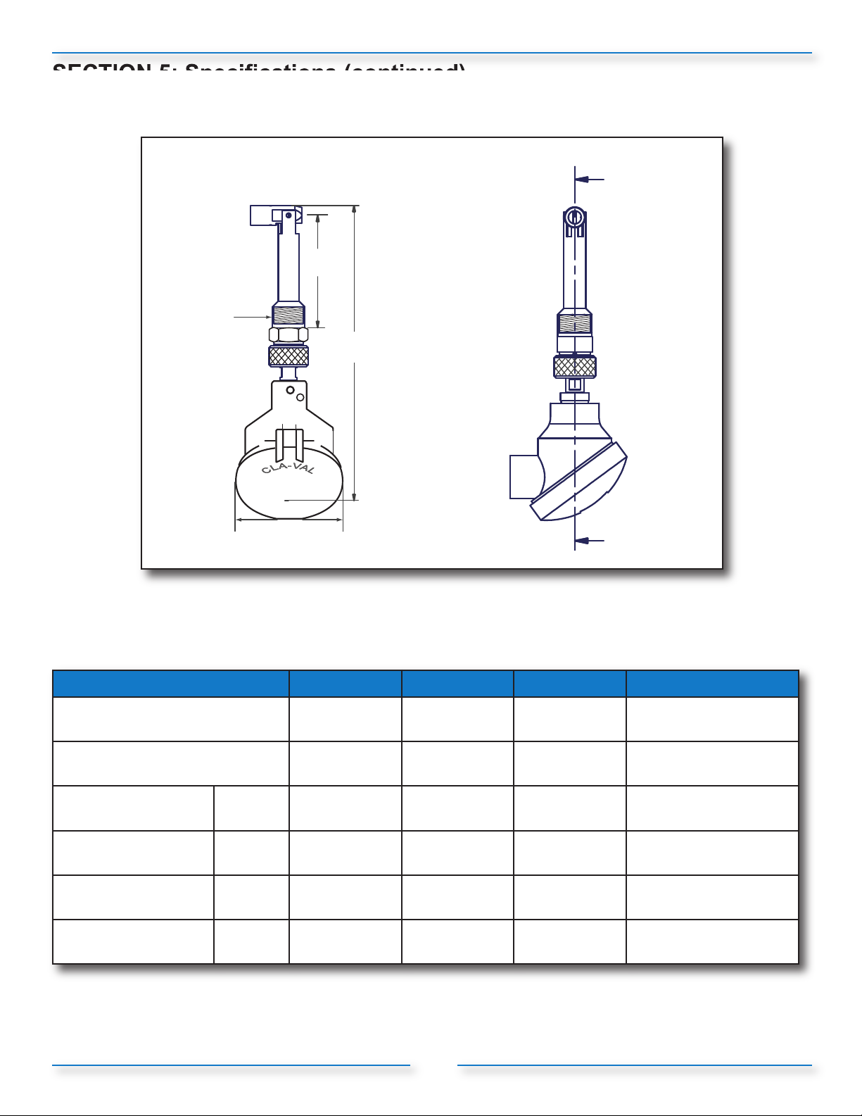
SECTION 5: Specifications (continued)
A
Dimensional Data
B
C
D
Figure 5-1: X144 e-FlowMeter
Table 4: X144 e-FlowMeter Dimensions
X144 Sizes
Full Port Valve Sizes 2*, 2-1/2, 3 4, 6 8, 10
Reduced Port Valve Sizes 4 6, 8 10, 12
Overall Length
(in inches)
Insertion Length
(in inches)
Pipe Thread
(NPT)
Overall With
(in inches)
A 7.9 8.7 12.4 23.2
B 2.3 2.8 6.8 17.6
C
D 3.25 3.25 3.25 3.25
1 2 3 4
1/2" 3/4" 1" 1"
12, 14, 16*
14, 16, 18, 20, 24*
*2" X144 e-FlowMeter may be installed on new valves only
Note: Consult Factory for Angle Pattern Applications
20
Page 24
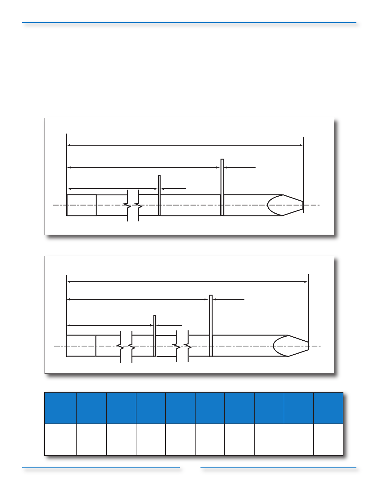
SECTION 5: Specifications (continued)
A
Insertion Tools: Overall Length
•T1 = 6-1/2”
• T2 = 14-1/2”
Figure 5-2: X144 Insertion Tool - T
6.5-inches
4.76” 0.04”
3.43” 0.04”
Figure 5-3: X144 Insertion Tool - T
14.5-inches
1
2
12.45” 0.04”
7.63” 0.04”
Table 5: X144 Insertion Tools
X144
Size
Tool T
2" 2-1/2" 3" 4" 6" 8" 10" 12" 16"
1
T
1
T
1
A
T
1
21
T
1
T
2
T
2
T
2
T
2
Page 25
SECTION 5: Specifications (continued)
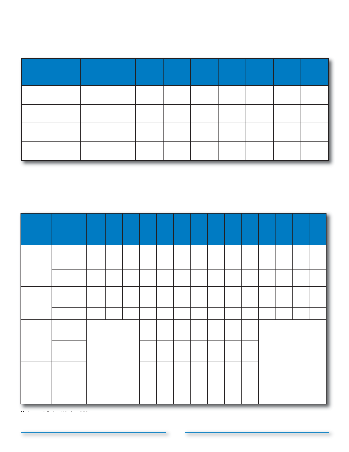
Table 6: X144 e-FlowMeter Operational Flow Ranges
Line Size
inches (mm)
Minimum Flow
(GPM)
Maximum Flow
(GPM)
Minimum Flow
(l/S)
Maximum Flow
(l/S)
(50mm)
(100-49
Body)
10 10 15 25 60 100 160 230 360
210 300 460 800 1800 3150 4950 7000 11000
0.65 0.65 1.0 1.5 3.8 6.3 10.0 15 23
13.3 18.9 29 50 110 200 310 440 700
If required, the factory settings of the e-FlowMeter can be adjusted. A Cla-Val USB Adapter Cable is required and can be
Go to http://www.cla-val.com/software-driver-library.php for software/instructions.
2-1/2"
(65mm)3"(80mm)4"(100mm)6"(150mm)8"(200mm)
ordered by contacting the factory at 800.942.6326.
10"
(250mm)
12"
(300mm)
16"
(400mm)
Table 7: X144 e-FlowMeter Analog Range (4-20mA Scaling): Factory Settings
**2"
*2"
Port Style
Line Size
inches (mm)
(100-49
Body)
(50)
2-1/2"
(65)3"(80)4"(100)6"(150)8"(200)
10"
(250)
12"
(300)
14"
(350)
16"
(400)
18"
(450)
20"
(500)
24"
(600)
30"
(750)
Full Port
Valves
4mA = 0
(GPM -
l/s)
Full Port
Pulse
Weight*
Reduced
Port
Valves
4mA = 0
(GPM-
l/s)
Reduced
Port
Valves
Pulse
Weight*
20mA Range
(GPM)
20mA Range
(l/s)
Gal/Pulse 5 6.5 9.5 17 38 65 100 150 175 235 290 365 515 865
l/Pulse 19 25 36 65 145 245 380 565 660 890 1100 1380 1950 3275
20mA Range
(GPM)
20mA Range
(l/s)
Gal/Pulse 11.5 26 48 75 95 130 155
l/Pulse 44 99 180 285 360 495 585
260 375 575 1000 2250 3900 6000 8750 10500 14000 17500 22000 31000 52000
16.4 23.7 36.3 63.1 140 245 380 550 660 880 1100 1390 1950 3280
not available
Notes: * Pulse Width = 250ms.
**2" X144 e-FlowMeter may be installed on new valves only. Consult Factory for Angle Pattern Applications
675 1600 2900 4500 5650 7750 9350
42.5 100 180 285 355 490 590
Consult Factory
22
Page 26
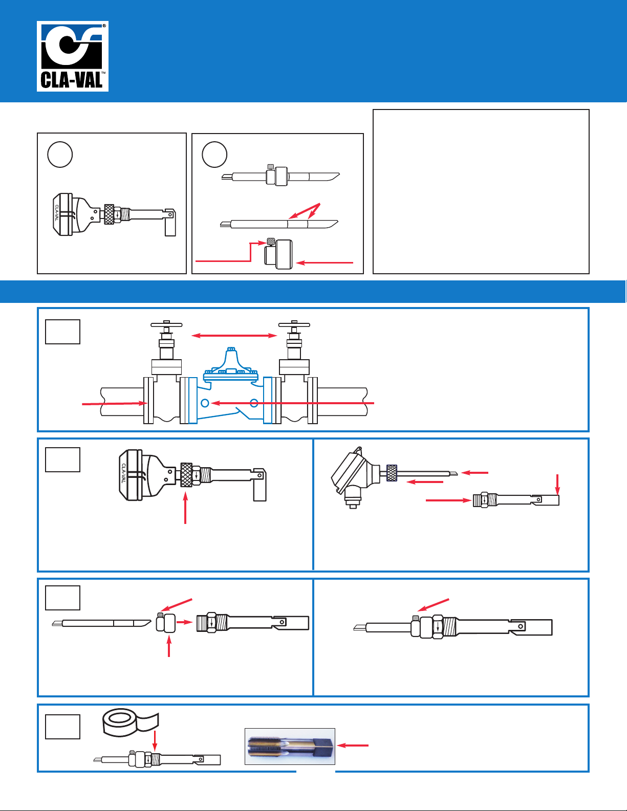
X144 e-FlowMeter
Quick Start Installation & Removal Instructions
X144 e-FlowMeter Included Hardware
1
patent pending
Complete
e-FlowMeter
Assembly
a) Insertion Tool
b)
Thumb Set
Complete Installation Kit
2
Screw
Step-By-Step X144 e-FlowMeter Installation Instructions
1
flow
Isolation Valves
CLA-VAL
Score Marks
Locking
Collar
Parts List
1) X144 e-FlowMeter Assembly with
30 foot cable
2) Installation Kit containing:
a) Insertion Tool
b) Locking Collar with Thumb Set Screw
(a and b come assembled)
Installation Kit Part Numbers:
Small (2.5” - 6” + 8” reduced Port): 208450-21K
Large (8” Full Port - 16”): 208450-20A
Step 1: Take necessary safety precautions
• Isolate the control valve using main line
isolation valves
• Bleed pressure from valve before removing
body plug
• Remove an inlet body plug
NOTE: If both inlet body tappings are used for
the pilot system, consult factory for correct
modification instructions.
2
Step 2A:
Loosen Knurled Lock Nut on e-FlowMeter Assembly
3
Step 3A: Screw Locking Collar on straight threads. Insert
angled end of provided tool as shown, until it stops
Thumb Set Screw
Locking Collar
tape not supplied
4
Sensor/Head Assembly
sensor
tip
Threaded Swivel Insert
Step 2B: Pull apart. Straighten Measurement Cylinder by
hand. Set aside Sensor/Head in safe location,
protecting sensor tip
Thumb Set Screw
Step 3B: Tighten Thumb Set Screw
Step 4: Apply Teflon® tape to NPT Threads
• Check threads on valve
• Use thread chasing tool (not supplied), if
necessary
Measurement
Cylinder
23
Page 27
X144 e-FlowMeter
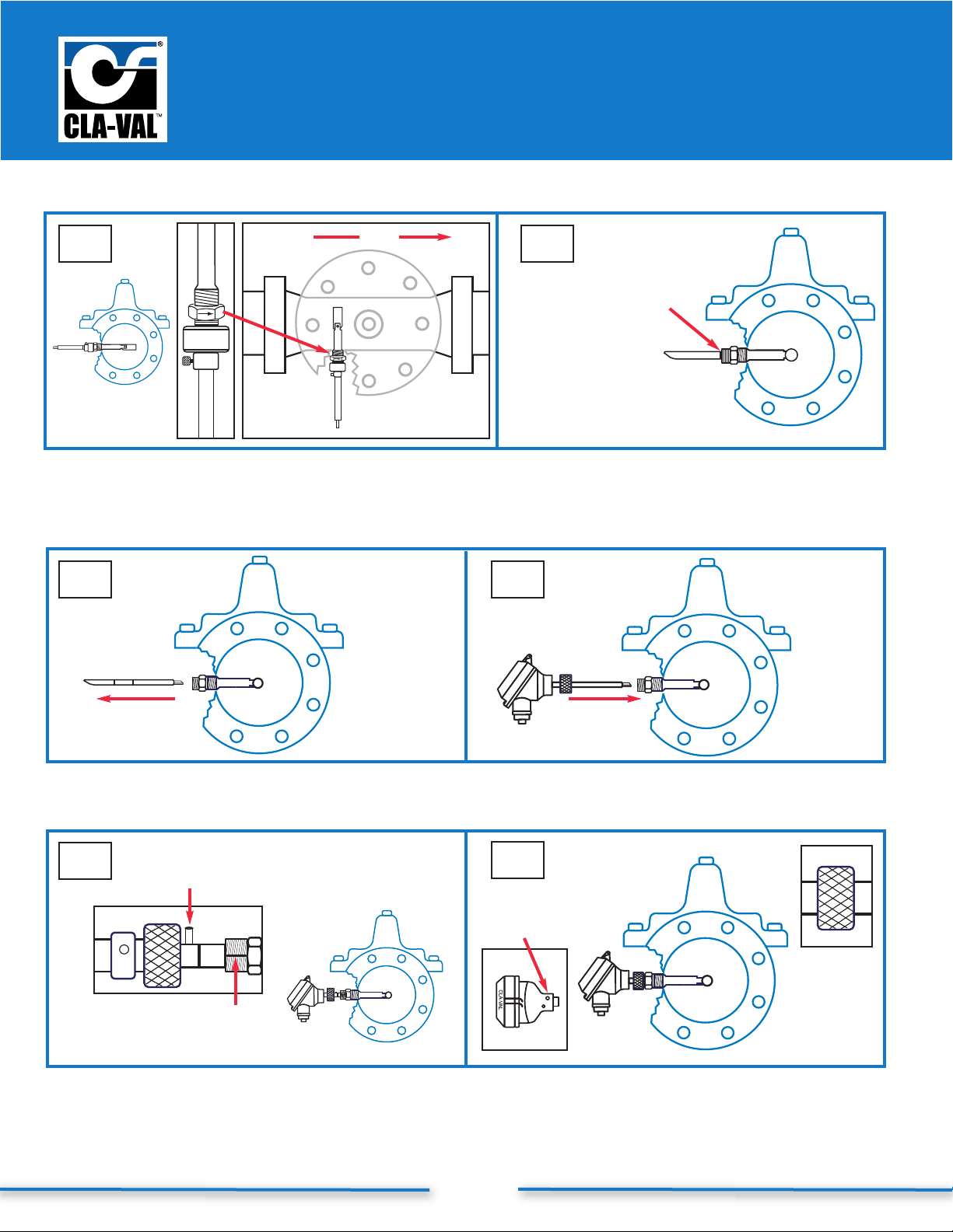
Quick Start Installation & Removal Instructions
Step-By-Step X144 e-FlowMeter Installation Instructions (continued)
flow
inside view
top view
Step 5: Insert straightened Swivel Insert/Measurement
Cylinder Assembly into valve, orient arrow on
wrench flat to point downstream
7
65
Verify score mark is
flush with flat face
of straight thread
to ensure full
engagement
Step 6: Loosen Thumb Set Screw. Remove Locking Collar
from tool. Remove tool and re-insert opposite end into
Swivel Assembly. Engage the tool and push firmly to orient
Measurement Cylinder 90˚ into flow path
8
Step 7: Remove tool from Threaded Swivel Insert
9
Step 9: Line-Up Centering Groove on straight threads
with Centering Pin; push to seat o-ring
Centering
Pin
Centering
Groove
Step 8: Insert tip of e-FlowMeter Sensor/Head Assembly
into Threaded Swivel Insert
10
Allen Set
Screw
Knurled
Lock
Step 10: HAND TIGHTEN Knurled Lock onto straight
threads. Tighten Allen Set Screw with M3 Allen
Wrench to lock Sensor Head Assembly.
Proceed in accordance with Wiring Diagram
24
Page 28
X144 e-FlowMeter
l
P
l
(
)
r
n
e
y
k
ll
w
hi
n
y
C,
1
0
Quick Start Installation & Removal Instructions
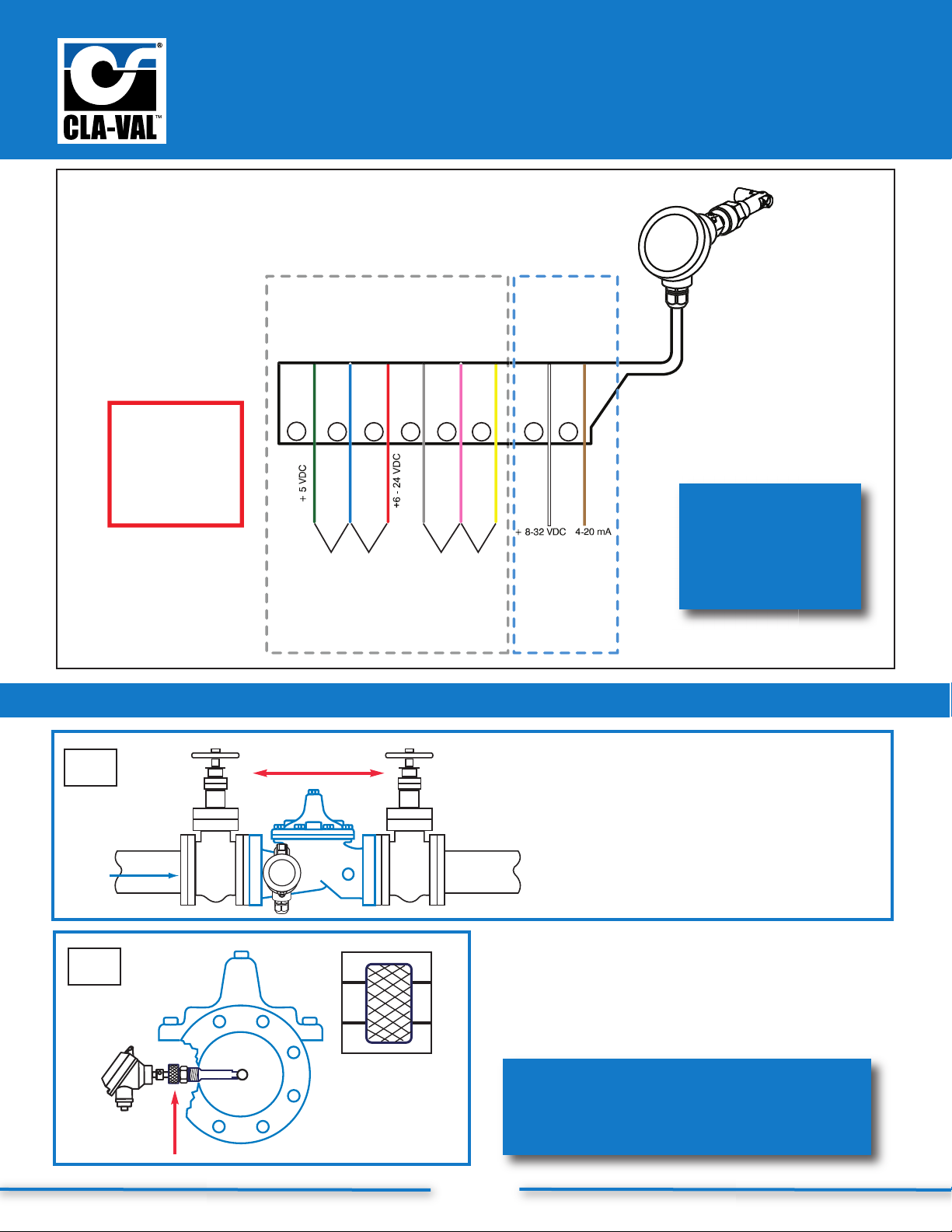
Standard Wiring
X144
e-Flow Mete
Pulse Output
Circuit Wiring
4-20mA Loop
Power
Circuit Wiring
CAUTION:
Do not connect
Pulse Output Circuit
and 4-20mA Loop
Power Circuit
Wiring simultaneously.
Damage will occur.
1
flow
ed
lu
gree
1
2
-0V (com)
3
gre
4
in
5 6
o
e
te
rown
w
7
8
for additional
wiring diagrams,
download N-144
IOM Manual at
www.cla-val.com
ower Suppl
+ 5VDC 1.0 A mi
A min.
.
ower Supply
- 24 VD
se
u
ta
NPN
ransistor
Pulse
Step-By-Step X144 e-FlowMeter Removal Instructions
Isolation Valves
CLA-VAL
Step 1: Take necessary safety precautions
a) Isolate the control valve
using main line isolation valves
b) Bleed pressure from valve before
removing the e-FlowMeter
c) Disconnect power to all electronic
devices on valve, including e-FlowMeter
2
Step 2: After isolating the valve, bleeding pressure and
disconnecting electronic devices, hand loosen the
Knurled Lock from straight threads
Knurled
Lock
25
call 800.942.6326 for assistance
or log-on to
www.cla-val.com for more information
Page 29
X144 e-FlowMeter
Quick Start Installation & Removal Instructions
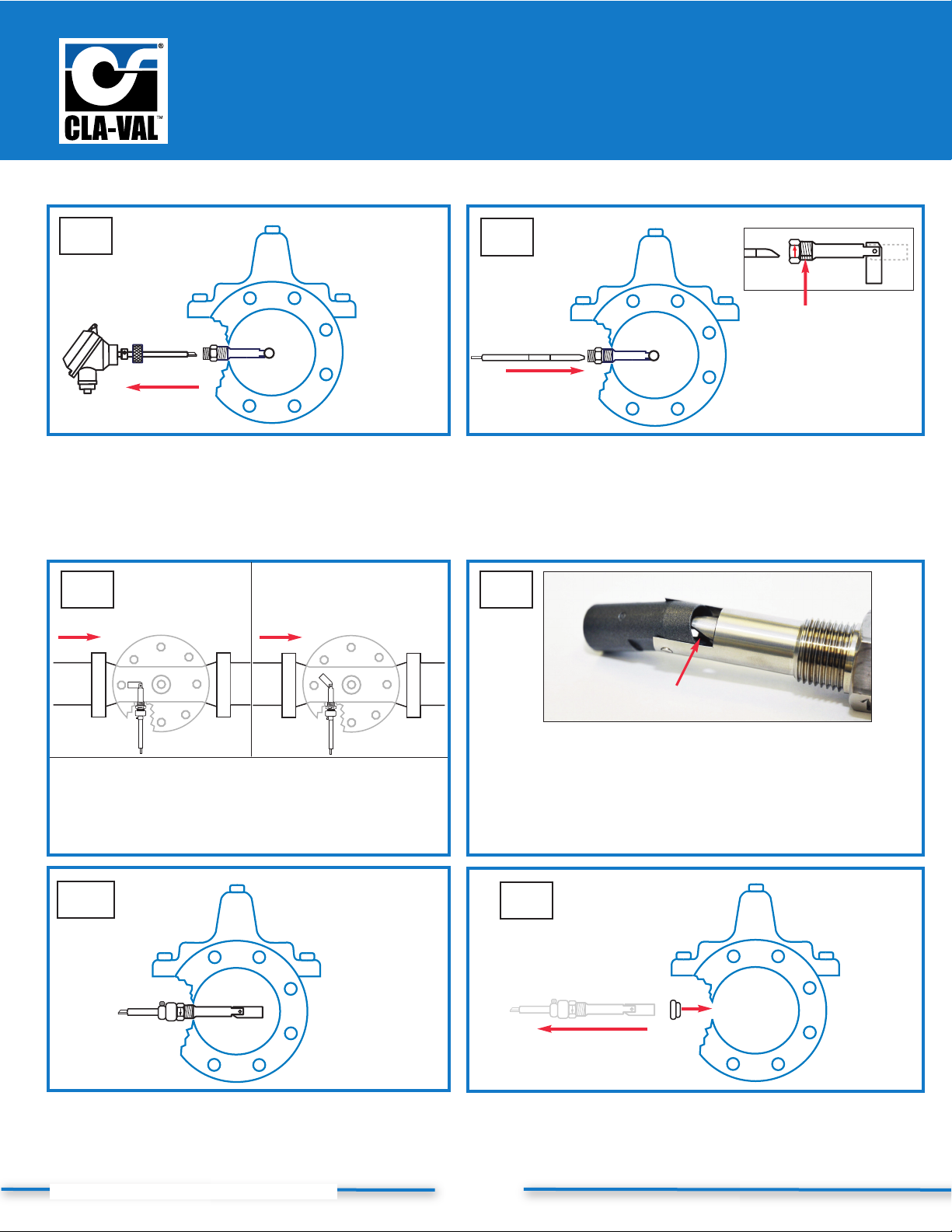
Step-By-Step X144 e-FlowMeter Removal Instructions (continued)
3
Step 3:
• Remove the e-FlowMeter Sensor/Head Assembly by
pulling straight outward, being careful not to hit the
sensor tip on the Threaded Swivel Insert tube
• Set Sensor/Head Assembly aside, taking care to
protect the sensor tip
After
flow
5
Before
flow
4
centering groove
Step 4:
• Orient the Installation Tool so that the bevel is
facing downstream, away from the centering
groove as shown in detail drawing, and insert into
the Threaded Swivel Insert
6
top view
Step 5:
• Once inserted into the Threaded Swivel Insert tube,
the Installation Tool will engage the top face of the
Measurement Cylinder and force it to the 45° position,
as shown above
top view
7
Step 7:
• Once engaged, use light force to straighten the
measurement cylinder, and then secure the Installation
Tool in place with Locking Collar in locked position
N-X144 Quick Start, Removal & Wiring (R-10-2011)
Installation Tool lip
Step 6:
• Slide Installation Tool straight out, then rotate 180° so that
the bevel is facing upstream of the valve, which is now
facing the same direction of the centering groove, see above
• The lip of the Installation Tool will engage the inside of the
Measurement Cylinder as shown in photo
8
Step 8:
• Remove Threaded Swivel Insert from the valve tapping with
the Measurement Cylinder straightened
• Insert body plug into tapping while servicing the e-FlowMeter
26
Page 30

CLA-VAL EUROPE
Chemin des Mésanges 1
CH-1032 Romanel/
Lausanne, Switzerland
Phone: 41-21-643-15-55
Fax: 41-21-643-15-50
E-mail: [email protected]
CLA-VAL UK
Dainton House, Goods Station Road
Tunbridge Wells
Kent TN1 2 DH England
Phone: 44-1892-514-400
Fax: 44-1892-543-423
E-mail: [email protected]
CLA-VAL FRANCE
Porte du Grand Lyon 1
ZAC du Champ du Périer
France - 01700 Neyron
Phone: 33-4-72-25-92-93
Fax: 33-4-72-25-04-17
E-mail: [email protected]
GLOBAL HEADQUARTERS
P.O. Box 1325
Newport Beach, CA 92659-0325
Phone: (949) 722-4800
(800) 942-6326
Fax: (949) 548-5441
E-mail: [email protected]
EASTERN REGION
6911 Richmond Highway, Suite 444
Alexandria, VA 22306
Phone: (800) 451-3030
Fax: (703) 721-1927
E-mail: [email protected]
NORTHERN REGION
280 Willard Avenue
Elgin, IL 60120
Phone: (800) 238-7070
Fax: (847) 697-5549
E-mail: [email protected]
SOUTHERN REGION
8707 Forney Road
Dallas, TX 75227
Phone: (214) 388-3493
Fax: (214) 381-9579
E-mail: [email protected]
WESTERN REGION
11626 Sterling Avenue, Suite F
Riverside, CA 92503
Phone: (800) 247-9090
Fax: (951) 687-9954
E-mail: [email protected]
CLA-VAL PACIFIC
CLA-VAL CANADA
4687 Christie Drive
Beamsville, Ontario, Canada L0R 1B4
Phone: (905) 563-4693
Fax: (905) 563-4040
E-mail: [email protected]
email:[email protected]
45 Kennaway Road
Woolston, Christchurch
8023 New Zealand
Phone: 64-39644860
Fax: 64-39644786
N-X144 IOM (R-03/2013)
www.cla-val.com • 800-942-6326
 Loading...