

Page 1

INSTALLATION / OPERATION / MAINTENANCE
Valve Position Transmitter
DESCRIPTION
The Cla-Val Model X117D Valve Position Transmitter is designed to
provide analog signal (4 - 20 mA, 2 wire) output of valve position
for Cla-Val Main Valves. A stem extension is fitted to the main
valve stem with the position transmitter mechanically linked to it.
The valve stem is mechanically linked to the electronics for an output signal that is in direct proportion to valve position. Provisions
are made for bleeding air from valve cover through a small bleed
screw and washer located on adapter.
INSTALLATION
Normally, the X117D is supplied mounted on the Cla-Val main
valve. If X117D has not been installed at factory, then install stem,
adapter, mounting bracket with transmitter (in that order) as shown
on drawing No. 200000.
OPERATION
The signal from the position sensing linkage mechanism is converted
to a two-wire 4 to 20 mA current output appearing at the output terminals. The excitation voltage ranges from 12 to 35 Volts DC.
The minimum supply voltage is a function of total loop resistance.
It may be calculated using the formula:
V(min) = (0.02 x Load Resistance) + 12 VDC
WIRING
Loosen jam nut holding transmitter and bracket to adapter when
connecting transmitter to field wiring. Tighten jam nut after connections
and adjustments are made.
Use good field wiring practices for low voltage DC analog instrumentation wiring (suggest minimum of 18-gauge multistrand wire).
Avoid potential ground loops. Calibration of transmitter should be
done with a temporary hookup of test equipment before final wiring
connections are made.
Units with NEMA 6, IP-68 enclosures have permanently attached
8' shielded cable leads. Use Red wire for positive and Black wire
for negative.
Units before Feb. 2000 have NEMA 6 enclosure with MS3102E14S-6PAmphenol plug and socket for attaching leads. Use "A"
contact for positive and "B" contact for negative.
For best noise immunity, use twisted pair shielded cable to connect
field wiring to the transmitter. The shield of the cable should be
open at the transducer and grounded at the other end. Units with
permanently attached cable are supplied with shield open inside
transmitter.
CALIBRATION
1. When properly adjusted, the transmitter will have the valve
closed position within 0% to 30% of total transmitter range and the
valve open position within 80% to 100% of total transmitter range.
At valve closed position the transmitter will have a 4 mA output and
at fully open position the transmitter will have a 20 mA output.
IMPORTANT CAUTION
spring loaded to retract and can be damaged by a sudden release
: The transmitter wire rope mechanism is
MODEL
X117D
of the wire rope. Use care to insure that it is returned to the transmitter very slowly during start up and operation. This damage may
not be covered by warranty.
2. You will need the following tools to calibrate and align the X117D:
A.) A small flat blade screwdriver (.105 Max. width x .023”
max. thickness) with non-metallic handle to fit the span and
null potentiometer
B.) A 4-20 mA calibration/tester or multiamp-tester/meter or
some means of measuring the 4-20 mA transmitter output
C.) Hand tools to adjust and tighten X117D assembly during
calibration
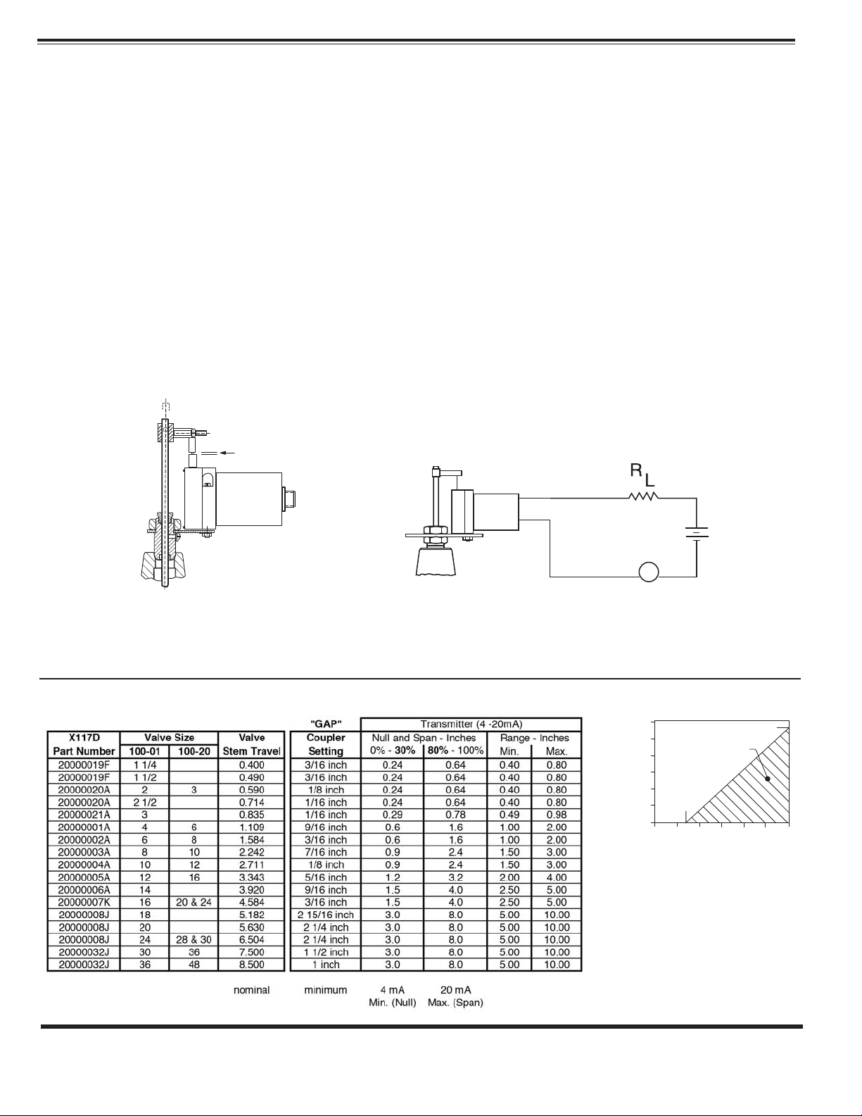
3. Preliminary mechanical settings. (Refer to Drawing No. 200000)
Be sure that the valve is in the fully closed position. See Technical
Manual for the main valve for information on this. Check that line
isolation or block valves are closed.
Adjust Nut Coupler (9) up or down on stem until gap between wire
rope end and transmitter housing is according to table (below).
The Hex Coupler (10) is used to tighten nut coupler to stem. A
minimum gap is required, see Reference Table. (Refer to Drawing
No. 200000)
Long threaded end of Hex Coupler (10) has two hex nuts (11) for
adjusting position of end of wire rope directly over the opening in
the top of the transmitter. Use one hex nut on each side of the wire
rope end. Wire rope should go vertically up and down without
noticeable angle from vertical.
4. Temporarily connect calibration equipment (milliamp meter and
power supply or portable instrumentation tester) to transmitter
wiring. Calculate total loop resistance to determine minimum load
resistor. See OPERATION
screws found on housing end.
section. Remove two calibration cover
Page 2
Refer to calibration equipment and adjust transmitter potentiometer
M
+
Meter
12 to
35 VDC
–
+
Red
Black
_
marked “NULL” until the meter reads 4 mA. A clockwise turn
increases output. Use care in adjusting the potentiometer while
turning the screwdriver.
Refer to calibration equipment (see Step 4) and adjust potentiometer
marked “SPAN” until the meter reads 20 mA. A clockwise turn
increases output. Use care in adjusting the potentiometer while
turning the screwdriver.
5. For the most accurate calibration it is necessary to open valve
fully. CAUTION: This will either allow a high flow rate through the
valve, or the downstream pressure will quickly increase to the
inlet pressure. In some cases, this can be very harmful. Where
this is the case, and there are no block valves in the system to
protect the downstream piping, it should be realized that steps
should be taken to remedy this situation before proceeding further.
Normally, block valves are to be used to protect downstream piping
while the valve is in the open position. Close downstream block
valve. Vent cover chamber to atmosphere. Slightly open inlet
block valve. Allow valve to open while fluid is vented from cover
chamber. When flow stops valve is in the fully open position.
Note: continuous leakage from cover chamber could mean additional
troubleshooting of the main valve or pilot system must be done.
6. With valve in fully open position, inspect position of wire rope
and nut coupler. (See Step 3). Adjust if necessary.
GAP
7. There is some interplay between:
1.) the “span” and “null” settings,
2.) the 4 to 20 mA signal and,
3.) the actual valve open and closed positions.
Repeat steps 4-6 above. Cycle valve from open to closed positions and check settings as necessary to achieve desired valve
position signal accuracy.
8. Remove all calibration equipment and attach permanent
wiring. Recheck wiring and output signals at remote location.
See Wiring section. Reinstall two cover screws on housing.
Recheck and tighten all fasteners. Bleed air from main valve
cover through small bleed screw and washer located on one
wrench flat of adapter.
MAINTENANCE
The X117D is constructed of durable materials which normally
requiring no lubrication or periodic maintenance. The two ‘O’ rings
(2) (p/n 00951E) in the adapter (5) that seal against the stainless
steel actuating stem (1) will need replacement if signs of leakage
at the stem occur.
Coupler gap is set with valve in fully closed position. This establishes the minimum mechanical position for 4 mA output.
ADJUSTMENT: Zero and span adjustments allow setting the 4 mA position (valve closed) within 0% to 30% of total transmitter range
and setting the 20 mA position (valve fully open) within 80% to 100% of total transmitter range.
X117D Adjustment Parameters
MAX. LOAD, R (OHMS)
Operating Zone
1200
1000
800
600
400
200
0
0
OPERATING ZONE
12V
10
15
SUPPLY VOLTAGE, V
1150 OHMS
25
30
20 35
CLA-VAL
P.O. Box 1325 • Newport Beach, CA 92659-0325 • Phone: 949-722-4800 • Fax: 949-548-5441 • E-mail: claval@cla-val.com • Website cla-val.com
©
Copyright Cla-Val 2012 Printed in USA Specifications subject to change without notice.
N-X117D (R-8/2012)
 Loading...