

Page 1
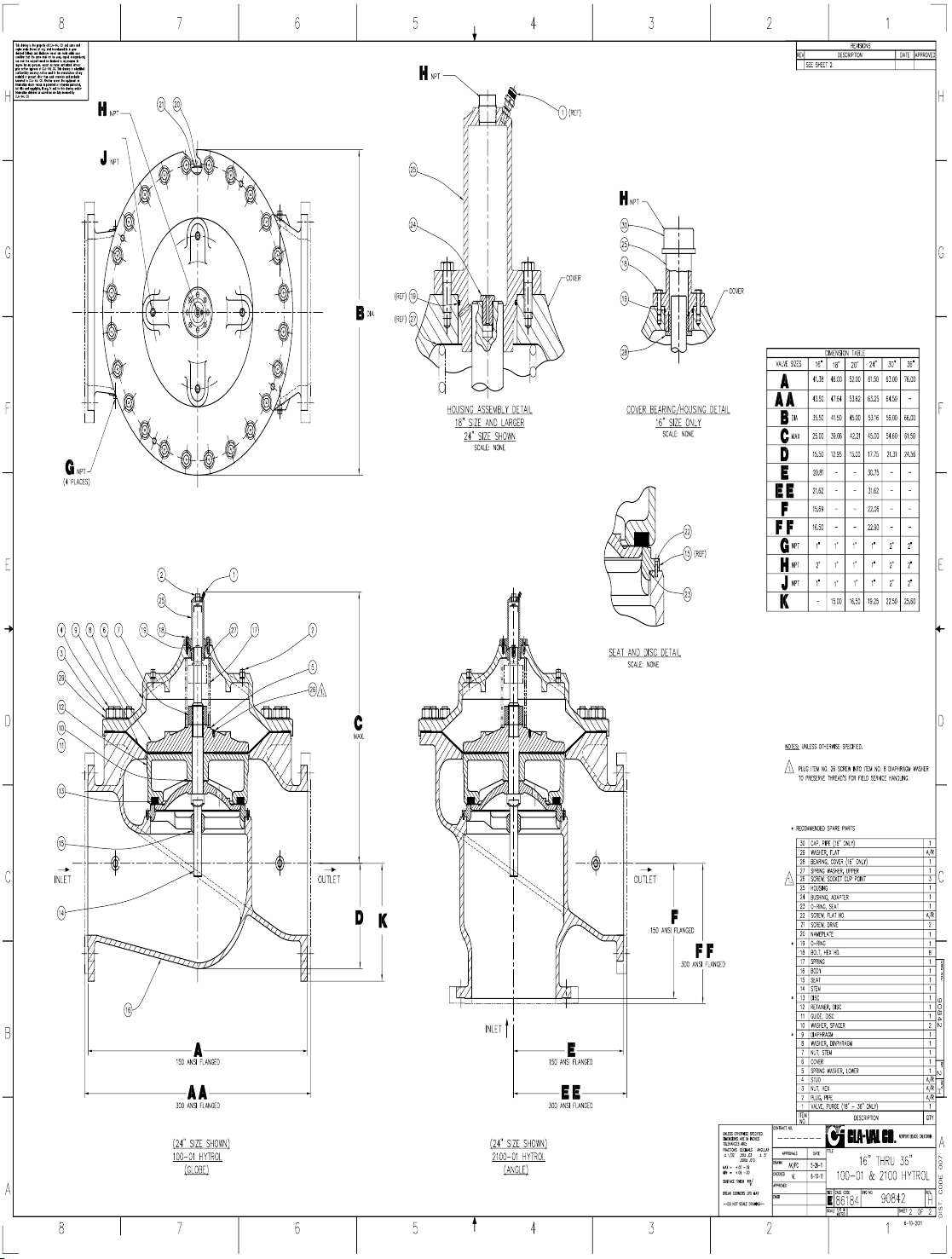
100-01
Page 2
100-01
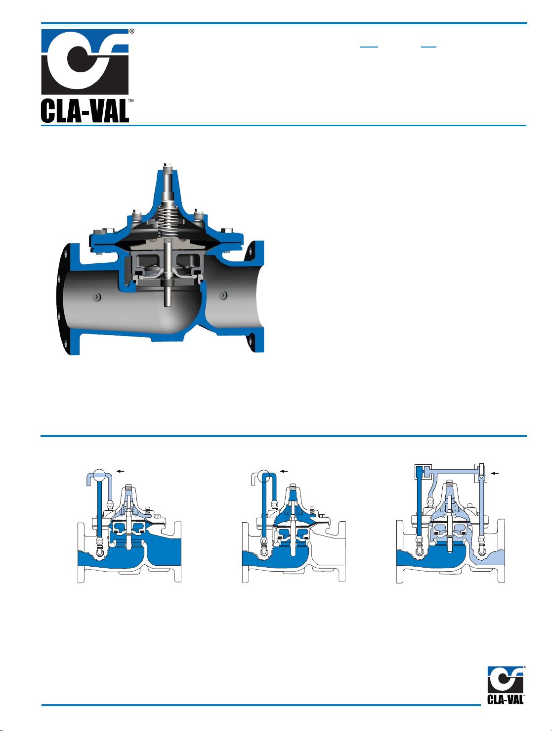
Principle of Operation
Full Open Operation
When pressure in the
cover chamber
is relieved to a zone of lower pressure, the line pressure at the valve
inlet opens the valve, allowing full
flow.
Modulating Action
The valve holds any intermediate
position when operating pressures
are equal above and below the
diaphragm. A Cla-Val “Modulating”
Pilot Control will allow the valve to
automatically compensate for line
pressure changes.
Tight Closing Operation
When pressure from the valve inlet
is applied to the cover chamber, the
valve closes drip-tight.
• Drip-Tight, Positive Seating
• Service Without Removal From Line
• Threaded, Flanged or Grooved Ends
• Globe or Angle Pattern
• 100% Factory Tested
The Cla-Val Model 100-01 Hytrol Valve is a hydraulically
operated, diaphragm actuated, globe or angle pattern
valve. It consists of three major components: body,
diaphragm assembly, and cover. The diaphragm assembly
is the only moving part.
The diaphragm assembly is guided top and bottom by a
precision machined stem. It utilizes a non-wicking
diaphragm of nylon fabric bonded with synthetic rubber. A
resilient synthetic rubber disc retained on three and one half
sides by a disc retainer forms a drip-tight seal with the renewable
seat when pressure is applied above the diaphragm.
The Model 100-01 is the basic valve used in nearly all
Cla-Val Automatic Control Valves. It is the valve of choice
for system applications requiring remote control, pressure
regulation, solenoid operation, rate of flow control, liquid
level control or check valve operation. The rugged simplicity of design and packless construction assure a long life of
dependable, trouble-free operation. It is available in various
materials and in a full range of sizes, with either threaded,
flanged or grooved ends. Its applications are unlimited.
MODEL
On-Off Control
Modulating
Control
On-Off Control
Hytrol Valve
(Sizes 3/8"-36")
Page 3
Specifications Model 100-01
Viton®Rubber Parts- suffix KB
Optional diaphragm, disc and o-ring fabricated with Viton
®
synthetic rubber. Viton®is
well suited for use with mineral acids, salt
solutions, chlorinated hydrocarbons, and
petroleum oils; and is primarily used in high
temperature applications up to 250° F.
Do
not use with epoxy coatings above
175° F.
Epoxy Coating - suffix KC
This option NSF 61 Listed and FDA
approved, fusion bonded epoxy coating is
for use with cast iron, ductile iron or steel
valves. This coating is resistant to various
water conditions, certain acids, chemicals,
solvents and alkalies.
Epoxy coatings are
applied in accordance with AWWA coating
specifications C116-03.
Do not use with temperatures above
175° F.
Dura-Kleen® Stem - suffix KD
This stem is designed for applications
where water supplies containing dissolved
minerals create deposits that build-up on a
standard stem and hamper valve operation. A patented, self-cleaning design on
the stem allows all valve sizes to operate
freely in the harshest conditions.
Delrin
®
Sleeved Stem- suffix KG
The Delrin
®
sleeved stem is designed for
applications where water supplies contain
dissolved minerals which can form
deposits that build up on the valve stem
and hamper valve operation. Scale buildup will not adhere to the Delrin
®
sleeve
stem. Delrin
®
sleeved stems are not recommended for valves in continuous operation where differential pressures are in
excess of 80 psi (2" and larger Hytr ol v al ve s) .
Heavy Spring
-
suffix KH
The heavy spring option is used in applications where there is low differential pressure across the valve, and the additional
spring force is needed to help the valve
close. This option is best suited for valves
used in on-off (non-modulating) service.
Anti-Cavitation Trim
-
suffix KO
Anti-Cavitation Trim components consist of
a stainless steel radial slotted disc guide
and seat. This system is used when high
differentials are present across the valve.
Water Treatment Clearance
-
suffix KW
This additional clearance is beneficial in
applications where water treatment compounds can interfere with the closing of the
valve. The smaller outside diameter disc
guide provides more clearance between
the disc guide and the valve seat. This
option is best suited for valves used in onoff (non-modulating) service.
For assistance in selecting appropriate valve options or valves manufactured with special design requirements, please contact
our Regional Sales Office or Factory.
Available Sizes
Pattern Threaded Flanged Grooved End
Globe3⁄8" - 3" 11⁄2" - 36" 11⁄2"-2"- 21⁄2"- 3"- 4"- 6"- 8"
Angle 1" - 3" 11⁄2" - 16" & 24" 2" - 3" - 4"
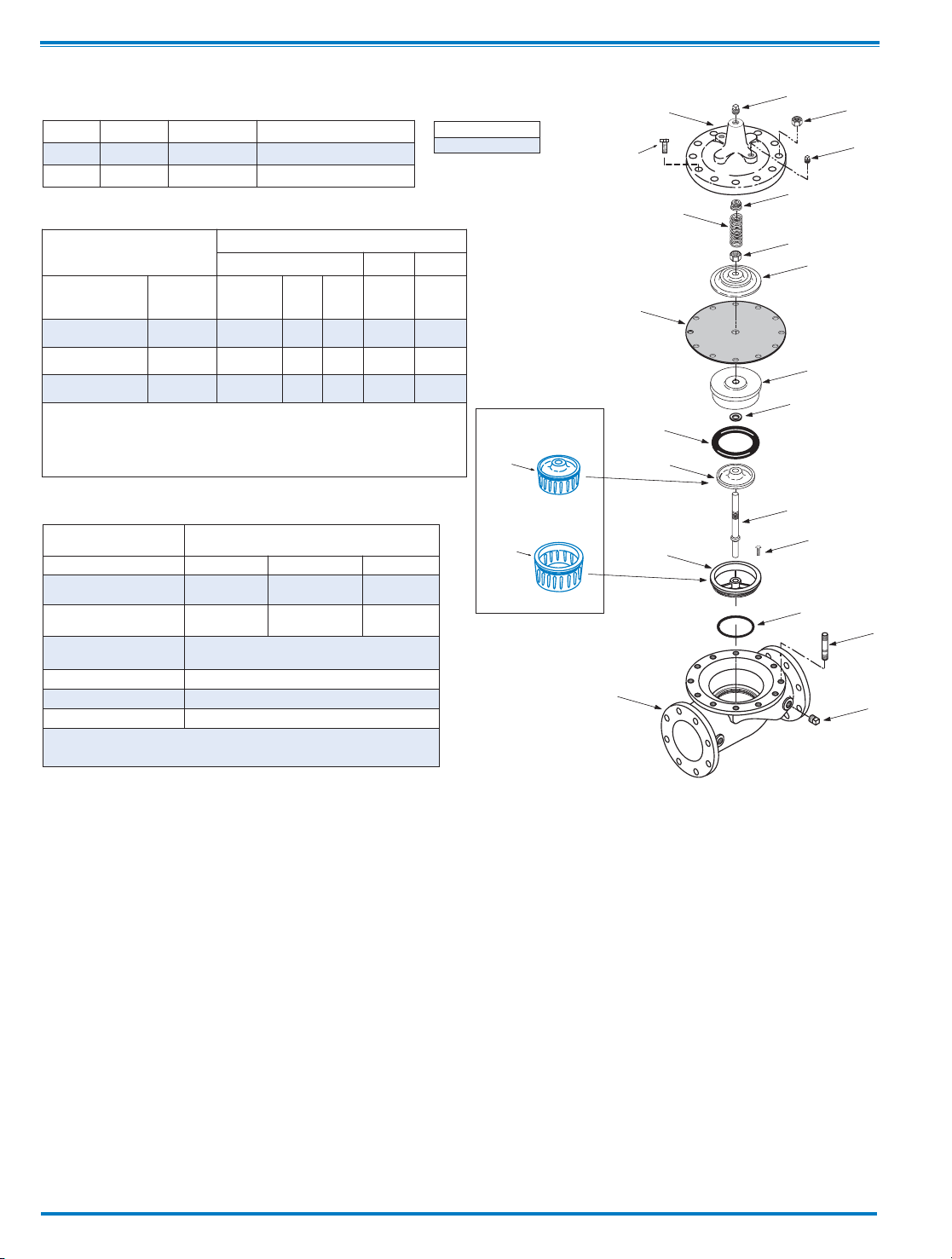
COVER
PIPE PLUG
COVER BEARING
SPRING
STEM NUT
DIAPHRAGM WASHER
DISC RETAINER
BODY
*
SPACER WASHERS
DISC GUIDE
SEAT
PIPE PLUG
STEM
SEAT O-RING
STUD
8" and Larger
*
DIAPHRAGM
*
DISC
*
Repair Parts
Seat Screw
8" and Larger
(Globe
or
Angle)
PIPE PLUG
HEX NUT
8" and Larger
Cover Bolt
6" and Smaller
KO
DISC GUIDE
KO
SEAT
KO Anti-Cavitation
Trim Option
Component Standard Material Combinations
Body & Cover Ductile Iron Cast Steel Bronze
Available Sizes 3/8" - 36" 1" - 16" 1" -16"
Disc Retainer &
Diaphragm Washer
Cast Iron Cast Steel Bronze
Trim: Disc Guide,
Seat & Cover Bearing
Bronze is Standard
Stainless Steel is optional
Disc Buna-N®Rubber
Diaphragm Nylon Reinforced Buna-N®Rubber
Stem, Nut & Spring Stainless Steel
For material options not listed, consult factory.
Cla-Val manufactures valves in more than 50 different alloys.
Materials
Valve Body & Cover
Pressure Class
Flanged Grooved Threaded
Grade Material
ANSI
Standards*
150
Class
300
Class
300
Class
End‡
Details
ASTM A536 Ductile Iron B16.42 250 400 400 400
ASTM A216-WCB Cast Steel B16.5 285 400 400 400
ASTM B62 Bronze B16.24 225 400 400 400
Note: * ANSI standards are for flange dimensions only.
Flanged valves are available faced but not drilled.
‡ End Details machined to ANSI B2.1 specifications.
Valves for higher pressure are available; consult factory for details
Pressure Ratings
(Recommended Maximum Pressure - psi)
Operating Temp. Range
Fluids
-40°to 180°F
Page 4
12
1
1/2
23 4 6810 16
2
1/2
14 24
11/4
1
1
2
34
6
810
12
24
2
1/2
11/2
14
16
11/4
3630
20
18
1/2*1*3/4*
(*Non Guided Stem)
3/8*
1
10 20 30 40 60 80 100 200 500 1000 2000 5000 10,000 20,000 50,000
1
2
3
4
6
8
10
20
30
40
60
80
100
5 3
Angle Valve Sizes (Inches)
Globe Valve Sizes (Inches)
Pressure Drop — psi
Flow Rate gpm (water)
1
100,000
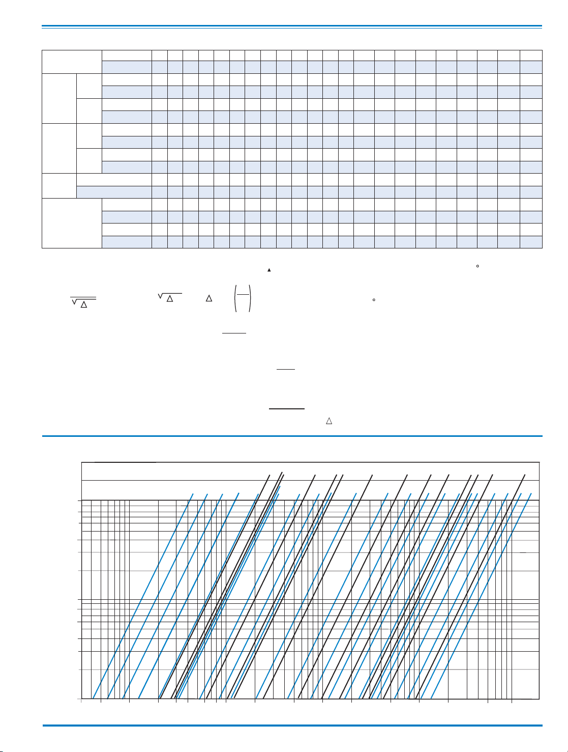
Model 100-01 Flow Chart (Based on normal flow through a wide open valve)
K =
894d
4
C
2
v
L =
K
12 f
K Factor (Resistance Coefficient)
The Value of K is calculated from the formula:
(U.S. system units)
Equivalent Length of Pipe
Equivalent lengths of pipe (L) are determined from the formula:
(U.S. system units)
Fluid Velocity
Fluid velocity can be calculated from the following formula:
(U.S. system units)
d
V =
.4085 Q
2
d
C
V
Factor
Formulas for computing C Factor, Flow (Q) and Pressure Drop
V
( P):
C
V
=
Q
P
C
V
=
Q
P
C
V
=
Q
P
2
V
Where:
U.S. (gpm) @ 1 psi differential at 60 F water
(l/s) @ 1 bar (14.5 PSIG) differential
or
at 15 C water
inside pipe diameter of Schedule 40 Steel Pipe (inches)
friction factor for clean, new Schedule 40 pipe
(dimensionless) (from Cameron Hydraulic Data,
18th Edition, P 3-119)
Resistance Coefficient (calculated)
Equivalent Length of Pipe (feet)
Flow Rate in U.S. (gpm) or (l/s)
Fluid Velocity (feet per second) or (meters per second)
Pressure Drop in (psi) or (bar)
=
=
=
=
=
=
=
=
=
P
V
Q
L
K
f
d
C
Functional Data Model 100-01
*Estimated
Valve Size
Inches
3
⁄8
†
1
⁄2
†
3
⁄4
†1†
111⁄4 11⁄2 221⁄2 3 4 6 8 10 12 14 16 18 20 24 30 36
mm.
10 15 20 25 25 32 40 50 65 80 100 150 200 250 300 350 400 450 500 600 750 900
C
V
Factor
Globe
Pattern
Gal./Min.(gpm.)
1.8 6 8.5 13.3 20 30 32 54 85 115 200 440 770 1245 1725 2300 3130 3725 5345 7655 10150 14020
Litres/Sec. (l/s.)
.43 1.44 2.04 3.2 4.8 7.2 7.7 13 20 28 48 106 185 299 414 552 752 894 1286 1837 2436 3200
Angle
Pattern
Gal./Min.(gpm.)
— — — — 21 27 29 61 101 139 240 541 990 1575 2500* 3060* 4200* — — 9950* — —
Litres/Sec. (l/s.)
— — — — 5.0 6.5 7 15 24 33 58 130 238 378 600 734 1008 — — 2388 — —
Equivalent
Length
of
Pipe
Globe
Pattern
Feet (ft.)
25 7 16 23 10 19 37 51 53 85 116 211 291 347 467 422 503 612 595 628 1181 2285
Meters (m.)
7.6 2.2 4.8 7.1 3.1 5.7 12 15.5 16 26 35 64 89 106 142 129 154 187 181 192 552 569
Angle
Pattern
Feet (ft.)
— — — — 9.0 28 46 40 37 58 80 139 176 217 222* 238* 247* — — 372* — —
Meters (m.)
— — — — 2.8 8.7 14 12 11 18 25 43 54 66 68 73 75 — — 113 — —
K
Factor
Globe Pattern
16.3 3.7 5.7 6.1 2.7 3.6 5.9 5.6 4.6 6.0 5.9 6.2 6.1 5.8 6.1 5.0 5.2 5.2 4.6 4.0 5.3 7.8
Angle Pattern
— — — — 2.5 4.4 7.1 4.4 3.3 4.1 4.1 4.1 3.7 3.6 2.9 2.8 2.6 — — 2.4 — —
Liquid Displaced
from Cover
Chamber When
Valve Opens
Fl. Oz
.12.34.34.70————————— — —————— — —
U.S. Gal.
— — — — .02 .02 .02 .03 .04 .08 .17 .53 1.26 2.51 4.0 6.5 9.6 11 12 29 42 90
ml
3.510.110.120.720.775.775.7121163303643—————————— —
Litres
— — — — — — — — — — — 2.0 4.8 9.5 15.1 24.6 36.2 41.6 45.4 109.8 197 340
† Non Guided Stem
Page 5
G
GG
GGG
D
Inlet
DD
DDD
F
FF
100-01
Threaded &
Flanged
A
E
C
(MAX)
K
J
H
Inlet
Outlet
AA
AAA
B
(Diameter)
A
E
C
(MAX)
J
Inlet Outlet
B
100-01
3/8”, 1/2”, 3/4”, 1”
Auxillary Hytrol Valves
with non Guided Stems
GGGG
DDDD
Inlet
AAAA
100-01
Grooved
EE
CC
(MAX)
K
J
H
Inlet
Outlet
B
(Diameter)
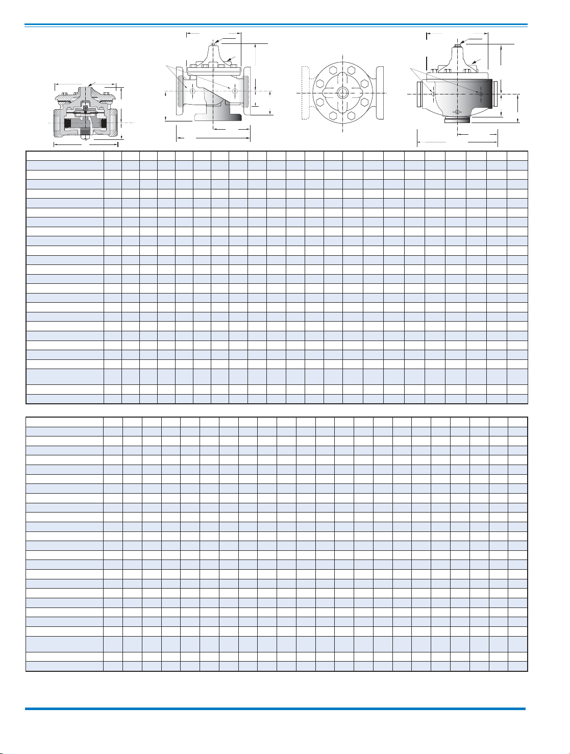
Dimensions
CLA-VAL
Copyright Cla-Val 2011 Printed in USA Specifications subject to change without notice.
P.O. Box 1325 • Newport Beach, CA 92659-0325 • Phone: 949-722-4800 • Fax: 949-548-5441 • E-mail: [email protected] • Website cla-val.com
©
E-100-01 (R-8/2011)
Note: The top two flange holes on valve size 36 are threaded to 1 1/2"-6 UNC.*Non Guided Stem Auxillary Hytrol Controls
Cla-Val Control Valves operate with maximum efficiency when mounted in horizontal piping with the main valve cover UP, however, other positions are acceptable. Due to
component size and weight of 8 inch and larger valves, installation with cover UP is advisable. We recommend isolation valves be installed on inlet and outlet for maintenance.
Adequate space above and around the valve for service personnel should be considered essential. A regular maintenance program should be established based on the specific
application data. However, we recommend a thorough inspection be done at least once a year. Consult factory for specific recommendations.
Valve Size (Inches) 3/8* 1/2* 3/4*1* 11 1/4 1 1/2 22 1/2 3468101214161820243036
A Threaded
2.75 3.50 3.50 5.12 7.25 7.25 7.25 9.38 11.00 12.50 — — — — — — — — — — — —
AA 150 ANSI
——————8.509.3811.0012.0015.0020.0025.3829.7534.0039.0041.3846.0052.0061.5063.0076.00
AAA 300 ANSI
— — — — — — 9.00 10.00 11.62 13.25 15.62 21.00 26.38 31.12 35.50 40.50 43.50 47.64 53.62 63.24 64.50 76.00
AAAA Grooved End
——————8.509.0011.0012.5015.0020.0025.38—————————
B Dia.
2.50 3.12 3.12 4.38 5.62 5.62 5.62 6.62 8.00 9.12 11.50 15.75 20.00 23.62 28.00 32.75 35.50 41.50 45.00 53.16 56.00 66.00
C Max.
2.33 5.88 5.88 6.25 5.50 5.50 5.50 6.50 7.56 8.19 10.62 13.38 16.00 17.12 20.88 24.19 25.00 39.06 41.90 43.93 54.60 61.50
CC Max. Grooved End
— — — — — — 4.75 5.75 6.88 7.25 9.31 12.12 14.62 — — — — — — — — —
D Threaded
————3.253.253.254.755.506.25— — — —————————
DD 150 ANSI
— — — — — — 4.00 4.75 5.50 6.00 7.50 10.00 12.69 14.88 17.00 19.50 20.81 — — 30.75 — —
DDD 300 ANSI
——————4.255.005.886.387.8810.5013.2515.5617.7520.2521.62— —31.62— —
DDDD Grooved End
— — — — — — — 4.75 — 6.00 7.50 — — — — — — — — — — —
E
1.25 0.88 0.88 1.63 1.12 1.12 1.12 1.50 1.69 2.06 3.19 4.31 5.31 9.25 10.75 12.62 15.50 12.95 15.00 17.75 21.31 24.56
EE Grooved End
— — — — — — 2.00 2.50 2.88 3.12 4.25 6.00 7.56 — — — — — — — — —
F 150 ANSI
——————2.503.003.503.754.505.506.758.009.5010.5011.7515.0016.5019.2522.5025.60
FF 300 ANSI
— — — — — — 3.06 3.25 3.75 4.13 5.00 6.25 7.50 8.75 10.25 11.50 12.75 15.00 16.50 19.25 24.00 25.60
G Threaded
————1.881.881.883.254.004.50— — — —————————
GG 150 ANSI
— — — — — — 4.00 3.25 4.00 4.00 5.00 6.00 8.00 8.62 13.75 14.88 15.69 — — 22.06 — —
GGG 300 ANSI
——————4.253.504.314.385.316.508.509.3114.5015.6216.50— —22.90— —
GGGG Grooved End
— — — — — — — 3.25 — 4.25 5.00 — — — — — — — — — — —
H NPT Body Tapping
—.125.125.25.375.375.375.375.50.50.75.751111111122
J NPT Cover Center Plug
.125 .125 .125 .25 .25 .25 .25 .50 .50 .50 .75 .75 1 1 1.25 1.5 2 1.5 1.5 1.5 2 2
K NPT Cover Tapping
—.125.125.25.375.375.375.375.50.50.75.751111111122
Valve Stem Internal
Thread UNF
— — — — 10-32 10-32 10-32 10-32 10-32 1⁄4-28 1⁄4-28 3⁄8-24 3⁄8-24 3⁄8-24 3⁄8-24 3⁄8-24 1⁄2-20 3⁄4-16 3⁄4-16 3⁄4-16 3⁄4-16 3⁄4-16
Stem Travel
————0.40.40.40.60.70.81.11.72.32.83.44.04.55.15.636.757.58.5
Approx. Ship Wt. Lbs.
3 3 8 8 15 15 15 35 50 70 140 285 500 780 1165 1600 2265 2982 3900 6200 7703 11720
Valve Size (mm) 10* 15* 20* 25* 25 32 40 50 65 80 100 150 200 250 300 350 400 450 500 600 750 900
A Threaded
70 89 89 130 184 184 184 238 279 318 — — — — — — — — — — — —
AA 150 ANSI
——————2162382793053815086457568649911051 1168 1321 1562 1600 1930
AAA 300 ANSI
— — — — — — 229 254 295 337 397 533 670 790 902 1029 1105 1210 1362 1606 1638 1930
AAAA Grooved End
——————216228279318381508645—————————
B Dia.
64 80 80 111 143 143 143 168 203 232 292 400 508 600 711 832 902 1054 1143 1350 1422 1676
C Max.
59 149 149 159 140 140 140 165 192 208 270 340 406 435 530 614 635 992 1064 1116 1387 1562
CC Max. Grooved End
— — — — — — 120 146 175 184 236 308 371 — — — — — — — — —
D Threaded
————838383121140159————————————
DD 150 ANSI
— — — — — — 102 121 140 152 191 254 322 378 432 495 528 — — 781 — —
DDD 300 ANSI
——————108127149162200267337395451514549——803——
DDDD Grooved End
— — — — — — — 121 — 152 191 — — — — — — — — — — —
E
32 23 23 42 29 29 29 38 43 52 81 110 135 235 273 321 394 329 381 451 541 624
EE Grooved End
— — — — — — 52 64 73 79 108 152 192 — — — — — — — — —
F 150 ANSI
——————64768995114140171203241267298381419489572650
FF 300 ANSI
— — — — — — 78 83 95 105 127 159 191 222 260 292 324 381 419 489 610 650
G Threaded
————48484883102114————————————
GG 150 ANSI
— — — — — — 102 83 102 102 127 152 203 219 349 378 399 — — 560 — —
GGG 300 ANSI
——————10289110111135165216236368397419——582——
GGGG Grooved End
— — — — — — — 83 — 108 127 — — — — — — — — — — —
H NPT Body Tapping
—.125.125.25.375.375.375.375.50.50.75.751111111122
J NPT Cover Center Plug
.125 .125 .125 .25 .25 .25 .25 .50 .50 .50 .75 .75 1 1 1.25 1.5 2 1.5 1.5 1.5 2 2
K NPT Cover Tapping
—.125.125.25.375.375.375.375.50.50.75.751111111122
Valve Stem Internal
Thread UNF
— — — — 10-32 10-32 10-32 10-32 10-32
1⁄4-28 1⁄4-28 3⁄8-24 3⁄8-24 3⁄8-24 3⁄8-24 3⁄8-24 1⁄2-20 3⁄4-16 3⁄4-16 3⁄4-16 3⁄4-16 3⁄4-16
Stem Travel
————1010
10 15 18 20 28 43 58 71 86 102 114 130 143 171 190 216
Approx. Ship Wt. Kgs.
1.4 1.4 1.4 6 7 7 7 16 23 32 64 129 227 354 528 726 1027 1353 1769 2812 3494 5316
Model 100-01
Page 6
Description
The CIa-VaI Model 100-01 Hytrol Valve is a main valve for
CIa-VaI Automatic Control Valves. It is a hydraulically operated,
diaphragm-actuated, globe or angle pattern valve.
This valve consists of three major components; body, diaphragm
assembly, and cover. The diaphragm assembly is the only
moving part. The diaphragm assembly uses a diaphragm of nylon
fabric bonded with synthetic rubber. A synthetic rubber disc,
contained on three and one half sides by a disc retainer and disc
guide, forms a seal with the valve seat when pressure is applied
above the diaphragm. The diaphragm assembly forms a sealed
chamber in the upper portion of the valve, separating operating
pressure from line pressure.
Installation
1. Before valve is installed, pipe lines should be flushed of all
chips, scale and foreign matter.
2. It is recommended that either gate or block valves be
installed on both ends of the 100-01 Hytrol Valve to facilitate
isoIating the valve for preventive maintenance and repairs.
3. Place the valve in the line with flow through the valve in the
direction indicated on the inlet nameplate. (See “Flow Direction”
Section)
4. Allow sufficient room around valve to make adjustments and
for disassembly.
5. CIa-VaI 100-01 Hytrol Valves operate with maximum e ffi ciency
when mounted in horizontal piping with the cover UP, however,
other positions are acceptable. Due to size and weight of the
cover and internal components of 8 inch and larger valves,
installation with the cover UP is advisable. This makes internal
parts readily accessible for periodic inspection.
6. Caution must be taken in the installation of this valve to insure
that galvanic and/or electrolytic action does not take place. The
proper use of dielectric fittings and gaskets are required in all
systems using dissimilar metals.
7. If a pilot control system is installed on the 100-01 Hytrol Valve,
use care to prevent damage. If it is necessary to remove fittings
or components, be sure they are kept clean and replaced
exactly as they were.
8. After the valve is installed and the system is first pressurized,
vent air from the cover chamber and pilot system tubing by
loosening fittings at all high points.
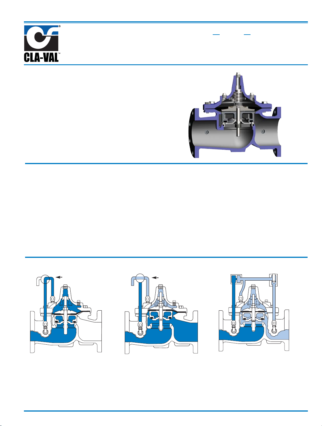
Tight Closing Operation
When pressure from the valve inlet (or
an equivalent independent operating
pressure) is applied to the diaphragm
chamber the valve closes drip-tight.
Full Open Operation
When pressure in diaphragm chamber
is relieved to a zone of lower pressure
(usually atmosphere) the line pressure
(5 psi Min.) at the valve inlet opens the
valve.
Modulating Action
Valve modulates when diaphragm pressure is held at an intermediate point
between inlet and discharge pressure.
With the use of a Cla-Val. "modulating
control," which reacts to line pressure
changes, the pressure above the
diaphragm is varied, allowing the valve
to throttle and compensate for the
change.
Principles of Operation
Three Way
Pilot Control
Three Way
Pilot Control
Restriction
Modulating
Control
100-01
Hytrol Valve
MODEL
INSTALLATION / OPERATION / MAINTENANCE
Page 7
2
Flow Direction
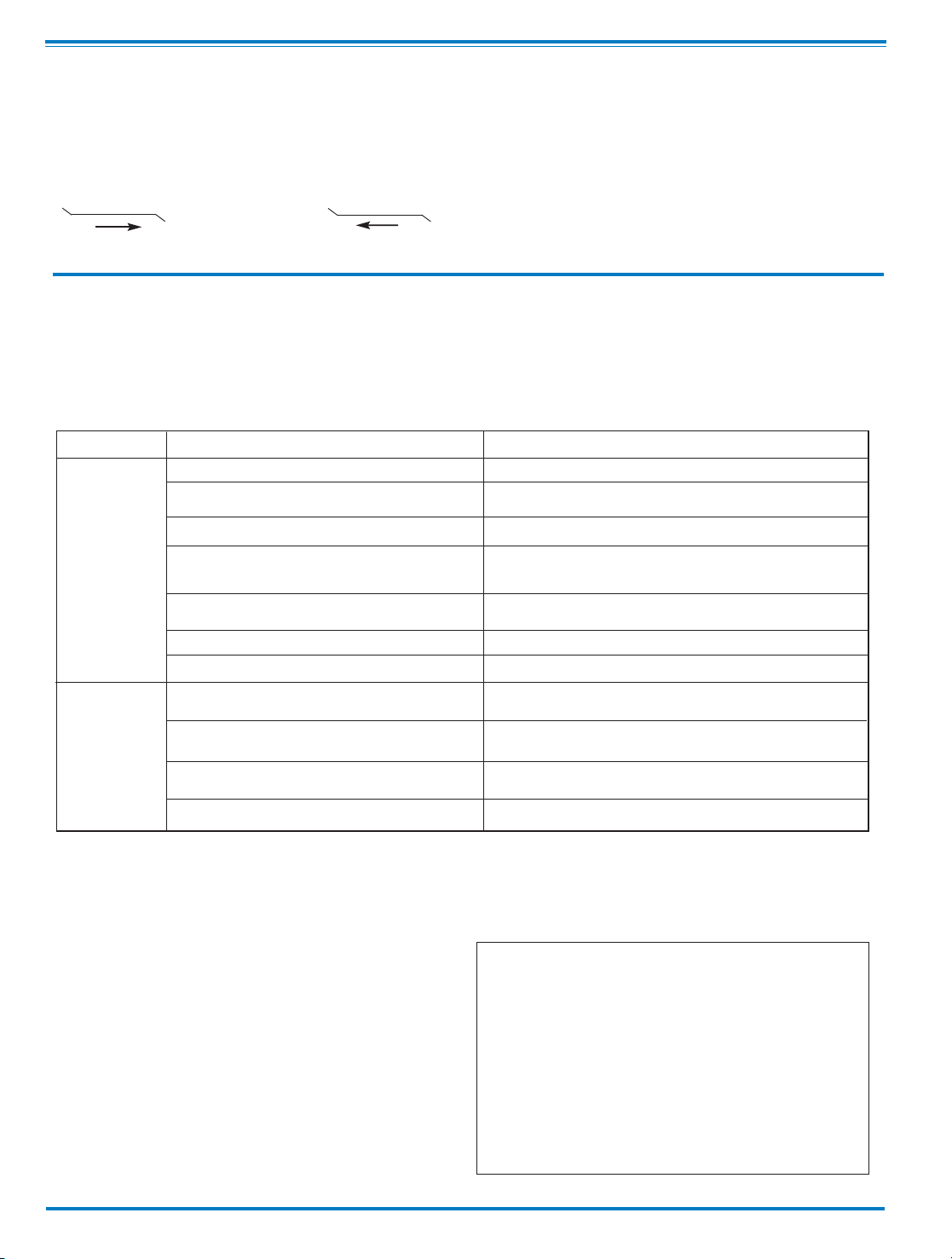
The flow through the 100-01 Hytrol Valve can be in one of two
directions. When flow is “up-and-over the seat,” it is in “normal”
flow and the valve will fail in the open position. When flow is “overthe seat-and down,” it is in “reverse” flow and the valve will fail in
the closed position. There are no permanent flow arrow markings.
The valve must be installed according to nameplate data.
BRIDGEWALL INDlCATOR
Normal Flow Reverse Flow
Troubleshooting
The following troubleshooting information deals strictly with the
Model 100-01 Hytrol Valve. This assumes that all other components of the pilot control system have been checked out and are
in proper working condition. (See appropriate sections in
Technical Manual for complete valve).
Three Checks
The 100-01 Hytrol Valve has only one moving part (the diaphragm
and disc assembly). So, there are only three major types of problems to be considered.
First: Valve is stuck - that is, the diaphragm assembly is not free
to move through a full stroke either from open to close or vice
versa.
Second: Valve is free to move and can’t close because of a worn
out diaphragm.
Third: Valve leaks even though it is free to move and the
diaphragm isn’t leaking.
Closed isolation valves in control system, or in main line.
Lack of cover chamber pressure.
Diaphragm damaged. (See Diaphragm Check.)
Diaphragm assembly inoperative.
Corrosion or excessive scale build up on valve stem.
(See Freedom of Movement Check)
Mechanical obstruction. Object lodged in valve.
(See Freedom of Movement Check)
Worn disc. (See Tight Sealing Check)
Badly scored seat. (See Tight Sealing Check)
Closed upstream and/or downstream isolation
valves in main line.
Insufficient line pressure.
Diaphragm assembly inoperative. Corrosion or excessive
buildup on valve stem. (See Freedom of Movement Check)
Diaphragm damaged. (For valves in "reverse flow" only)
After checking out probable causes and remedies, the following three checks can be used to diagnose the nature of the
problem before maintenance is started. They must be done in the order shown.
Open Isolation valves.
Check upstream pressure, pilot system, strainer, tubing, valves, or needle
valves for obstruction.
Replace diaphragm.
Clean and polish stem. Inspect and replace any damaged or badly eroded
part.
Remove obstruction.
Replace disc.
Replace seat.
Open isolation valves.
Check upstream pressure. (Minimum 5 psi flowing line pressure differential.)
Clean and polish stem. Inspect and replace any
damaged or badly eroded part.
Replace diaphragm.
Fails to Close
Fails to Open
CAUTION:
Care should be taken when doing the troubleshooting checks on
the 100-01 Hytrol Valve. These checks do require the valve to
open fully. This will either allow a high flow rate through the
valve, or the downstream pressure will quickly increase to the
inlet pressure. In some cases, this can be very harmful. Where
this is the case, and there are no block valves in the system to
protect the downstream piping, it should be realized that the
valve cannot be serviced under pressure. Steps should be
taken to remedy this situation before proceeding any further.
(cast into side of valve body)
SYMPTOM PROBABLE CAUSE REMEDY
Recommended Tools
1. Three pressure gauges with ranges suitable to the installation to be put at Hytrol inlet, outlet and cover connections.
2. Cla-Val Model X101 Valve Position Indicator. This provides visual indication of valve position without disassembly
of valve.
3. Other items are: suitable hand tools such as screwdrivers, wrenches, etc. soft jawed (brass or aluminum) vise,
400 grit wet or dry sandpaper and water for cleaning.
All trouble shooting is possible without removing the valve from the
line or removing the cover. It is highly recommended to permanently
install a Model X101 Valve Position Indicator and three gauges in
unused Hytrol inlet, outlet and cover connections.
Page 8

Diaphragm Check (#1 )
1. Shut off pressure to the Hytrol Valve by slowly closing upstream
and downstream isolation valves. SEE CAUTION.
2. Disconnect or close all pilot control lines to the valve cover and
leave only one fitting in highest point of cover open to atmosphere.
3.With the cover vented to atmosphere, slowly open upstream
isolation valve to allow some pressure into the Hytrol Valve body.
Observe the open cover tapping for signs of continuous flow. It is
not necessary to fully open isolating valve. Volume in cover chamber capacity chart will be displaced as valve moves to open position. Allow sufficient time for diaphragm assembly to shift positions. If there is no continuous flow, you can be quite certain the
diaphragm is sound and the diaphragm assembly is tight. If the
fluid appears to flow continuously this is a good reason to believe
the diaphragm is either damaged or it is loose on the stem. In
either case, this is sufficient cause to remove the valve cover and
investigate the leakage. (See “Maintenance” Section for procedure.)
Freedom of Movement Check (#2)
4. Determining the Hytrol Valve’s freedom of movement can be
done by one of two methods.
5. For most valves it can be done after completing Diaphragm
Check (Steps 1, 2, and 3). SEE CAUTION. At the end of step 3
the valve should be fully open.
6. If the valve has a Cla-Val X101 Position Indicator, observe the
indicator to see that the valve opens wide. Mark the point of maximum opening.
7. Re-connect enough of the control system to permit the application of inlet pressure to the cover. Open pilot system cock so
pressure flows from the inlet into the cover.
8. While pressure is building up in the cover, the valve should
close smoothly. There is a hesitation in every Hytrol Valve closure,
which can be mistaken for a mechanical bind. The stem will
appear to stop moving very briefly before going to the closed position. This slight pause is caused by the diaphragm flexing at a
particular point in the valve’s travel and is not caused by a
mechanical bind.
9. When closed, a mark should be made on the X101 Valve position indicator corresponding to the “closed” position. The distance
between the two marks should be approximately the stem travel
shown in chart.
10. If the stroke is different than that shown in stem travel chart
this is a good reason to believe something is mechanically restricting the stroke of the valve at one end of its travel. If the flow does
not stop through the valve when in the indicated “closed” position,
the obstruction probably is between the disc and the seat. If the
flow does stop, then the obstruction is more likely in the cover. In
either case, the cover must be removed, and the obstruction located and removed. The stem should also be checked for scale buildup. (See “Maintenance, section for procedure.)
11. For valves 6” and smaller, the Hytrol Valve’s freedom of movement check can also be done after all pressure is removed from
the valve. SEE CAUTION. After closing inlet and outlet isolation
valves and bleeding pressure from the valve, check that the cover
chamber and the body are temporarily vented to atmosphere.
Insert fabricated tool into threaded hole in top of valve stem, and
lift the diaphragm assembly manually. Note any roughness. The
diaphragm assembly should move smoothly throughout entire
valve stroke. The tool is fabricated from rod that is threaded on
one end to fit valve stem and has a “T” bar handle of some kind
on the other end for easy gripping. (See chart in Step 4 of
“Disassembly” Section.)
12. Place marks on this diaphragm assembly lifting tool when the
valve is closed and when manually positioned open. The distance
between the two marks should be approximately the stem travel
shown in stem travel chart. If the stroke is different than that
shown, there is a good reason to believe something is mechanically restricting the stroke of the valve. The cover must be
removed, and the obstruction located and removed. The stem
should also be checked for scale build-up. (See “Maintenance”
Section for procedure.)
Tight Sealing Check (#3)
13. Test for seat leakage after completing checks #1 & #2 (Steps
1 to 12). SEE CAUTION. Close the isolation valve downstream of
the Hytrol Valve. Apply inlet pressure to the cover of the valve, wait
until it closes. Install a pressure gauge between the two closed
valves using one of the two ports in the outlet side of the Hytrol.
Watch the pressure gauge. If the pressure begins to climb, then
either the downstream isolation valve is permitting pressure to
creep back, or the Hytrol is allowing pressure to go through it.
Usually the pressure at the Hytrol inlet will be higher than on the
isolation valve discharge, so if the pressure goes up to the inlet
pressure, you can be sure the Hytrol is leaking. Install another
gauge downstream of isolating valve. If the pressure between the
valves only goes up to the pressure on the isolation valve
discharge, the Hytrol Valve is holding tight, and it was just the isolation valve leaking.
STEM TRAVEL
(Fully Open to Fully Closed)
Valve Size (inches) Travel (inches)
Inches MM Inches MM
1 1/4 32 0.4 10
1 1/2 40 0.4 10
250 0.615
2 1/2 65 0.7 18
380 0.820
4 100 1.1 28
6 150 1.7 43
8 200 2.3 58
10 250 2.8 71
12 300 3.4 86
14 350 4.0 100
16 400 4.5 114
20 500 5.6 143
24 600 6.7 165
30 800 7.5 190
36 900 8.5 216
COVER CHAMBER CAPACITY
(Liquid Volume displaced when valve opens)
Valve size (inches) Displacement
Gallons Liters
1 1/4 .020 .07
1 1/2 .020 .07
2 .032 .12
2 1/2 .043 .16
3 .080 .30
4 .169 .64
6 .531 2.0
8 1.26 4.8
10 2.51 9.5
12 4.00 15.1
14 6.50 24.6
16 9.57 36.2
20 12.00 45.4
24 29.00 109.8
30 42.00 197.0
36 90.00 340.0
3
Page 9
Maintenance
Preventative Maintenance
The Cla-Val Co. Model 100-01 Hytrol Valve requires no lubrication or
packing and a minimum of maintenance. However, a periodic inspection schedule should be established to determine how the operating
conditions of the system are affecting the valve. The effect of these
actions must be determined by inspection.
Disassembly
Inspection or maintenance can be accomplished without removing
the valve from the line. Repair kits with new diaphragm and disc are
recommended to be on hand before work begins.
WARNING: Maintenance personnel can be injured and equipment
damaged if disassembly is attempted with pressure in the valve. SEE
CAUTION.
1. Close upstream and downstream isolation valves and independ-
ent operating pressure when used to shut off all pressure to the
valve.
2. Loosen tube fittings in the pilot system to remove pressure from
valve body and cover chamber. After pressure has been released
from the valve, use care to remove the controls and tubing. Note and
sketch position of tubing and controls for re-assembly. The schematic in front of the Technical Manual can be used as a guide when
reassembling pilot system.
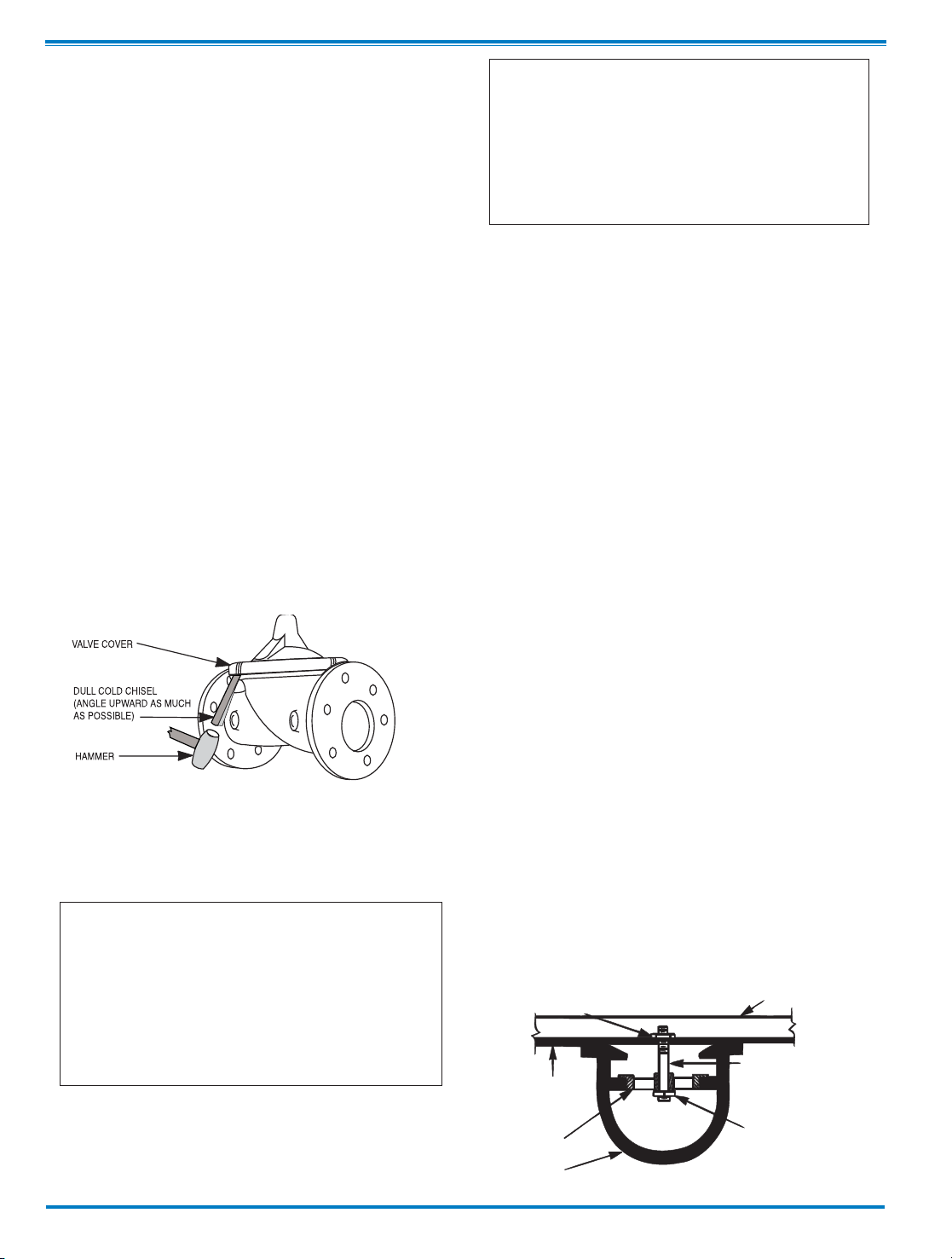
3. Remove cover nuts and remove cover. If the valve has been in
service for any length of time, chances are the cover will have to be
loosened by driving upward along the edge of the cover with a dull
cold chisel.
On 6” and smaller valves block and tackle or a power hoist can be
used to lift valve cover by inserting proper size eye bolt in place of
the center cover plug. on 8” and larger valves there are 4 holes (5/8”
— 11 size) where jacking screws and/or eye bolts may be inserted
for lifting purposes. Pull cover straight up to keep from damaging
the integral seat bearing and stem.
4. Remove the diaphragm and disc assembly from the valve body.
With smaller valves this can be accomplished by hand by pulling
straight up on the stem so as not to damage the seat bearing.
On large valves, an eye bolt of proper size can be installed in the
stem and the diaphragm assembly can be then lifted with a block and
tackle or power hoist. Take care not to damage the stem or bearings.
The valve won't work if these are damaged.
5. The next item to remove is the stem nut. Examine the stem
threads above the nut for signs of mineral deposits or corrosion.
If the threads are not clean, use a wire brush to remove as much
of the residue as possible. Attach a good fitting wrench to the nut
and give it a sharp “rap” rather than a steady pull. Usually
several blows are sufficient to loosen the nut for further removal.
On the smaller valves, the entire diaphragm assembly can be held
by the stem in a vise equipped with soft brass jaws before
removing the stem nut.
The use of a pipe wrench or a vise without soft brass jaws scars
the fine finish on the stem. No amount of careful dressing can
restore the stem to its original condition. Damage to the finish of
the stem can cause the stem to bind in the bearings and the valve
will not open or close.
6. After the stem nut has been removed, the diaphragm assembly
breaks down into its component parts. Removal of the disc from
the disc retainer can be a problem if the valve has been in service for a long time. Using two screwdrivers inserted along the outside edge of the disc usually will accomplish its removal. Care
should be taken to preserve the spacer washers in water, particularly if no new ones are available for re-assembly.
7. The only part left in the valve body is the seat which ordinarily
does not require removal. Careful cleaning and polishing of inside
and outside surfaces with 400 wet/dry sandpaper will usually
restore the seat’s sharp edge. If, however, it is badly worn and
replacement is necessary, it can be easily removed.
Seats in valve sizes 1 1/4” through 6” are threaded into the valve
body. They can be removed with accessory X109 Seat Removing
Tool available from the factory. On 8” and larger valves, the seat
is held in place by flat head machine screws. Use a tight-fitting,
long shank screwdriver to prevent damage to seat screws. If upon
removal of the screws the seat cannot be lifted out, it will be necessary to use a piece of angle or channel iron with a hole drilled
in the center. Place it across the body so a long stud can be inserted through the center hole in the seat and the hole in the angle
iron. By tightening the nut a uniform upward force is exerted on
the seat for removal.
NOTE: Do not lift up on the end of the angle iron as this may force
the integral bearing out of alignment, causing the stem to bind.
VALVE STEM THREAD SIZE
Valve Size Thread Size (UNF Internal)
1 1/4"
—2 1/2" 10—32
3"—4" 1/4—28
6"—14" 3/8—24
16" 1/2—20
20 3/4-16
24" 3/4-16
30” 3/4-16
36” 3/4-16
COVER CENTER PLUG SIZE
Valve Size Thread Size (NPT)
1 1/4"
—1 1/2" 1/4"
2"—3" 1/2"
4"—6" 3/4"
8"—10" 1"
12" 1 1/4"
14" 1 1/2"
16" 2"
20” & 24" 2"
30” & 36” 2”
NUT
ANGLE OR CHANNEL IRON
LONG STUD OR BOLT
NUT OR BOLT HEAD
DO NOT
LIFT
VALVE SEAT
VALVE BODY
4
Page 10

Lime Deposits
One of the easiest ways to remove lime deposits from the valve
stem or other metal parts is to dip them in a 5-percent muriatic
acid solution just long enough for the deposit to dissolve. This
will remove most of the common types of deposits. CAUTlON:
USE EXTREME CARE WHEN HANDLING ACID. Rinse parts in
water before handling. If the deposit is not removed by acid, then
a fine grit (400) wet or dry sandpaper can be used with water.
Reassembly
1. Reassembly is the reverse of the disassembly procedure. If a
new disc has been installed, it may require a different number of
spacer washers to obtain the right amount of “grip” on the disc.
When the diaphragm assembly has been tightened to a point
where the diaphragm cannot be twisted, the disc should be compressed very slightly by the disc guide. Excessive compression
should be avoided. Use just enough spacer washers to hold the
disc firmly without noticeable compression.
2. MAKE SURE THE STEM NUT IS VERY TIGHT. Attach a good
fitting wrench to the nut and give it a sharp “rap” rather than a
steady pull. Usually several blows are sufficient to tighten the
stem nut for final tightening. Failure to do so could allow the
diaphragm to pull loose and tear when subjected to pressure.
Test Procedure After Valve Assembly
There are a few simple tests which can be made in the field to
make sure the Hytrol Valve has been assembled properly. Do
these before installing pilot system and returning valve to
service. These are similar to the three troubleshooting tests.
1. Check the diaphragm assembly for freedom of movement
after all pressure is removed from the valve. SEE CAUTlON.
Insert fabricated tool into threaded hole in top of valve stem, and
lift the diaphragm assembly manually. Note any roughness,
sticking or grabbing. The diaphragm assembly should move
smoothly throughout entire valve stroke. The tool is fabricated
from rod that is threaded on one end to fit valve stem (See chart
in Step 4 of “Disassembly” section.) and has a “T” Bar handle of
some kind on the other end for easy gripping.
Place marks on this diaphragm assembly lifting tool when the
valve is closed and when manually positioned open. The distance between the two marks should be approximately the stem
travel shown in stem travel chart. (See “Freedom of Movement
Check” section.) If the stroke is different than that shown, there
is a good reason to believe something is mechanically restricting
the stroke of the valve. The cover must be removed, the obstruction located and removed. (See “Maintenance” Section for
procedure.)
Inspection of Parts
After the valve has been disassembled, each part should be
examined carefully for signs of wear, corrosion, or any other
abnormal condition. Usually, it is a good idea to replace the rubber parts (diaphragm and disc) unless they are free of signs of
wear. These are available in a repair kit. Any other parts which
appear doubtful should be replaced. WHEN ORDERlNG
PARTS, BE SURE TO GIVE COMPLETE NAMEPLATE DATA,
ITEM NUMBER AND DESCRlPTlON.
NOTE: If a new disc isn’t available, the existing disc can be
turned over, exposing the unused surface for contact with the
seat. The disc should be replaced as soon as practical.
3. Carefully install the diaphragm assembly by lowering the stem
through the seat bearing. Take care not to damage the stem or
bearing. Line up the diaphragm holes with the stud or bolt holes
on the body. on larger valves with studs, it may be necessary to
hold the diaphragm assembly up part way while putting the
diaphragm over the studs.
4. Put spring in place and replace cover. Make sure diaphragm
is Iying smooth under the cover.
5. Tighten cover nuts firmly using a cross-over pattern until all
nuts are tight.
6. Test Hytrol Valve before re-installing pilot valve system.
Due to the weight of the diaphragm assembly this procedure is
not possible on valves 8” and larger. on these valves, the same
determination can be made by carefully introducing a low
pressure-less than five psi) into the valve body with the cover
vented. SEE CAUTION. Looking in cover center hole see the
diaphragm assembly lift easily without hesitation, and then
settle back easily when the pressure is removed.
2. To check the valve for drip-tight closure, a line should be
connected from the inlet to the cover, and pressure applied at the
inlet of the valve. If properly assembled, the valve should hold
tight with as low as ten PSI at the inlet. See “Tight Sealing
Check” section.)
3. With the line connected from the inlet to the cover, apply full
working pressure to the inlet. Check all around the cover for any
leaks. Re-tighten cover nuts if necessary to stop leaks past the
diaphragm.
4. Remove pressure, then re-install the pilot system and tubing
exactly as it was prior to removal. Bleed air from all high
points.
5. Follow steps under “Start-Up and Adjustment” Section in
Technical Manual for returning complete valve back to service
.
5
Page 11
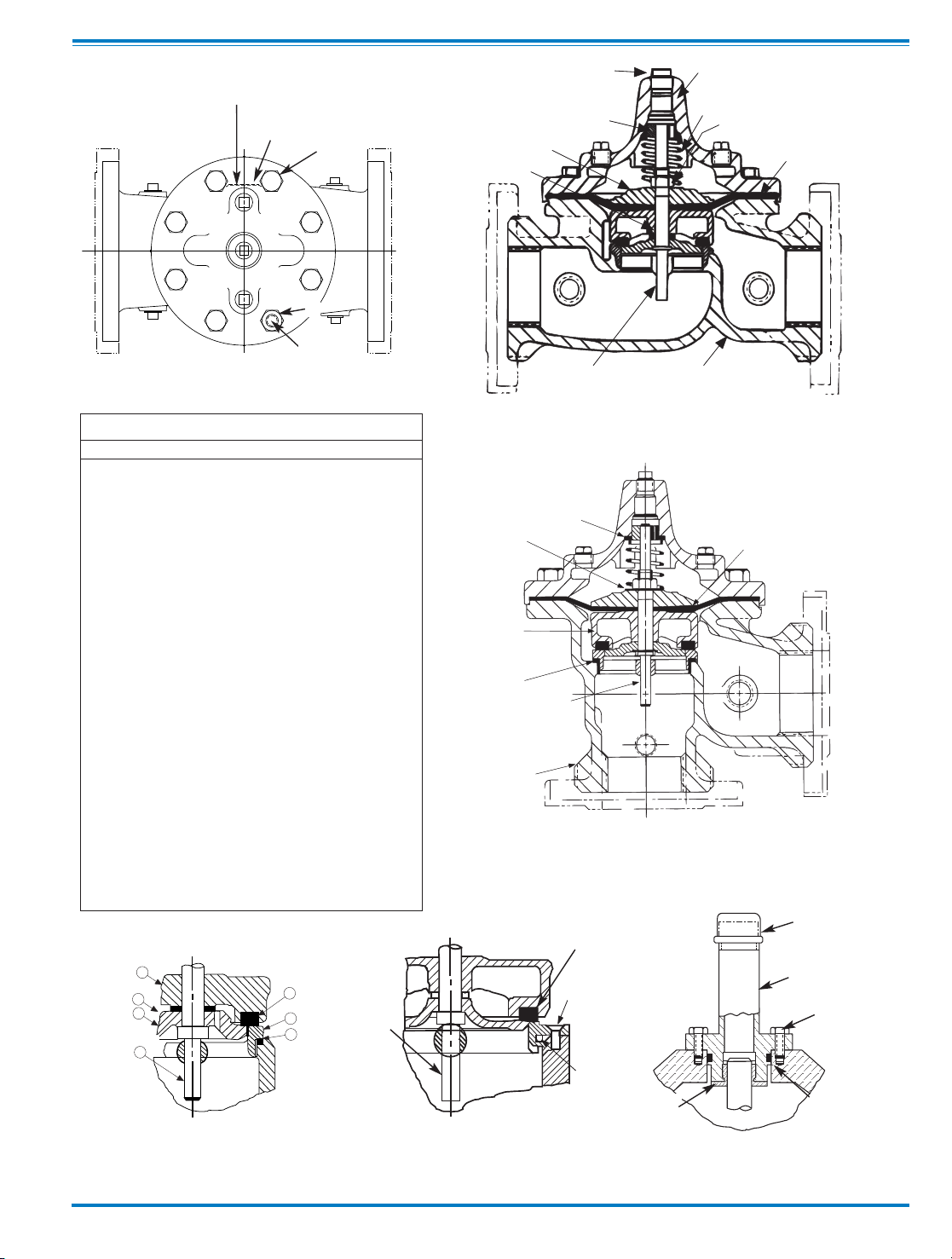
1
5
8
10
14
16
6
17
7
9
OUTLE
T
INLET
GLOBE PATTERN
9
26
27
12
15
14
16
INLET
OUTLET
ANGLE PATTERN
22
23
13
12
14
10
11
15
23
TOP VIEW
8" - 24" SEAT DETAIL
1 1/4" - 6" SEAT DETAIL
16" COVER DETAIL
4
24
2
25
13
31
28
30
29
5
14
3
Item Description
1. Pipe Plug
2. Drive Screws (for nameplate)
3. Hex Nut (8” and larger)
4. Stud (8” and larger)
5. Cover Bearing
6. Cover
7. Stem Nut
8. Diaphragm Washer
9. Diaphragm
10. Spacer Washers
11. Disc Guide
12. Disc Retainer
13. Disc
14. Stem
15. Seat
16. Body
17. Spring
22. Flat Head Screws (8” and larger)
23. Seat O-Ring
24. Hex head Bolt (1 1/4” thru 4”)
25. Nameplate
26. Upper Spring Washer (Epoxy coated valves only)
27. Lower Spring Washer (Epoxy coated valves only)
28. Cover Bearing Housing (16” only)
29. Cover O-Ring (16’” only)
30. Hex Bolt (16” only)
31. Pipe Cap (16” only)
PARTS LIST
6
Page 12
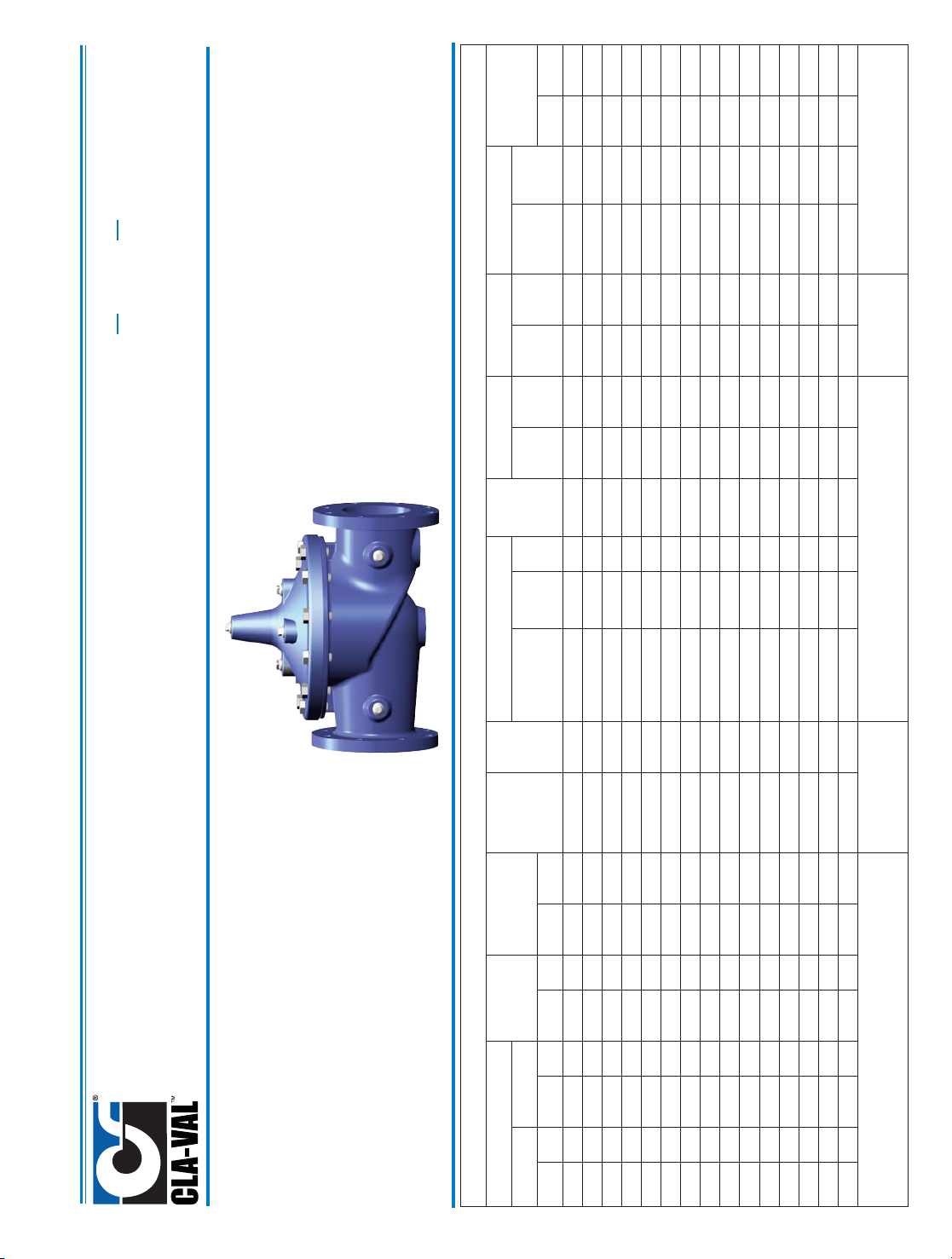
100-01
Hytrol Valve Service Data
MODEL
INSTALLATION / OPERATION / MAINTENANCE
Description 100-01 Hytrol Valve
The CIa-VaI Model 100-01 Hytrol Valve is a main valve for
CIa-VaI Automatic Control Valves. It is a hydraulically operated,
diaphragm-actuated, globe or angle pattern valve.
This valve consists of three major components; body, diaphragm
assembly, and cover. The diaphragm assembly is the only
moving part. The diaphragm assembly uses a diaphragm of nylon
fabric bonded with synthetic rubber. A synthetic rubber disc,
contained on three and one half sides by a disc retainer and disc
guide, forms a seal with the valve seat when pressure is applied
above the diaphragm. The diaphragm assembly forms a sealed
chamber in the upper portion of the valve, separating operating
pressure from line pressure.
Description 100-20 600 Series Hytrol Valve
The CIa-VaI Model 100-20 Hytrol Valve (600 Series main valve)
have only one part -the body- that is different from standard 100
Series Cla-Val main valve parts. The remaining parts of the 600
series main valve are standard Cla-Val main valve parts. All serv-
ice and maintenance information for the standard 100 Series
main valves also apply to the 600 series main valves.
The most important thing to remember when ordering main
valve repair kits and replacement parts, except for the body, all
other parts are going to be for a smaller size main valve. Cla-
Val identifies main valve parts with the flange size of the stan-
dard 100 Series main valve. Refer to the "Main Valve Sizes”
chart below.
HYTROL Service Data
HYTROL SIZE
Stem
Travel
Cover Capacity
Displacement
Valve Stem
Thread
UNF-Internal
Cover
Center
Plug
NPT
Cover Nut or Bolt
Cover
Lifting
Holes
UNC
Cover Plug Cover Torque
Stem Nut**
Stem Nut Torque
(ft. Lbs.)
100-01
100-20
Thread
(Bolt)
Socket
Qty Thread
Socket ft. Lbs. in. Lbs.
Thread
Socket
(Long)
inches mm inches mm inches mm
Gallons
Liters
Lubed DRY
1"
25 0.3 8 1/4"
1/4" - 20 (B)
7/16" 8
4
48 3/8" - 24
4
6
1 1/4"
32
0.4
10
0.020
0.07
10 - 32
1/4" 5/16" - 18 (B) 1/2"
8
8 96 7/16" -20 6 10
1 1/2" 40 0.4 10 0.020 0.07
10 - 32
1/4" 5/16" - 18 (B) 1/2"
8
8 96 7/16" -20 6 10
2" 50 0.6 15 0.032
0.12 10 - 32
1/2" 3/8" - 16 (B) 9/16" 8 3/8" 7/16" 12
1/2" - 20
3/4" 10 15
2 1/2"
65 0.7 18
0.043 0.16
10 - 32
1/2" 7/16" - 14 (B) 5/8" 8 1/2" 9/16" 20
5/8" - 18 15/16" 21
30
3" 80 4" 100 0.8
20
0.080 0.30
1/4 - 28 1/2"
1/2" - 13 (B)
3/4" 8 1/2" 9/16" 30 5/8" - 18
15/16"
21 30
4" 100 6" 150 1.1 23
0.169 0.64
1/4 - 28 3/4"
3/4" - 10 (B)
1 1/8" 8 3/4" 5/8" 110 3/4" - 16
1 1/16"
40
60
6" 150 8" 200 1.7 43 0.531 2.00 3/8 - 24 3/4"
3/4" - 10 (B) 1 1/8"
12 3/4"
5/8" 11 0
7/8" - 14
1 5/16"
85 125
8"
200 10"
250
2.3 58
1.26 4.80 3/8 - 24
1"
3/4" - 10
1 1/4" 16 5/8" - 11
1" 13/16" 110
1 1/8" -12 1 13/16"
125
185
10" 250 12" 300 2.8 71 2.51 9.50
3/8 - 24
1" 7/8" - 9 1 7/16"
20
3/4" - 10
1"
13/16" 160 1 1/2" -12 1 7/8" 252 375
12" 300 16" 400 3.4 86 4.0 15.10
3/8 - 24
1 1/4" 1 1/8" - 7 1 13/16"
20
3/4" - 10
1" 13/16" 390 1 1/2" -12 2 1/2" 270 400
14" 350 3.9
99
6.5
24.60
3/8 - 24 1 1/2" 1 1/4" - 7
2" 20
1" - 8
1" 13/16" 545 1 1/2" -12
2 1/2"
280 420
16"
400
20", 24"
600
4.5
114
9.6 36.20
1/2 - 20
2" 1 1/4" - 7
2" 20
1" - 8
1" 13/16" 545 2" - 16 3" 500 750
20" 500 5.63
143
12 45.40
3/4 - 16 1 1/2" 1 3/8" - 6
2 1/8" 24
1" - 8
1" 13/16" 670
2 1/4" - 16
3 1/2" 930
N/R
24" 600
30"
800 6.75 165
29.0
108.80 3/4 - 16*
3/4"
1 1/2" - 12 2 3/8" 24
1 1/8"- 7
1" 13/16"
800
3" - 12
Special
1350
N/R
* Adapter
p/n 2594101E
inside 1/4" - 28"
Grade 5 Bolts
"Heavy" Grade Nuts
Tighten cover nuts in a "star" cross-over pattern
** Must Use ONLY
Cla-Val Supplied part
Page 13
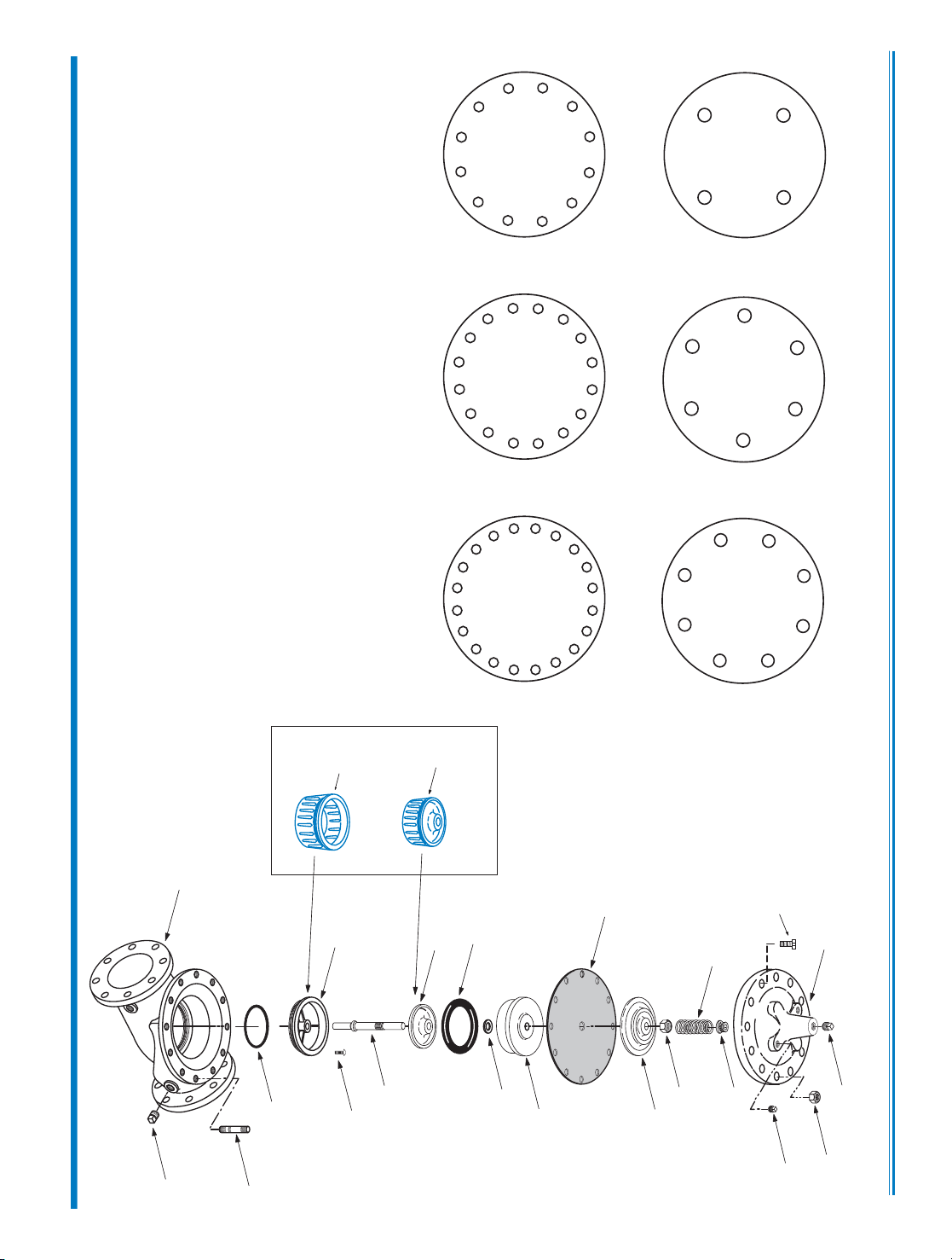
COVER
PIPE PLUG
COVER BEARING
SPRING
STEM NUT
DIAPHRAGM WASHER
DISC RETAINER
BODY
*
SPACER WASHERS
DISC GUIDE
SEAT
PIPE PLUG
STEM
SEAT O-RING
STUD
8" and Larger
*
DIAPHRAGM
*
DISC
*
Repair Parts
Seat Screw
8" and Larger
(Globe
or
Angle)
PIPE PLUG
HEX NUT
8" and Larger
Cover Bolt
6" and Smaller
KO
DISC GUIDE
KO
SEAT
KO Anti-Cavitation
Trim Option
N-100-01 (R-3/2011
CLA-VAL
Copyright Cla-Val 2011 Printed in USA Specifications subject to change without notice.
P.O. Box 1325 • Newport Beach, CA 92659-0325 • Phone: 949-722-4800 • Fax: 949-548-5441 • E-mail: [email protected] • Website cla-val.com
©
BOLT/NUT TORQUING PROCEDURES ON VALVE COVERS
4
BOLTS
6
BOLTS
8
BOLTS
12
BOLTS
16
BOLTS
20
BOLTS
4
3
2
1
65
4
3
2
1
8
7
6
5
4
3
2
1
0
9
8
7
6
5
4
3
2
1
12
11
10
9
8
7
6
5
4
3
2
1
16
15
14
13
12
11
10
9
8
7
6
5
4
3
2
1
20
19
18
17
16
15
14
13
12
11
Follow this procedure when reassembling MAIN Valve:
1. Tightens bolts/nuts in a “Star” or “Cross-Over” pattern following the
numbers shown above to insure that cover seats evenly on the diaphragm
material and body.
2. Torque the bolt/nuts in three stages with a "Star" or "Cross-Over" pattern
for each stage:
A. To approximately 10% of final torque.
B. To approximately 75% of final torque.
C. To final required torque.
3. Valves that are to be tested to 375 PSI or higher should be retorqued
after 24 hours.
100-01 Hytrol Main Valve Assembly
Page 14
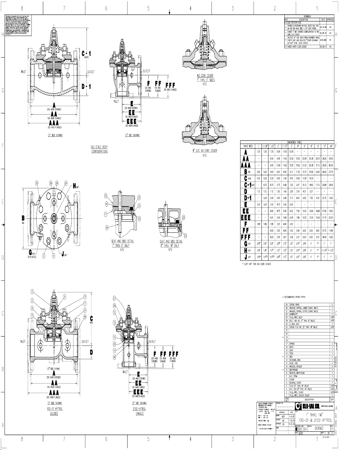
Page 15
Page 16
Cla-Val Product
Identification
Proper Identification
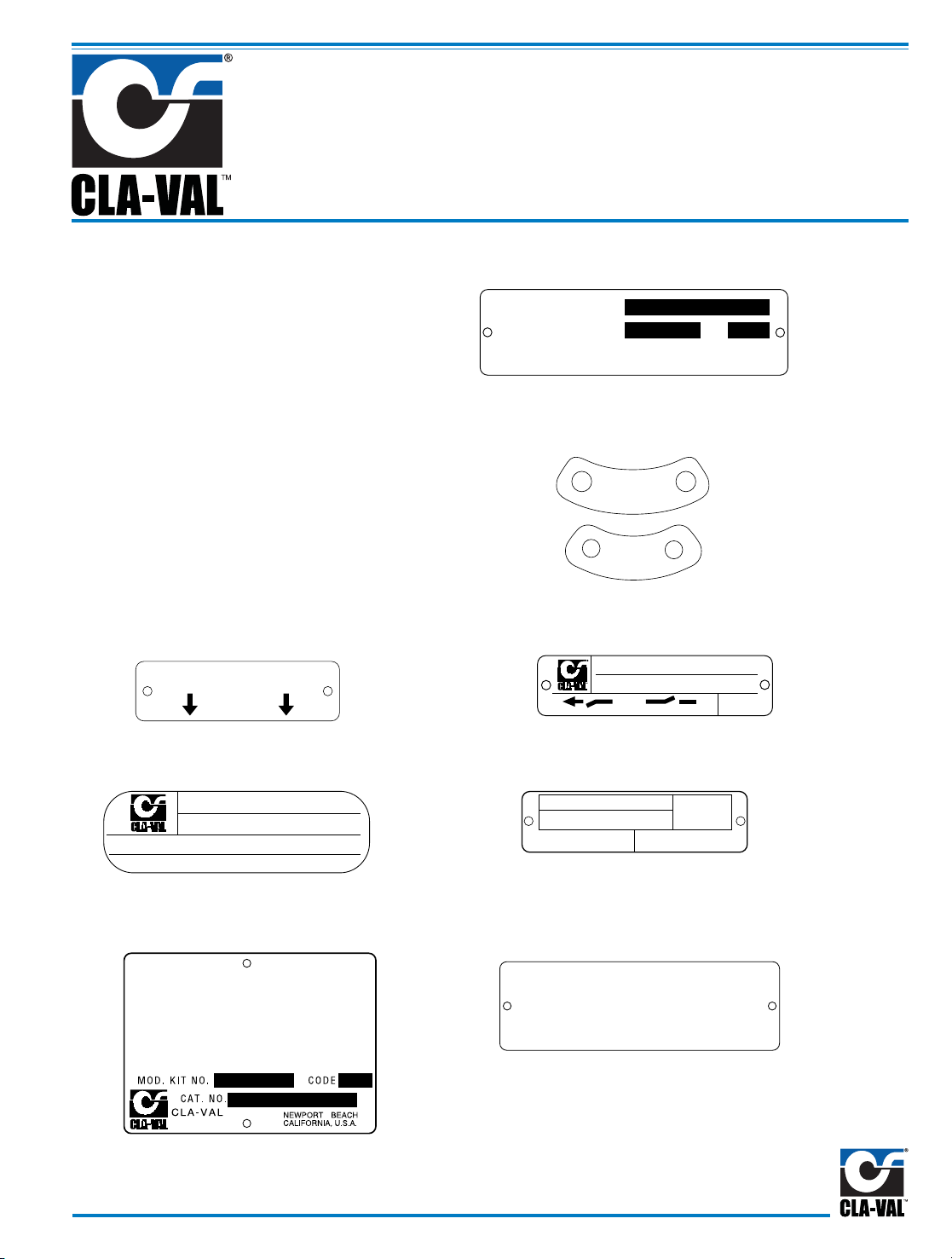
For ordering repair kits, replacement parts, or for
inquiries concerning valve operation, it is important to
properly identify Cla-Val products already in service
by including all nameplate data with your inquiry.
Pertinent product data includes valve function, size,
material, pressure rating, end details, type of pilot
controls used and control adjustment ranges.
Identification Plates
For product identification, cast-in body markings are
supplemented by identification plates as illustrated on
this page. The plates, depending on type and size of
product, are mounted in the most practical position. It
is extremely important that these identification
plates are not painted over, removed, or in any
other way rendered illegible.
INLET
EINTRITT
ENTREE
ENTRADA
SIZE &
CAT NO.
STOCK
NO.
CODE
MFD. BY CLA-VAL
NEWPORT BEACH, CALIF, U.S.A.
RESERVOIR
END
I
N
L
E
T
I
N
L
E
T
SIZE &
CAT NO.
STOCK
NO.
FLOW
MFD. BY CLA-VAL NEWPORT BEACH, CALIF. U.S.A.
CODE
C
®
™
SIZE &
CAT NO.
STOCK
NO.
SPRING
RANGE
MFD. BY CLA-VAL NEWPORT BEACH, CALIF. U.S.A.
SIZE &
CAT NO.
STOCK
NO.
CODE
MFD. BY CLA-VAL
NEWPORT BEACH, CALIF.
U.S.A.
C
®
™
DO NOT REMOVE
THIS VALVE HAS BEEN MODIFIED
SINCE ORIGINAL SHIPMENT FROM
FACTORY. WHEN ORDERING PARTS
AND/ OR SERVICE SUPPLY DATA FROM
THIS PLATE & ALL OTHER PLATES ON
ORIGINAL VALVE.
REDUCED PRESSURE BACKFLOW PREVENTION DEVICE
STK.
NO.
SER.
NO.
CAT.
NO.
RP
-4
CLA-VAL
NEWPORT BEACH, CA.
This brass plate appears on valves sized 21/2" and larger
and is located on the top of the inlet flange.
These two brass plates appear on 3/8", 1/2", and 3/4" size
valves and are located on the valve cover.
These two brass plates appear on threaded valves
1" through 3" size or flanged valves 1" through 2".
It is located on only one side of the valve body.
This brass plate appears on altitude valves only and is
found on top of the outlet flange.
This brass plate is used to identify pilot control valves.
The adjustment range is stamped into the plate.
This tag is affixed to the cover of the pilot control valve.
The adjustment range appears in the spring range section.
This aluminum plate is included in pilot system
modification kits and is to be wired to the new pilot
control system after installation.
This brass plate is used on our backflow prevention
assemblies. It is located on the side of the Number Two
check (2" through 10"). The serial number of the
assembly is also stamped on the top of the inlet flange of
the Number One check.
How to Order
Page 17
HOW TO ORDER
Because of the vast number of possible configurations and
combinations available, many valves and controls are not
shown in published product and price lists. For ordering
information, price and availability on product that are not listed,
please contact your local Cla-Val office or our factory office
located at:
SPECIFY WHEN ORDERING
• Model Number • Valve Size
• Globe or Angle Pattern • Threaded or Flanged
• Adjustment Range • Body and Trim Materials
(As Applicable) • Optional Features
• Pressure Class
UNLESS OTHERWISE SPECIFIED
• Globe or angle pattern are the same price
• Ductile iron body and bronze trim are standard
• X46 Flow Clean Strainer or X43 “Y” Strainer are included
• CK2 Isolation Valves are included in price on 4" and larger
valve sizes (6" and larger on 600 Series)
P. O. Box 1325
Newport Beach, California 92659-0325
(949) 722-4800
FAX (949) 548-5441
LIMITED WARRANTY
Automatic valves and controls as manufactured by Cla-Val are warranted
for three years from date of shipment against manufacturing defects in
material and workmanship that develop in the service for which they are
designed, provided the products are installed and used in accordance
with all applicable instructions and limitations issued by Cla-Val.
Electronic components manufactured by Cla-Val are warranted for one
year from the date of shipment.
We will repair or replace defective material, free of charge, that is returned
to our factory, transportation charges prepaid, if upon inspection, the
material is found to have been defective at time of original shipment. This
warranty is expressly conditioned on the purchaser’s providing written
notification to Cla-Val immediate upon discovery of the defect.
Components used by Cla-Val but manufactured by others, are warranted
only to the extent of that manufacturer’s guarantee.
This warranty shall not apply if the product has been altered or repaired by
others, Cla-Val shall make no allowance or credit for such repairs or
alterations unless authorized in writing by Cla-Val.
DISCLAIMER OF WARRANTIES AND
LIMITATIONS OF LIABILITY
The foregoing warranty is exclusive and in lieu of all other
warranties and representations, whether expressed, implied, oral or
written, including but not limited to any implied warranties or
merchantability or fitness for a particular purpose. All such other
warranties and representations are hereby cancelled.
Cla-Val shall not be liable for any incidental or consequential loss,
damage or expense arising directly or indirectly from the use of the
product. Cla-Val shall not be liable for any damages or charges for
labor or expense in making repairs or adjustments to the product.
Cla-Val shall not be liable for any damages or charges sustained in
the adaptation or use of its engineering data and services. No
representative of Cla-Val may change any of the foregoing or
assume any additional liability or responsibility in connection with
the product. The liability of Cla-Val is limited to material
replacements F.O.B. Newport Beach, California.
TERMS OF SALE
ACCEPTANCE OF ORDERS
All orders are subject to acceptance by our main office at Newport Beach, California.
CREDIT TERMS
Credit terms are net thirty (30) days from date of invoice.
PURCHASE ORDER FORMS
Orders submitted on customer’s own purchase order forms will be accepted only
with the express understanding that no statements, clauses, or conditions contained
in said order form will be binding on the Seller if they in any way modify the Seller’s
own terms and conditions of sales.
PRODUCT CHANGES
The right is reserved to make changes in pattern, design or materials when deemed
necessary, without prior notice.
PRICES
All prices are F.O.B. Newport Beach, California unless expressly stated otherwise on
our acknowledgement of the order. Prices are subject to change without notice. The
prices at which any order is accepted are subject to adjustment to the Seller’s price
in effect at the time of shipment. Prices do not include sales, excise, municipal, state
or any other Government taxes. Minimum order charge $100.00.
RESPONSIBILITY
We will not be responsible for delays resulting from strikes, accidents, negligence of
carriers, or other causes beyond our control. Also, we will not be liable for any
unauthorized product alterations or charges accruing there from.
RISK
All goods are shipped at the risk of the purchaser after they have been delivered by
us to the carrier. Claims for error, shortages, etc., must be made upon receipt of
goods.
EXPORT SHIPMENTS
Export shipments are subject to an additional charge for export packing.
RETURNED GOODS
1. Customers must obtain written approval from Cla-Val prior to returning any
material.
2. Cla-Val reserves the right to refuse the return of any products.
3. Products more than six (6) months old cannot be returned for credit.
4. Specially produced, non-standard models cannot be returned for credit.
5. Rubber goods such as diaphragms, discs, o-rings, etc., cannot be returned for
credit, unless as part of an unopened vacuum sealed repair kit which is less
than six months old.
6. Goods authorized for return are subject to a 35% ($100 minimum) restocking
charge and a service charge for inspection, reconditioning, replacement of
rubber parts, retesting, repainting and repackaging as required.
7. Authorized returned goods must be packaged and shipped prepaid to Cla-Val,
1701 Placentia Avenue, Costa Mesa, California 92627.
PO Box 1325 Newport Beach CA 92659-0325
Phone: 949-722-4800 Fax: 949-548-5441
C
LA-VAL
CLA-VAL CANADA CLA-VAL EUROPE
4687 Christie Drive
Beamsville, Ontario
Canada L0R 1B4
Phone: 905-563-4963
Fax: 905-563-4040
Chemin dés Mesanges 1
CH-1032 Romanel/
Lausanne, Switzerland
Phone: 41-21-643-15-55
Fax: 41-21-643-15-50
©COPYRIGHT CLA-VAL 2011 Printed in USA
Specifications subject to change without notice.
www.cla-val.com
E-Product I.D. (R-3/2011)
Represented By:
Page 18
Complete Replacement Diaphragm Assemblies for 100-01 and 100-20 Hytrol Main Valves
For:
Hytrol Main Valves with Ductile Iron, Bronze Trim Materials—125/150 Pressure Class Only.
FACTORY ASSEMBLED
Includes: Stem, Disc Guide, Disc, Disc Retainer, Spacer Washers, Diaphragm, Diaphragm Washer
and Stem Nut.
3/8"
1/2" - 3/4"
1"
1 1/4"-1 1/2"
2"
2 1/2"
3"
4"
(Also 81-01 )
(Also 81-01 )
N/A
N/A
N/A
N/A
N/A
N/A
C2524B
C2525J
6"
8"
10"
12"
14"
16"
20"
24"
40456G
45276D
81752J
85533J
89067D
89068B
N/A
N/A
33273E
40456G
45276D
81752J
N/A
85533J
89068B
89068B
Valve
Size
Valve
Size
49097K
C2518D
C2520K
C2522 F
C2524B
C2523D
C2525J
33273E
100-01 100-20
Diaphragm Assembly
Stock Number
100-01 100-20
Diaphragm Assembly
Stock Number
3/8"
1/2" - 3/4"
1"
1 1/4" - 1 1/2"
2"
2 1/2"
3"
4"
6"
8"
10"
12"
14"
16"
20"
24"
(Also 81-01 )
(Also 81-01 )
N/A
N/A
N/A
N/A
N/A
N/A
9169805A
9169812G
9169813E
9169815K
9817901D
9817902B
N/A
9817903K
9817905E
9817905E
3/8"
1/2" - 3/4"
1"
1 1/4” - 1 1/2"
2"
2 1/2"
3"
4"
6"
8"
9169806J
9169807G
9169808E
9169809C
9169810A
9169817F
9169818D
9169819B
9169820K
9169834A
N/A
N/A
N/A
N/A
N/A
N/A
9169810A
9169818D
9169819B
9169820K
Valve
Size
Valve
Size
9169801K
9169802H
9169803F
9169804D
9169805A
9169811J
9169812G
9169813E
9169815K
9817901D
9817902B
9817903K
9817904H
9817905E
N/A
9817906C
100-01 100-20
Repair Kit
Stock Number
100-01 100-20
Repair Kit
Stock Number
Repair Kits for 100-01/100-20 Hytrol Valves
For:
Hytrol Main Valves—125/150 Pressure Class Only.
Includes: Diaphragm, Disc (or Disc Assembly) and spare Spacer Washers.
(Also 81-01 )
(Also 81-01 )
REPAIR KITS
When ordering, please give complete nameplate data of the valve and/or control being repaired.
MINIMUM ORDER CHARGE APPLIES.
Buna-N®Standard Material
Viton (For KB Valves)
MODEL
INSTALLATION / OPERATION / MAINTENANCE
Page 19
Repair Kits for 100-04/100-23 Hy-Check Main Valves
For:
Hy-Check Main Valves—125/150 Pressure Class Only
Includes: Diaphragm, Disc and O-Rings and full set of spare Spacer Washers.
Larger Sizes: Consult Factory.
Repair Kits for 100-02/100-21 Powertrol and 100-03/100-22 Powercheck Main Valves
For:
Powertrol and Powercheck Main Valves—125/150 Pressure Class Only
Includes: Diaphragm, Disc (or Disc Assembly) and O-rings and full set of spare Spacer Washers.
Repair Kits for Pilot Control Valves (In Standard Materials Only)
Includes: Diaphragm, Disc (or Disc Assembly), O-Rings, Gaskets or spare Screws as appropriate.
Repair Assemblies (In Standard Materials Only)
CLA-VAL
Copyright Cla-Val 2011 Printed in USA Specifications subject to change without notice.
P.O. Box 1325 • Newport Beach, CA 92659-0325 • Phone: 949-722-4800 • Fax: 949-548-5441 • E-mail: [email protected] • Website cla-val.com
©
N-RK (R-3/2011)
Valve
Size
Kit Stock Number
100-02
Valve
Size
Kit Stock Number
100-02 & 100-03 100-21 & 100-22
3
⁄8”
9169901H
2
1
⁄2”
9169910J N/A
1
⁄2” &3⁄4”
9169902F
3”
9169911G 9169905J
1” 9169903D
4”
9169912E 9169911G
1
1
⁄4” &11⁄2”
9169904B
6”
9169913C 9169912E
2” 9169905J
8”
99116G 9169913C
10”
9169939H 99116G
12"
9169937B 9169939H
Valve
Size
Kit Stock Number
Valve
Size
Kit Stock Number
100-04 100-23 100-04 100-23
4” 20210901B N/A 12” 20210905H 20210904J
6” 20210902A 20210901B 14” 20210906G N/A
8” 20210903K 20210902A 16” 20210907F 20210905H
10” 20210904J 20210903K 20” N/A 20210907F
24” N/A 20210907F
BUNA-N
®
(Standard Material)
VITON (For KB Controls)
Pilot
Control
Kit
Stock
Number
Pilot
Control
Kit
Stock
Number
Pilot
Control
Kit
Stock
Number
CDB 9170006C CFM-7 1263901K CDB-KB 9170012A
CDB-30 9170023H CFM-7A 1263901K CRA-KB N/A
CDB-31 9170024F CFM-9 12223E
CRD-KB (w/bucking spring)
9170008J
CDB-7 9170017K
CRA (w/bucking spring)
9170001D CRL-KB 9170013J
CDH-2 18225D
CRD (w/bucking spring)
9170002B CDHS-2BKB 9170010E
CDHS-2 44607A
CRD (no bucking spring)
9170003K CDHS-2FKB 9170011C
CDHS-2B 9170004H CRD-18 20275401K CDHS-18KB (no bucking spring) 9170009G
CDHS-2F 9170005E CRD-22 98923G
102C-KB
1726202D
CDHS-3C-A2 24657K CRL (55F, 55L) 9170007A
CDHS-8A 2666901A CRL-4A 43413E
CDHS-18 9170003K CRL-5 (55B) 65755B
CDS-4 9170014G CRL-5A (55G) 20666E
CDS-5 14200A CRL-18 20309801C
CDS-6 20119301A CV 9170019F
Buna-N
®
CDS-6A 20349401C X105L (O-ring) 00951E
CFCM-M1 1222301C 102B-1 1502201F CRD Disc Ret. (Solid) C5256H
CFM-2 12223E 102C-2 1726201F CRD Disc Ret. (Spring) C5255K
102C-3 1726201F
Control Description Stock Number
CF1-C1 Pilot Assembly Only 89541H
CF1-Cl Complete Float Control less Ball and Rod 89016A
CFC2-C1 Disc, Distributor and Seals 2674701E
CSM 11-A2-2 Mechanical Parts Assembly 97544B
CSM 11-A2-2 Pilot Assembly Only 18053K
33A 1" Complete Internal Assembly and Seal 2036030B
33A 2" Complete Internal Assembly and Seal 2040830J
When ordering, please give complete nameplate data of the valve and/or control being repaired. MINIMUM ORDER CHARGE APPLIES
Larger Sizes: Consult Factory.
 Loading...