Cla-Val 131VC User Manual

SERIES 131VC
Electronic Control Systems
• Electronic Control of Hydraulic
Cla-Val Valves
• Programmable Monitoring and Control of Flow, Pressure, Delta P,
Level or Valve Position
Signal Transmitter
• Accurate Control of Valve Speed and
Response
131-01
• Remote Set-Point Control
Control Valve
• Security System - Prevents
Unauthorized Changes
4-20 mA
• Control Backup Systems in the Event of an Emergency
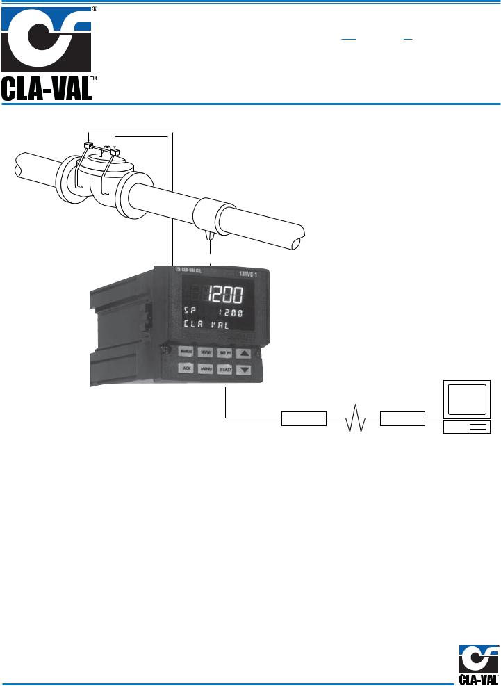
The Cla-Val 131VC-1 Electronic Control System is designed to achieve unprecedented valve control accuracy and stability. Ideal for remote valve control, the 131VC-1 Electronic Control System provides the interface between SCADA system computers and hydraulic control valves sites.
Optional Remote Control
Modem |
Modem |
Computer
Electronic Control of Hydraulic Valves
The 131VC-1 Electronic Control System is designed to work in conjunction with Cla-Val 131 Series hydraulic control valves— a combination that takes advantage of the simplicity of hydraulic valve operation and the control possibilities available with electronics.
The 131VC-1 Electronic Control System receives transmitted signals and activates dual solenoid pilots on the hydraulic control valve. These pilots direct hydraulic pressure within the system to position and regulate the valve. By continuously comparing system conditions to the programmed set-point, the system is automatically maintained at the desired value.
Additional important control features, unique to this type of valve control, are offered as standard. They are designed for user friendly operation and system safety and are addressed in this brochure.
Key Advantages
•Proven reliable hydraulic control valve
•Low electric power requirement
•Solid state electronic components
•No motors, bearings, bushings or packings to wear out or leak
We Not Only Sell Valves—
We Provide Solutions

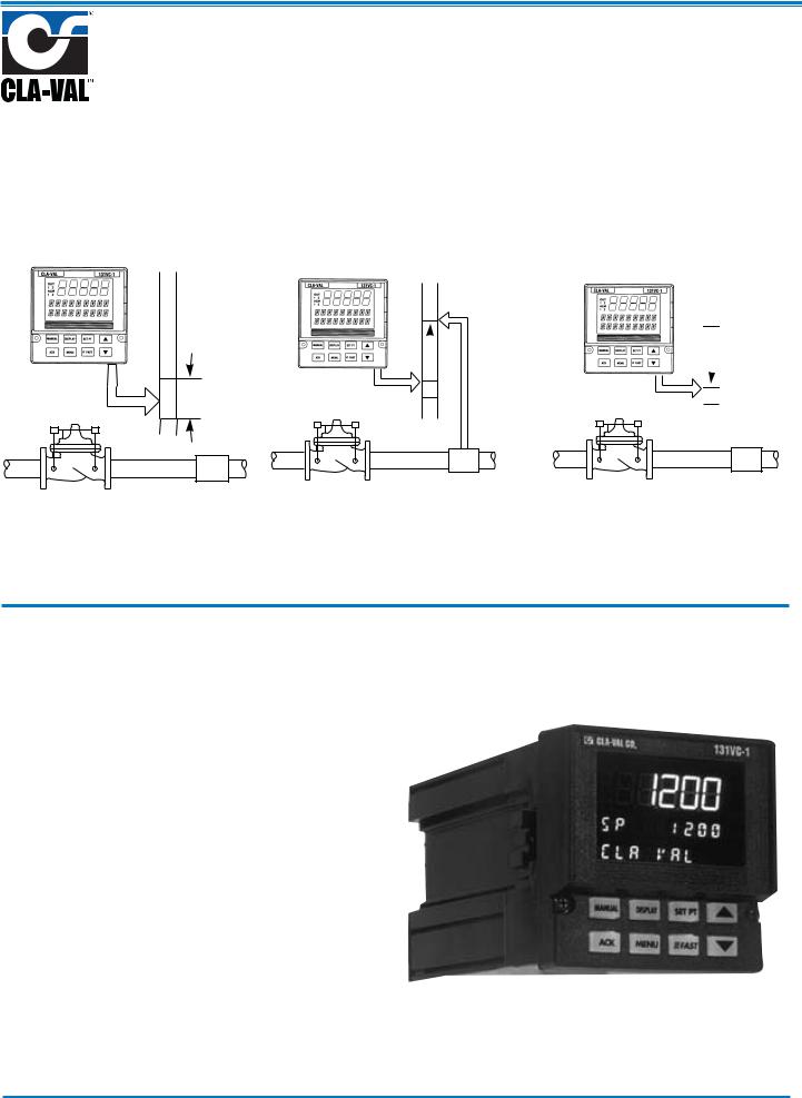
How it Works
1. Set-Point Command
Set-point command is received from a remote location or entered via the key pad into the Electronic Valve Controller.
2. Feedback and Comparison
The Electronic Valve Controller compares the feedback signal from the transmitter to the set-point. If the deviation exceeds the deadband, the valve control system is activated.
3. Valve Actuation
The Electronic Valve Controller actuates the solenoid controls, causing the valve to modulate as needed to regain the set-point condition.
Set-Point Command
Dead
Band
Deviation
Transmitter
Feedback
Signal
Devitation


Transmitte
Feedback
Signal
131-01 Valve |
Transmitter |
131-01 Valve |
Transmitter |
131-01 Valve |
Transmitter |
|
Keypad & Display
Display
The 131VC-1 has been engineered to be the industry’s most user friendly controller. With three digital displays areas (two offering up to 9 characters of true alphanumeric), the 131VC-1 effectively eliminates cryptic messages, sub-routines and loops that could confuse even the most experienced operator. The bright, crisp display is vacuum fluorescent, and offers much better readability than any other display technology. Additional operator-friendly features include: custom programmable alarm messages, illuminated keys, and an easy-to-use menu system.
Status Indicators - Four status indicators show the controller’s operating status at all times:
Manual Key Light: For manual control.
Set-point Key Light: For indication of remote control.
Output Indicator: “OUT” and indicator lights illuminate when either output 1 or 2 are on.
Alarm Indicator: “ALM” and indicator lights illuminate when either output 1 or 2 are on.
Keys Pads: All menu entry, configuration, tuning and set-point controls is entered through rugged backlit rubber keys. A simple menu system prompts the operator, step by step, through all procedures. Security system prevents unauthorized changes to all values.

Features
Alarm - Programmed to signal when system conditions exceed a desired value or in the event of a system component failure. It can be configured to be latching or non-latching, normally open or normally closed contact with deadbands.
Absolute Alarm - Activates when the process variable exceeds alarm set-point. It can be either high and/or low acting. Deviation Alarm - Shifts as the set-point is changed. It can be symmetrical or asymmetrical.
Fault Alarm - Activates when the process variable is lost.
Set-Point Rate of Change - Prevents accidental or sudden changes in the programmed set-point. It is also invaluable when used on high differential or surge sensitive applications where valve speed of operation must be tightly controlled.
Process Variable Backup - Can automatically recognize secondary process variable or can be programmed to open or close valve or can default to backup pilot system using alarm function.
DC Power Supply - Provides source of power for signal transmitter.
Retransmission - Transmit process variable or set-point values.
Offsets - Adjusts the process variable and remote set point settings if respective signals do not match.
Filter - Stabilizes process variable signal when required.
Security System - Prevents unauthorized changes.
Input Linearization - For flow measurement across orifices, venturies, etc.
Digital Inputs - Selects specific set-points. (optional)
NEMA 4X Enclosure (optional)
Input Signals
The 131VC-1 Electronic Control System is designed to accept industry standard 4-20 mA full scale signals for pressure, flow or level control from customer supplied transmitter(s).
Flow Measurement using a differential signal requires activating the square root extractor to obtain direct flow readout.
Modulating Level Control requires the use of an optional X117 Valve Position Transmitter in addition to a level transmitter.
Valve Position Control requires an optional X117 Valve Position Transmitter installed on the valve.
Other configurations are available on a special order basis, consult the factory for details.
Specifications
Control Input:
4-20 mA full scale (others optional)
Control Parameters
Proportional Bands: 1 to 999%, settable in 0.1% increments independently for opening and closing
Deadbands: achievable up to 15% of input range Cycle Time: 1 to 120 seconds in 1 sec. increments.
Environmental Parameters
Temperature: 0°C to 50°C (32°F to 1 22°F) Humidity: 10 to 90%, non-condensing
Power Consumption
15 watts Max. at 120 VA, 50160 Hz
Voltage and Frequency
Universal power supply: 90 to 250 VAC, 48 to 62 Hz. 24 to 30 volts AC or DC, +/- 5%.
Noise Immunity
Common mode rejection (process input): >120 db. Normal mode rejection (process input): >80 db. AC line is double filtered and transient protected. Snubbers are provided for each relay output.
Construction
Case: extruded, non-perforated black anodized aluminum with ABS plastic sleeve.
Bezel: Black plastic ABS. Chassis assembly: plug-in type.
Keys: Silicone rubber with diffusion printed graphics. NEMA rating: front panel conforms to NEMA 4X when instrument is properly installed.
Agency Approvals
LR 84603 |
U |
LISTED |
® L |
Process Control Equipment |
|
|
|
4N66 |
Memory Retention
Lithium battery maintains all programming for approximately ten years.
Security
There are two levels of access: restricted and full. A configurable code is used to enter the full access level. Functions not available in the restricted level are configurable.
 Loading...