

Page 1
BUILT IN ELECTRIC FIREPLACE
INSTALLATION GUIDE
MODEL NUMBERS:
33EB304GRS
39EB364GRS
45EB424GRS
CONSUMER SAFETY INFORMATION
PLEASE READ THIS MANUAL BEFORE INSTALLING THIS APPLIANCE
WARNING
IF THE INFORMATION IN THIS MANUAL IS NOT FOLLOWED,
AN ELECTRIC SHOCK OR FIRE MAY RESULT CAUSING
PROPERTY DAMAGE, PERSONAL INJURY OR LOSS OF LIFE.
DO NOT STORE OR USE GASOLINE OR OTHER FLAMMABLE
VAPORS AND LIQUIDS IN THE VICINITY OF THIS
OR ANY OTHER APPLIANCE.
Thank you and congratulations on your purchase of a Classic Flame fireplace.
Please read the installation instructions before installing and operating
this appliance.
IMPORTANT: Read all instructions and warnings carefully before starting installation.
Failure to follow these instructions may result in a possible electric shock, fire
hazard and/or injury and will void the warranty.
For Customer Service:
E-Mail: [email protected]
In English Call: 866-661-1218
En Français Call: 866-374-9203
En Español Call: 866-661-1218
E-1
Twin-Star International, Inc.
Delray Beach, FL 33483
Made in China
Printed in China
Page 2
LISTINGS AND CODE APPROVALS
THE BUILDERS BOX SERIES HAS BEEN TESTED AND APPROVED IN ACCORDANCE WITH THE
CSA, No.220391, STANDARDS FOR FIXED AND LOCATION
DEDICATED ELECTRIC ROOM HEATERS.
MODEL SPECIFICATIONS
MODEL
NUMBER DESCRIPTION VOLTAGE
33EB304GRS 33” STANDARD 120/208/240 1440/2100/2800 YES 12.00/10.10/11.67
39EB364GRS 39” STANDARD 120/208/240 1440/2100/2800 YES 12.00/10.10/11.67
45EB424GRS 45” STANDARD 120/208/240 1440/2100/2800 YES 12.00/10.10/11.67
RATED POWER
WATTS
REMOTE
CONTROL AMPS
!!! WARNING !!!
THE INSTALLATION OF THE FIREPLACE UNIT MUST COMPLY WITH THE APPLICABLE
LOCAL AND/ OR NATIONAL ELECTRICAL CODES AND UTILITY REQUIREMENTS.
THIS INSTALLATION SHOULD BE ENTRUSTED TO DULY QUALIFIED
PERSONNEL WHERE REQUIRED BY LAW.
STEP - BY - STEP INSTALLATION OVERVIEW
(please read all instructions before installation)
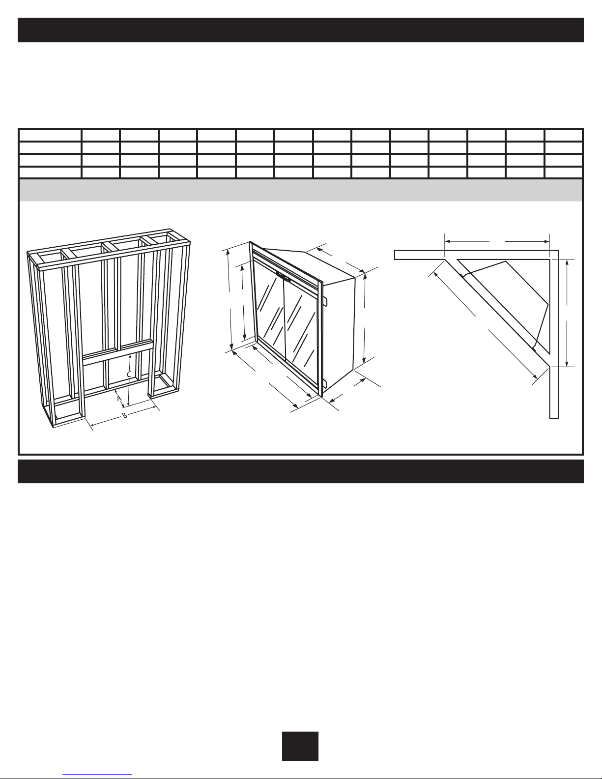
1) Rough in framing following the
recommended dimensions. (see figure 1)
2) Allow at least 8” of service cable for
connecting power supply wire to junction
box on fireplace insert when installing
before finishing wall. Allow up to 4 feet of
service cable for connecting power supply
wire to junction box on fireplace insert
after finishing wall.
3) Remove the outer jacket and strip the
individual conductors ½” from end.
4) Loosen the screw securing the junction
box cover and remove the cover.
5) Place unit in position in the framed
opening, level with shims if necessary
and attach unit to frame using mounting
flanges provided ( see Section 3).
6) Wire a dedicated, properly fused circuit with
a 15 amp rating for the appropriate voltage
(120, 208/240). (See table above)
7) Install wall thermostat as outlined on
page 10 section E
8) Place all connections inside the junction
box. Secure the junction box cover on the
unit.
When installing a cable clamp make sure it
grips only the jacket of the service cable
and thermostat wire.
!POWER SELECTION WARNING!
This unit is factory wired for 240 volt power supply.
If 120 volt operation is required, slide the voltage switch
! !
and reconfigure the wiring accordingly (see figure 2).
Wires L1, L2, N & G are attached to the rear of
the junction box for easy access.
E-2
Page 3
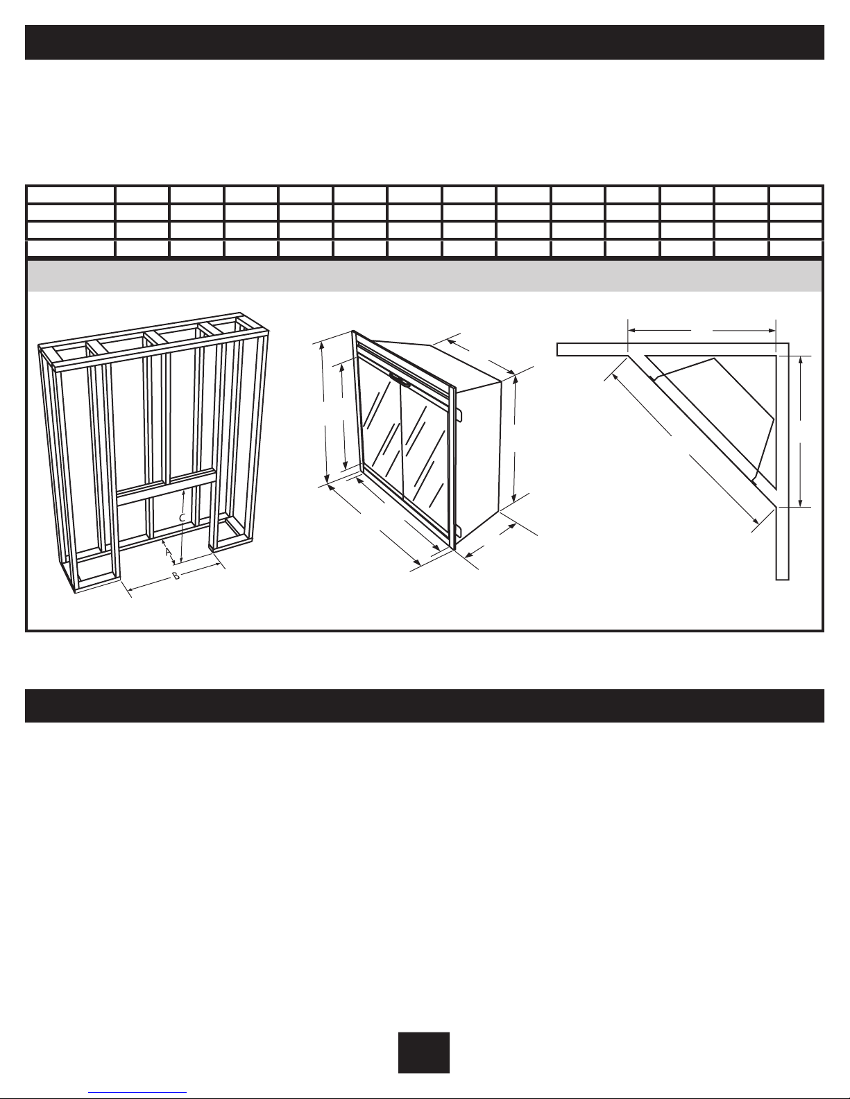
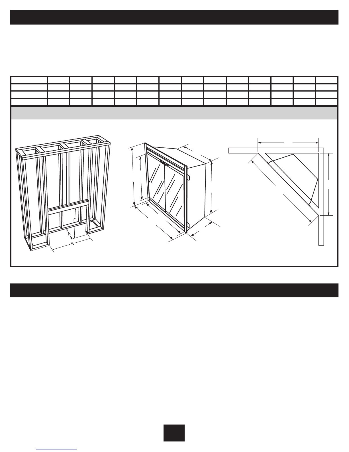
Section 1: Framing
This fireplace is a zero clearance design. No
combustibles can be placed on the top
surface of the fireplace. Combustibles may
be installed to the edge of the unit.
MODEL A B C D E F G H I J K L M
33EB304GRS 15.0” 33.0” 29” 28.5”
39EB364GRS 16.0” 39.0” 33” 32.7” 27.2” 38.7” 36.0” 22.0” 27.6” 15.3” 55.0” 38
45EB424GRS 16.0” 45.0” 33” 32.7” 27.2” 44.7” 41.9” 28.1” 28.0” 15.3” 61.0” 43.1
23.0” 32.8” 29.6” 18.25” 23.6” 14.3” 49.0” 34.7” 34.7
Four mounting flanges on the sides of the unit
are provided to facilitate installation.
Insulation and vapor barrier should be placed
a minimum of 2 inches from the unit.
.9”
”
Framing Specifications: Figure 1
L
H
E
D
I
K
38.9””
43.1
”
M
G
F
Section 2: Recommended Power Supply Wire Specifications
For 120 volt installations use two conductor,
non-metallic sheath cable with ground wire
(3 wires total) for the incoming power supply
on fireplace inserts. Use the appropriate wire
to meet local and national electrical codes for
rated power consumption.
For 208/240 volt installations use three
conductor, non-metallic sheath cable with
ground wire (4 wires total) for the incoming
power supply on fireplace inserts. Use the
appropriate wire to meet local and national
electrical codes for rated power consumption.
J
Two conductor, non-metallic sheath cable with
ground wire (3 wires total) is recommended
for installation of a wall mounted thermostat
for use on fireplace inserts.
Recommended Wire and
Fusing Requirements
Use appropriate wire to meet local and
national electrical codes for rated power consumption. All wire gauges should be
12 gauge with a dedicated 15 amp breaker.
E-3
Page 4
115
230
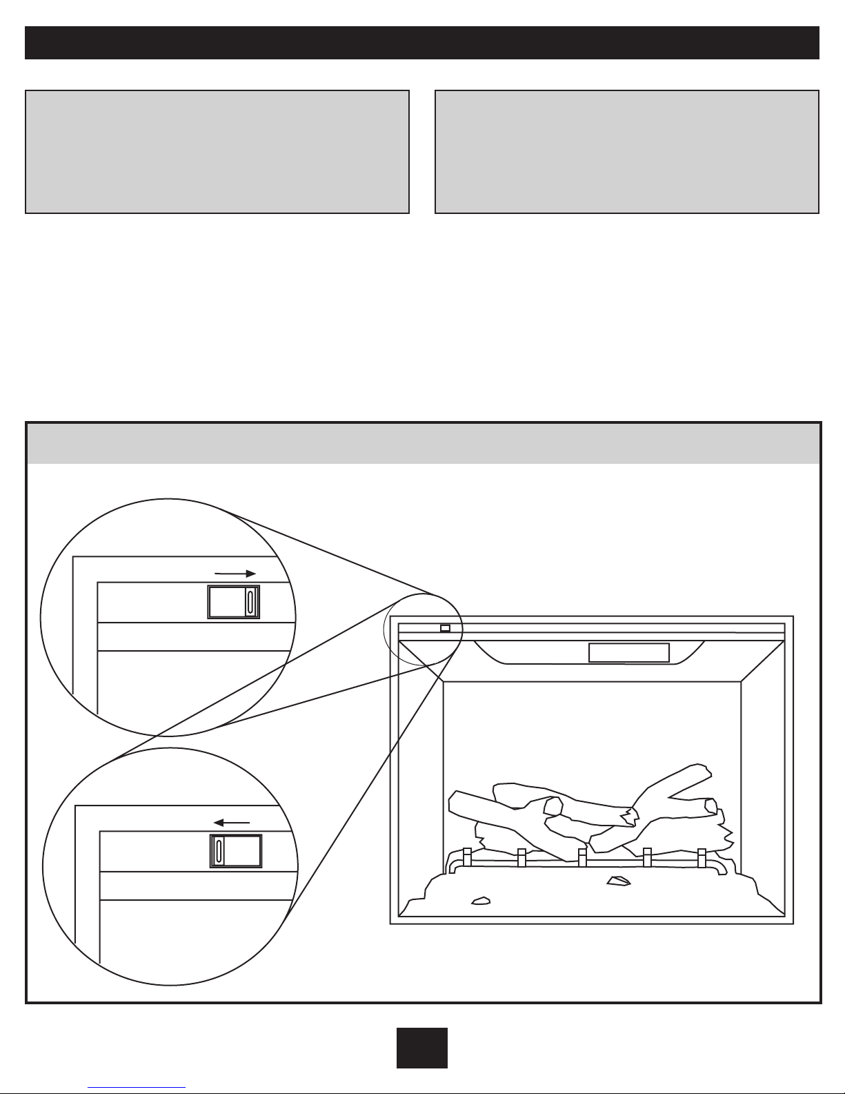
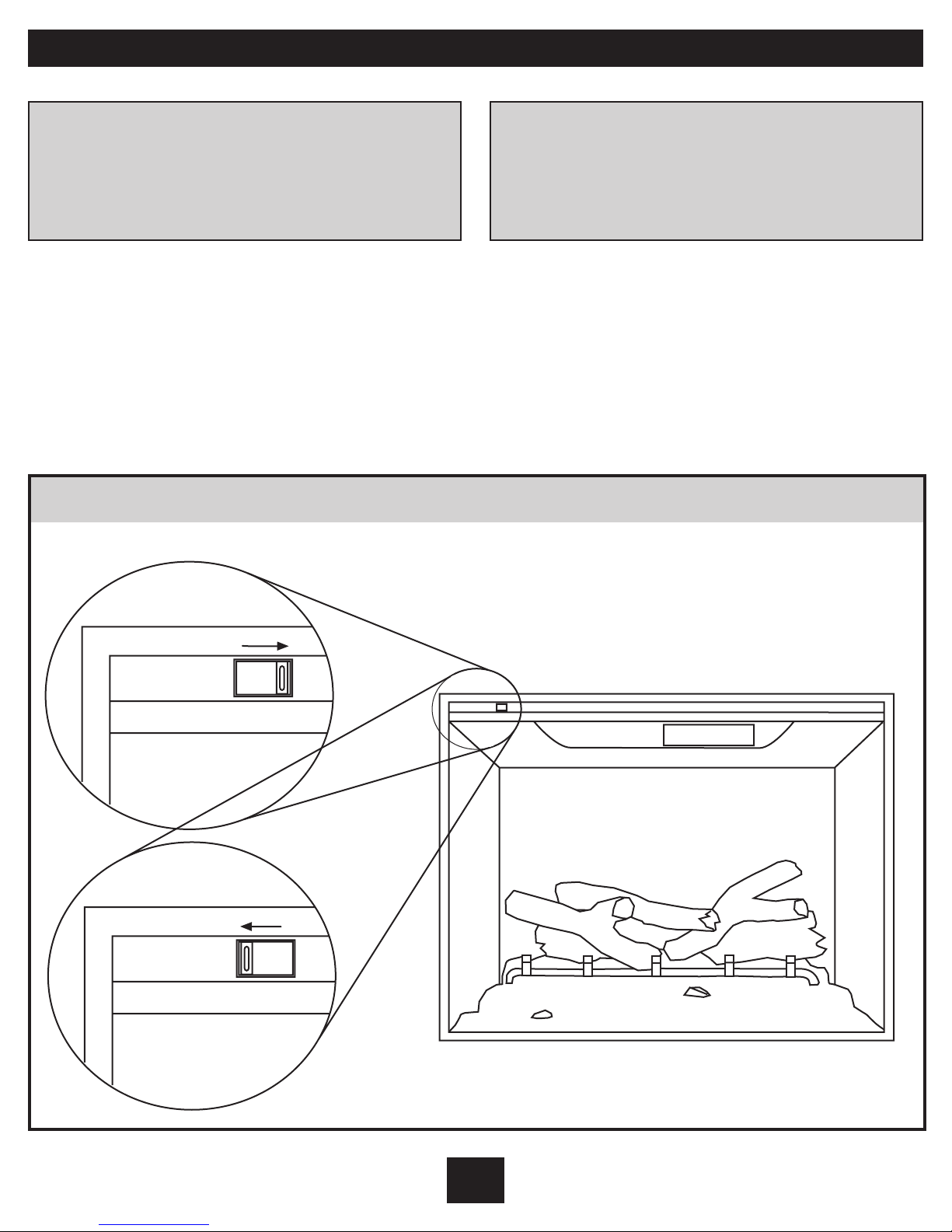
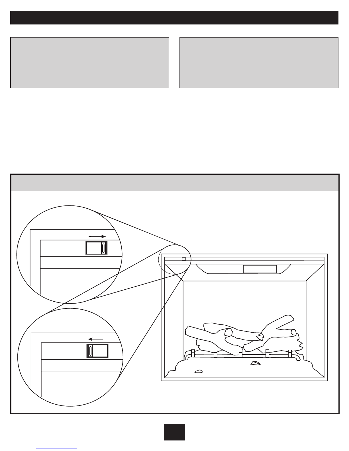
Section 3: Voltage Selector Switch Location
Important:
Ensure that the incoming power supply
voltage matches the setting of the
voltage selector switch!!!!!!
The voltage selector switch is located inside
the exhaust panel on the top left hand
corner. Carefully insert a flat headed screwdriver inside the exhaust panel through the
hole in the mesh to change the switch from
240 volts (230 position) to 120 volts (115
position). The unit ships with the switch in the
230V position.
Voltage Selector Switch: Figure 2
Caution:
When changing the voltage selector switch
from 240 volts to 120 volts ensure that the
power supply is turned off.
When wiring the unit for 208/240 volts the
voltage selector switch should be in the 230
volt position. (see figure 2)
When wiring the unit for 120 volts the voltage
selector switch should be in the 115 volt
position. (see figure 2)
E-4
Page 5
STUD
WOOD OR METAL
MOUNTING FLANGE
RD WY LLA EEHS / CORT K
MAREC
I
C
ELIT
DRYWALL / SHEETROCK
CERAMIC TILE
STUD
9/16”
3/8”
MOUNTING FLANGE
INSERT
TOP
VIEW
FRONT
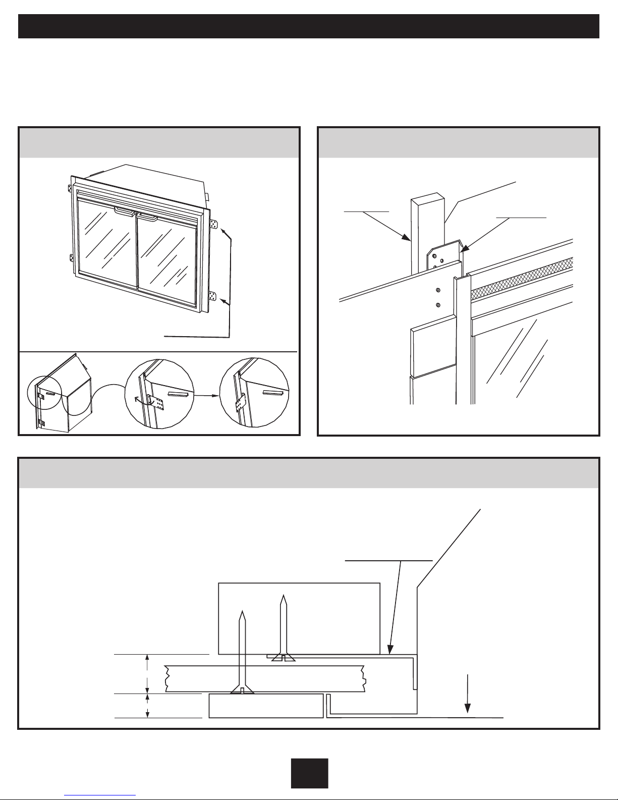
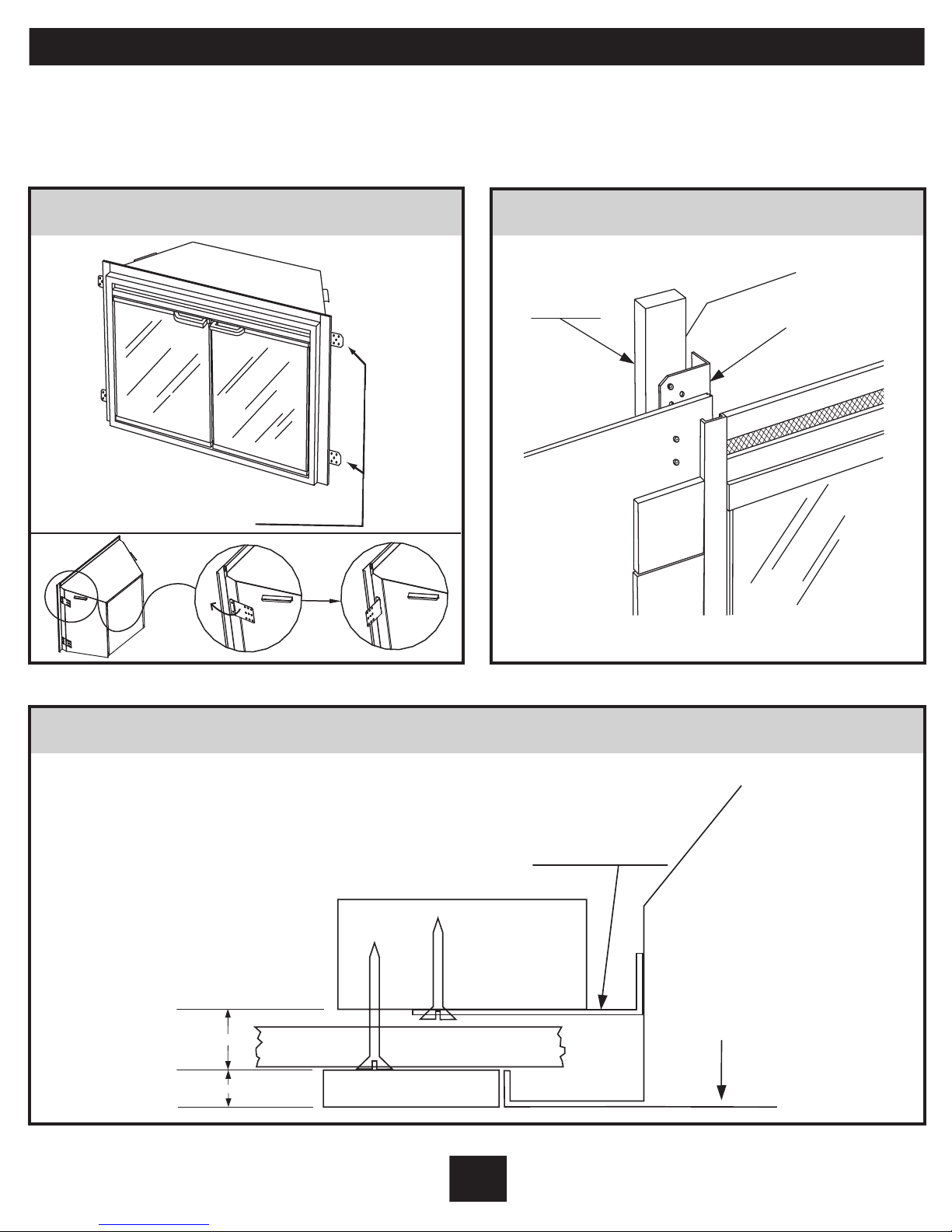
Section 4: Mounting Flanges
There are two mounting flanges located on each side of the fireplace insert. In order to facilitate
the transportation, we make the mounting flanges into flat status.
Please bend the mounting flanges into 90
(please see the figure 3)
o
using suitable hardware before installation.
Mounting Flange Location: Figure 3
NITNUOM G
EGNALF S
o
90
Bend 90o
to outside
Picture after
bending 90
Wall and Mounting Flange: Figure 4
o
Mounting Tolerances - Top View: Figure 5
E-5
Page 6
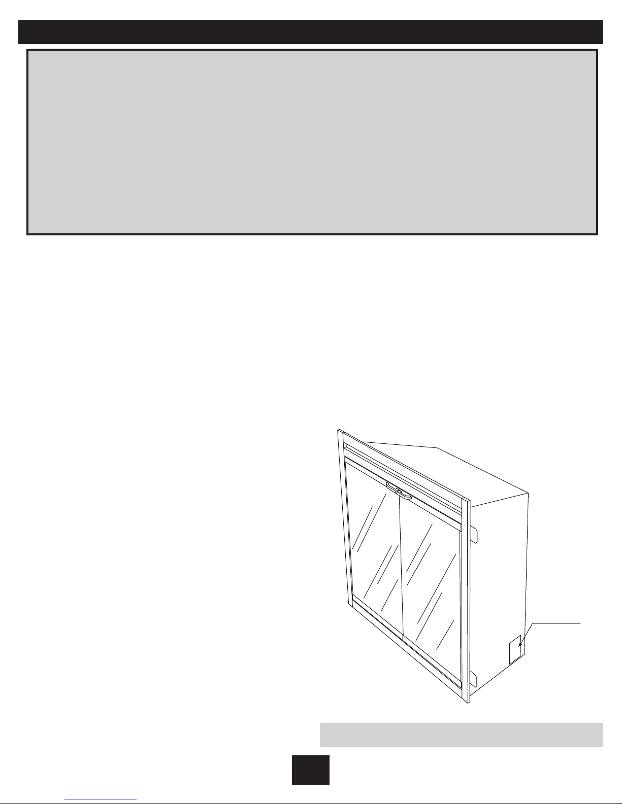
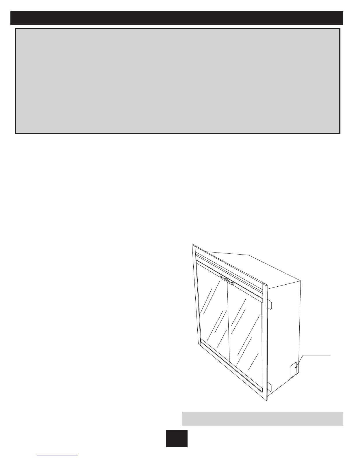
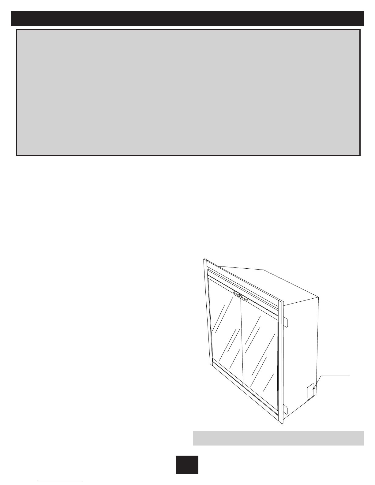
JUNCTION BOX
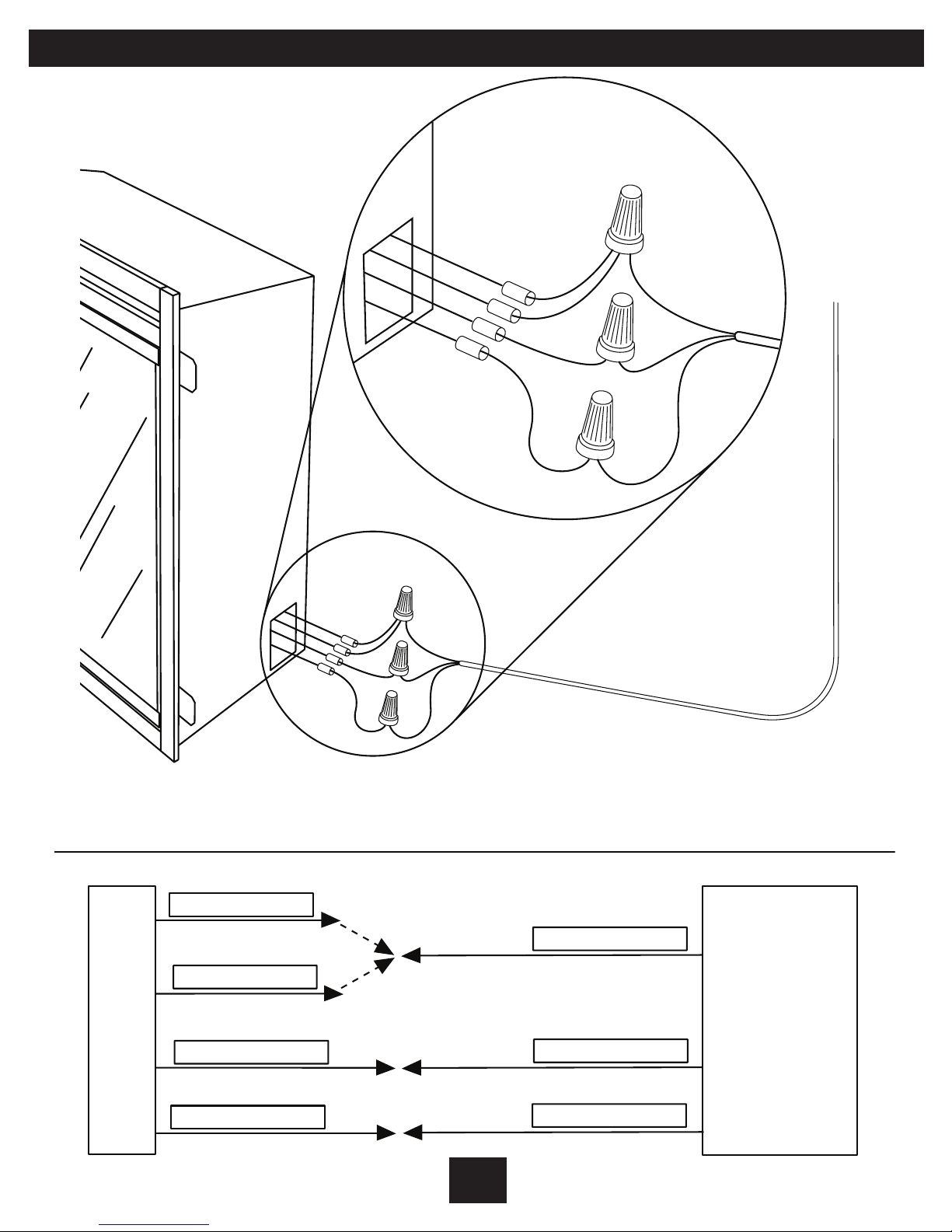
Section 5: 120 Volt Installation Instructions
Important
• The unit is factory configured for 240 volt
operation.
• Use 2 conductor wire with ground (3 wires
total) from the power supply (breaker
panel) to the junction box on the unit.
1. Locate the voltage selector switch inside
the exhaust panel on the top left hand
corner of the unit. (see figure 2 on page 3)
2. Confirm the switch is set to 120 volt
configuration ( 115 volt is printed on
switch).
3. Loosen the screw securing the junction
box cover and remove the cover.
4. Remove the knockouts (if necessary)
or use a cable clamp (not provided).
5. Pull out the four wires marked L1, L2,
N, and G.
6. Connect the black L1 wire from the unit to
the black L1 from the power supply.
7. Connect the red L2 wire and the N wire
from the unit to the N wire from the
power supply.
8. Connect the green ground wire from the
unit to the ground from the power supply.
9. Ensure that all connections are tight.
10. Insert all the wiring back into the unit and
secure with a cable clamp.
• All wiring must be completed prior to
installing the unit.
• Ensure that the voltage selector switch is
in the proper position for the required
supply voltage prior to connecting the unit
to the power supply.
Junction Box Locator: Figure 6
E-6
Page 7
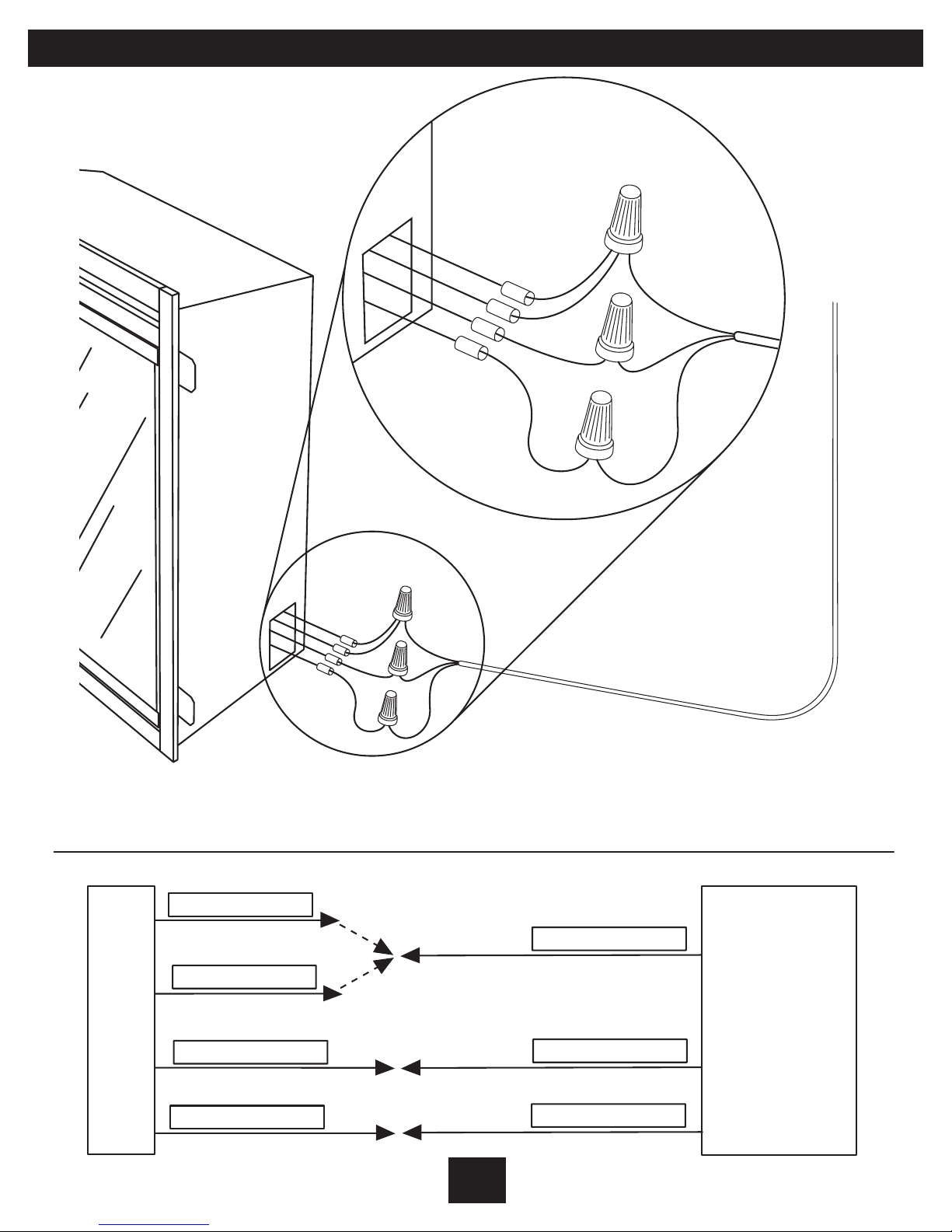
N - WHITE WIRE
L2 - RED WIRE
L1- BLACK WIRE
G- GREEN WIRE
N- WHITE WIRE
L1 - BLACK WIRE
G - GREEN WIRE
FIREPLACE -JUNCTION BOX
120 VOLT
POWER SUPPLY
BREAKER
PANEL
N
L2
L1
G
N
L2
L1
G
Wire Connection Diagram: Figure 7
E-7
Page 8
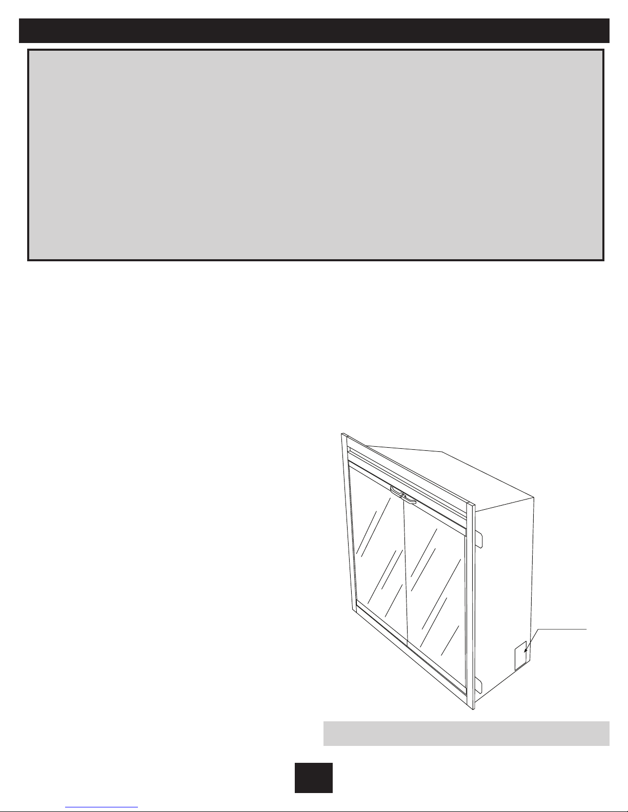
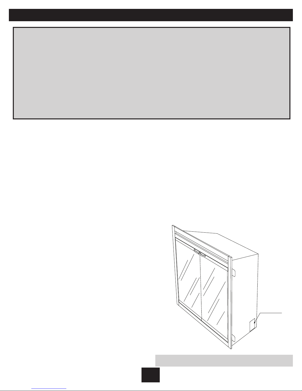
JUNCTION BOX
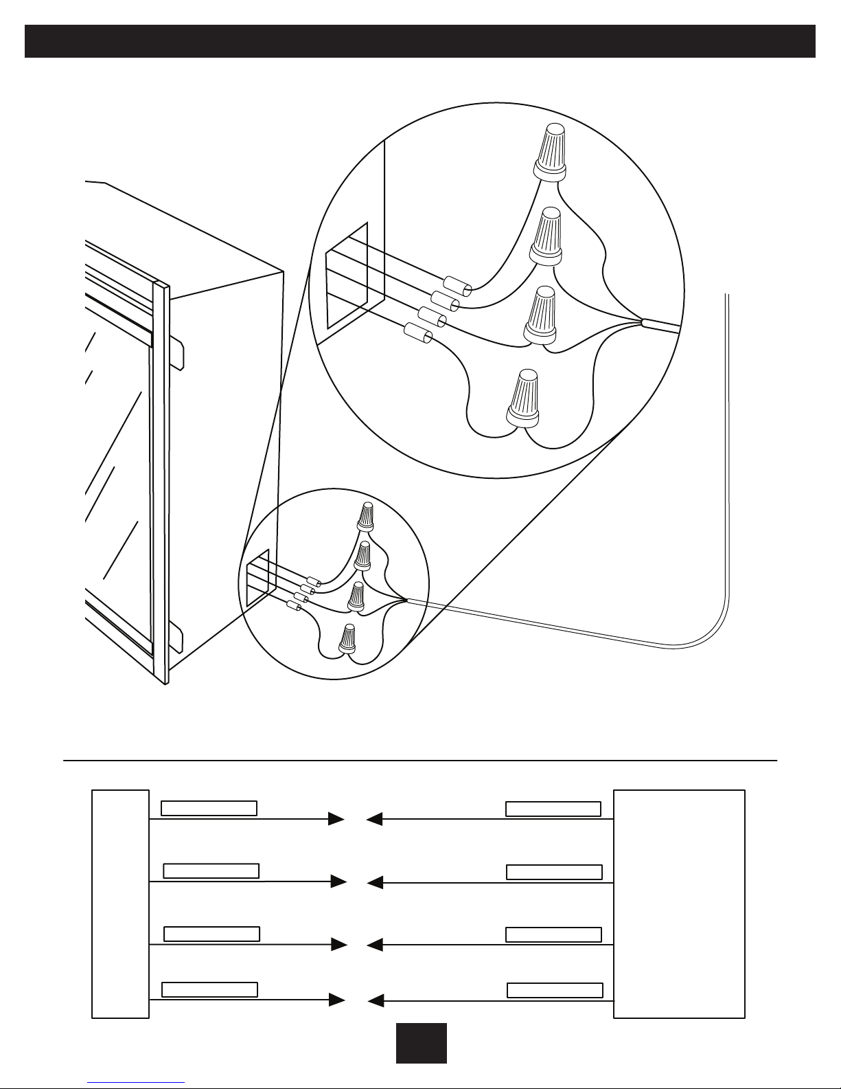
Section 6: 240 Volt Installation Instructions
Important
• The unit is factory configured for 240 volt
operation. You must set the voltage
selection switch to 240 volts (230 volt is
printed on the switch.
• Use 3 conductor wire with ground (4 wires
total) from the power supply (breaker
panel) to the junction box on the unit.
1. Locate the voltage selector switch inside
the exhaust panel on the top left hand
corner of the unit. (see figure 2 on page 3)
2. Confirm the switch is set to 240 volt
configuration (230 volt is printed
on switch).
• All wiring must be completed prior to
installing the unit.
• Ensure that the voltage selector switch is
in the proper position for the required
supply voltage prior to connecting the unit
to the power supply.
3. Loosen the screw securing the junction
box cover and remove the cover.
4. Remove the knockouts (if necessary) or
use a cable clamp (not provided).
5. Pull out the four wires marked L1, L2,
N, and G.
6. Connect the black L1 wire from the unit to
the black L1 from the power supply.
7. Connect the red L2 wire from the unit to
the red L2 from the power supply.
8. Connect the white N wire from the unit to
the white N wire from the power supply.
9. Connect the green ground wire from the
unit to the ground from the power supply.
10. Ensure that all connections are tight.
11. Insert all the wiring back into the unit and
secure with a cable clamp.
Junction Box Locator: Figure 8
E-8
Page 9
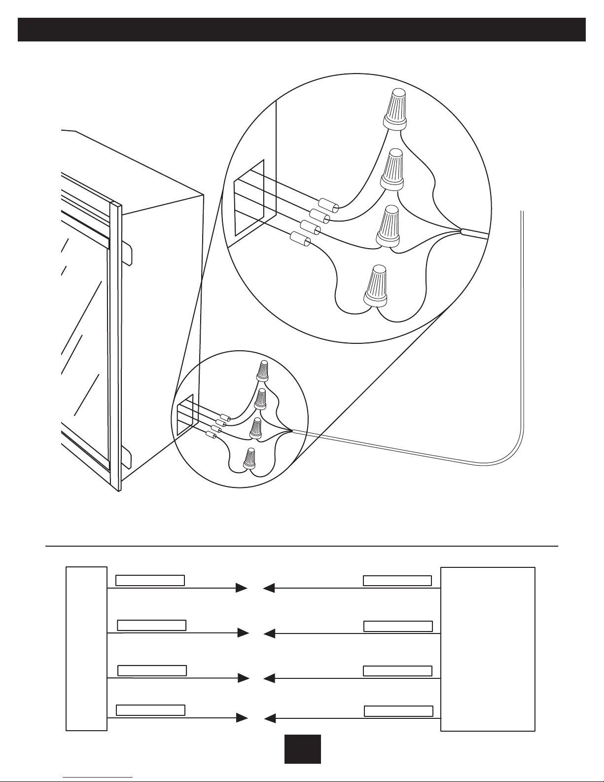
N - WHITE WIRE
L2 - RED WIRE
L1- BLACK WIRE
G- GREEN WIRE
N- WHITE WIRE
L1 - BLACK WIRE
G - GREEN WIRE
FIREPLACE -JUNCTION BOX
240 VOLT
POWER SUPPLY
BREAKER
PANEL
L2 - RED WIRE
N
L2
L1
G
N
L2
L1
G
Wire Connection Diagram: Figure 9
E-9
Page 10
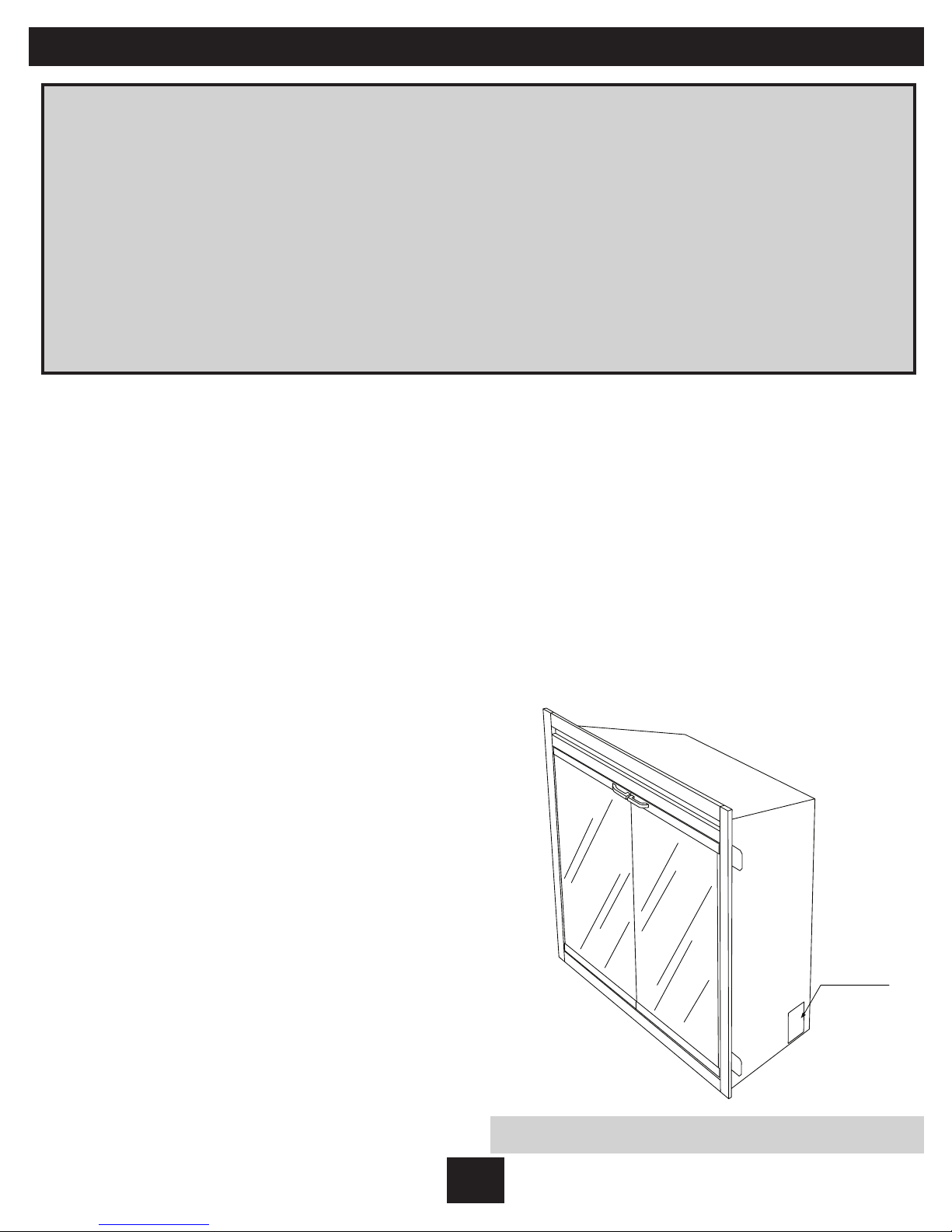
JUNCTION BOX
Section 7: Wall Mounted Thermostat Wiring For 120/240 Volt
ATTENTION
• Install main power connection with
appropriate voltage as per Section C
or Section D.
• Install a 2 conductor wire with ground
(3 wires total) from the thermostat w
all
box to the junction box on the unit.
1. Loosen the screw securing the junction
box and remove the cover.
2. Remove the knockouts (if necessary) or
use the provided cable clamp.
3. Pull out the three wires marked T1, T2,
and TG. (red, red, and green)
4. Remove the wire connector and separate
the wires marked T1 & T2.
5. Connect the (red) T1 wire from the unit
to the white (neutral) wire from the wall
thermostat box by using a wire connector.
(not supplied)
• Wiring of the thermostat must be
completed prior to the mounting of
the unit.
• The f
ollowing installation instructions are
for a single pole thermostat.
10. Connect the other end of the green
(ground) wire from the thermostat wall
box to the back plate of the wall mounted
thermostat with a ground screw.
11. Ensure that all connections are tight.
12. Insert all the wiring of the wall mount
ed
thermostat into the wall box.
13. Insert all the wiring back into the unit and
secure with a cable clamp.
6. Connect the other end of the white
(neutral) wire from the thermostat wall
box to the red wire from the wall
thermostat.
7. Connect the (red) T2 wire from the unit to
the black wire from the thermostat wall
box by using a wire connector.
(not supplied)
8. Connect the other end of the black wire
from the thermostat wall box to the black
wire from the wall thermostat.
9. Connect the green (ground) TG wire from
the unit to the green (ground) wire from
the thermostat wall box by using a wire
connector. (not supplied)
Junction Box Locator: Figure 10
E-10
Page 11
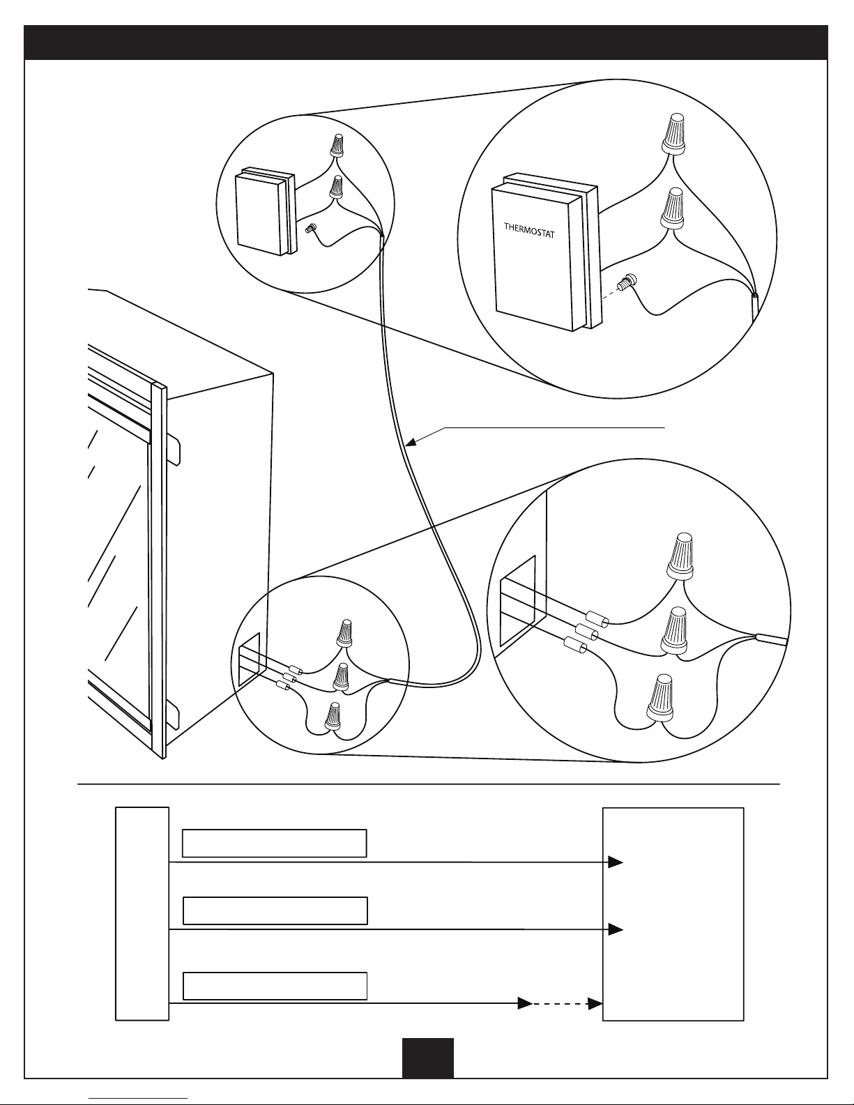
T 2 - RED WIRE
FIREPLACE -JUNCTION BOX
MECHANICAL
LINE VOLTAGE
THERMOSTAT
WALL MOUNTED
T 1 - RED WIRE
T G - GREEN WIRE
T 2
T 1
T G
2 CON DUC TOR WIRE FR OM WAL L T HER MOS TAT
T 2
T 1
T G
B
L
A
C
K
W
I
R
E
W
H
I
T
E
W
I
R
E
G
R
O
U
N
D
W
I
R
E
R
E
D
W
I
R
E
B
L
A
C
K
W
I
R
E
Wire Connection Diagram: Figure 11
E-11
Page 12
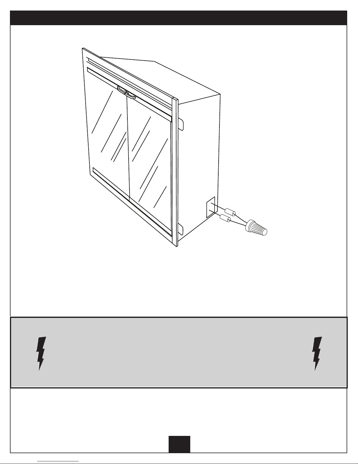
T 2
T 1
Wire Connection Diagram: Figure 12
If the external thermostat won't be used, then wire T1 and wire T2 should be
bound together using a wire nut.
When the wiring is complete, a thorough “testing cycle” must
be performed to check the operation of the unit PRIOR to the
! !
wall / area being closed up, tiled, and/or bricked.
E-12
Page 13
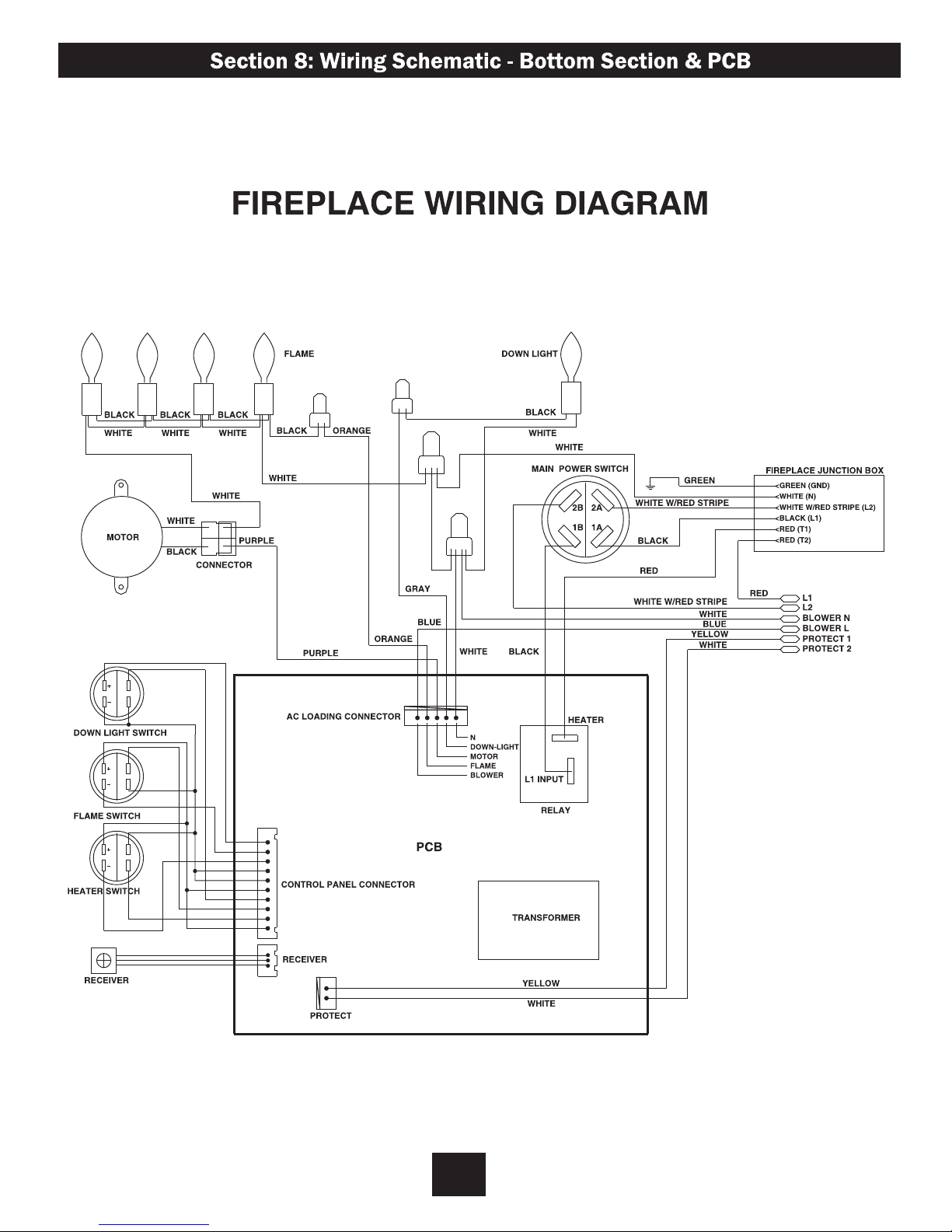
E-13
Page 14
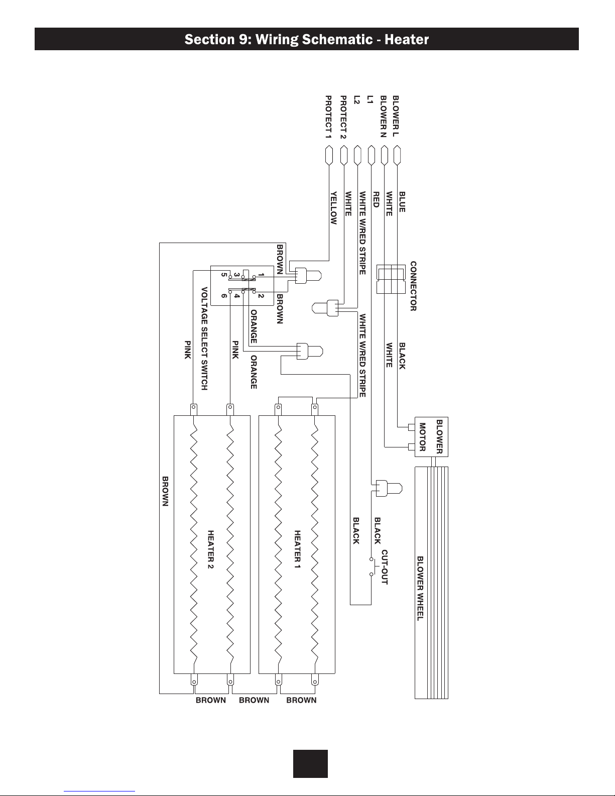
E-14
Page 15

115 S.E. 4th Avenue • Delray Beach, Florida 33483
A Division of Twin-Star International, Inc.
Phone: 561-330-3201 • Fax: 561-330-3205
www.classicflame.com
E-15
Page 16
FOYER ÉLECTRIQUE ENCAS
GUIDE D’INSTALLATION
NUMÉRO DE MODÈLES :
33EB304GRS
39EB364GRS
45EB424GRS
RENSEIGNEMENTS SUR LA SÉCURITÉ
VEUILLEZ LIRE CE GUIDE AVANT D’INSTALLER L’APPAREIL
AVERTISSEMENT
TRÉ
NE PAS SUIVRE LES RENSEIGNEMENTS INDIQUÉS DANS CE GUIDE POURRAIT
ENTRAÎNER UN CHOC ÉLECTRIQUE, UN INCENDIE, DES BLESSURES OU LE DÉCÈS.
NE PAS CONSERVER OU UTILISER D’ESSENCE OU TOUT AUTRE LIQUIDE OU
SOURCE DE VAPEURS INFLAMMABLES PRÈS DE CET APPAREIL OU DE TOUT
AUTRE APPAREIL DU MÊME TYPE.
Nous vous remercions et vous félicitons d’avoir acheté un foyer Classic Flame.
Veuillez lire les instructions d’installation avant d’installer et de faire fonctionner
cet appareil.
IMPORTANT: V
avant de commencer l’installation de l’appareil. Ne pas se confor
instructions pourrait entraîner un choc électrique, un risque d’incendie et/ou de blessure,
en plus d’annuler la garantie.
euillez lire attentivement toutes les instructions et tous les avertissements
mer à ces
Pour le service à la clientèle :
Courriel: [email protected]
en anglais, composez le : 866-661-1218
en fr
ançais, composez le : 866-374-9203
spagnol, composez le : 866-661-1218
en e
F-1
Twin-Star International, Inc.
Delray Beach, FL 33483
Fabriqué en Chine
Imprimé en Chine
Page 17
LISTES ET HOMOLOGATIONS
LA SÉRIE BUILDERS BOX A ÉTÉ TESTÉE ET APPROUVÉE CONFORMÉMENT AUX NORMES 220391
DE LA CSA POUR LES APPAREILS DE CHAUFFAGE AUTONOMES FIXES INTÉRIEURS.
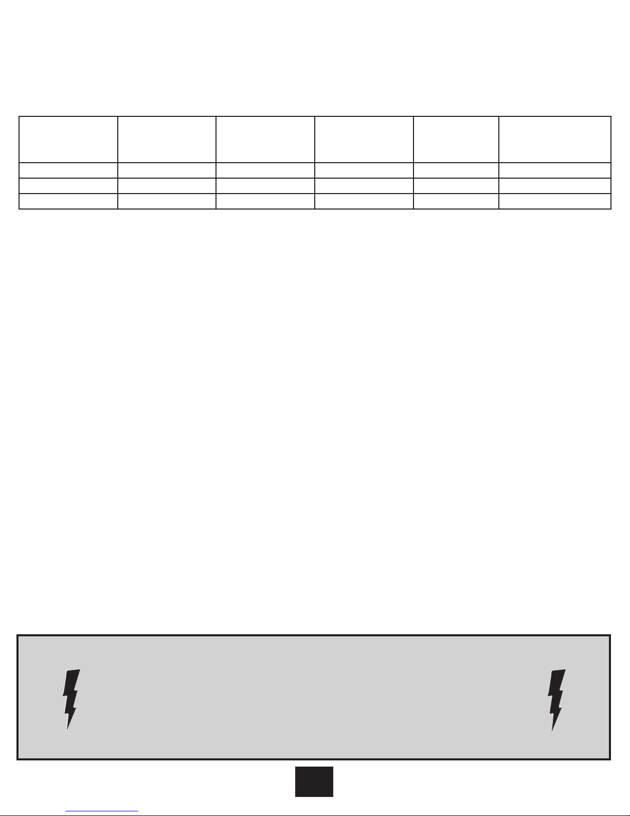
SPÉCIFICATIONS DES MODÈLES
NUMÉRO DU
MODÈLE DESCRIPTION TENSION
33EB304GRS
39EB364GRS STANDARD, 39 po
45EB424GRS
STANDARD, 33 po 120/208/240 1440/2100/2800 OUI 12.00/10.10/11.67
120/208/240
STANDARD, 45 po
120/208/240
PUISSANCE
NOMINALE EN
WATTS
1440/2100/2800
1440/2100/2800
TÉLÉCOM-
MANDE AMPÈRES
OUI
OUI
12.00/10.10/11.67
12.00/10.10/11.67
!!! AVERTISSEMENT !!!
L’INSTALLATION DE CE FOYER DOIT ÊTRE CONFORME AUX CODES DE L’ÉLECTRICITÉ LOCAUX
OU NATIONAUX. CETTE INSTALLATION DEVRAIT ÊTRE CONFIÉE À UNE PERSONNE DÛMENT
QUALIFIÉE, LORSQUE LA LOI L’EXIGE.
INSTALLATION ÉTAPE PAR ÉTAPE
(veuillez lire toutes les instructions avant l’installation)
1) Tracer une ébauche du cadre du foyer en
suivant les dimensions recommandées (voir
la figure 1).
2)Lorsque vous procédez à l’installation sur un
mur non fini, laissez une longueur de câble
d’au moins 20 cm (8 po) pour raccorder
le cordon d’alimentation à la boîte de connexion du foyer encastrable. Cependant,
si vous installez le foyer sur un mur déjà
fini, assurez-vous de laisser au moins 1,22
m (4 pi) de câble pour raccorder le cordon
d’alimentation à la boîte de connexion du
foyer encastrable.
3) Retirez la gaine extérieure et coupez une
bande de 1,27 cm (1/2 po), à l’extrémité de
chacun des conducteurs.
4) Desserrez la vis qui retient le couvercle de
la boîte de connexion et retirez le couvercle.
5) Mettez le foyer en place, dans l’ouverture.
Au besoin, nivelez-le ensuite avec des cales
puis fixez-le au cadre à l’aide des brides de
fixation fournies (voir la section 3).
6) Utilisez un fil provenant d’un circuit par-
ticulier convenablement protégé par des
fusibles, un fil ayant une valeur nominale de
15 ampères, pour obtenir la tension appropriée (120, 208/240) (voir le tableau ci-des-
sus)
7) Installez le thermostat mural comme indi-
qué à la section E de la page 10.
8) Mettez tous les fils à l’intérieur de la boîte
de connexion. Fixez ensuite le couvercle sur
la boîte. Lorsque vous installez un collier de
serrage, assurez-vous qu’il ne retient que la
gaine du câble de branchement et du fil du
thermostat.
!AVERTISSEMENT - CHOIX DE L’ALIMENTATION!
Ce foyer a été câblé en usine pour être utilisé avec une
alimentation 240 volts. Si ce foyer doit être utilisé avec une
! !
alimentation 120 volts, glissez le commutateur de tension
et reconfigurez le câblage de façon appropriée (voir la figure 2).
Pour faciliter l’accès aux fils, les fils L1, L2, N & G sont attachés
à l’arrière de la boîte de connexion.
F-2
Page 18
D
E
F
G
H
I
J
L
K
M
Section 1: Cadre
Ce modèle de foyer n’est pas soumis aux
normes de dégagement. Ne placez aucun
produit combustible sur la surface de celui-ci.
Vous pouvez cependant placer des produits
combustibles sur la bordure du foyer. Pour
MODÈLE A B C D E F G H I J K L M
33EB304GRS 15.0” 33.0” 29” 28.5” 23.0” 32.8” 29.6” 18.25” 23.6” 14.3” 49.0” 34.7” 34.7”
39EB364GRS
45EB424GRS
16.0”
16.0”
39.0”
45.0”
33”
33”
32.7”
32.7”
27.2”
27.2”
38.7”
44.7”
faciliter l’installation du foyer, quatre brides de
fixation sont installées sur les côtés du foyer.
L’isolant et le pare-vapeur devraient se trouver
à une distance minimale de 5 cm (2 po) du
foyer.
36.0”
41.9”
22.0”
28.1”
27.6”
28.0”
15.3”
15.3”
55.0”
61.0”
38.9”
43.1”
38.9”
43.1”
Spécifications pour le cadre : figure 1
Section 2 : Spécifications concernant les câbles d’alimentation recommandés
Pour une installation sur un circuit de 120
volts, utilisez un câble à gaine métalloïdique
avec deux conducteurs et un fil de mise à la
terre (3 fils au total) pour l’alimentation électrique entrante des foyers encastrables. Utilisez le fil approprié pour la puissance normale
requise selon les codes de l’électricité locaux
et nationaux.
Pour une installation sur un circuit de
208/240 volts, utilisez un câble à gaine
métalloïdique avec trois conducteurs et un
fil de mise à la terre (4 fils au total) pour
l’alimentation électrique entrante des foyers
encastrables. Utilisez le fil approprié pour la
puissance normale requise selon les codes de
l’électricité locaux et nationaux. L’on
recommande d’utiliser un câble à gaine
métalloïdique avec deux conducteurs et un fil
de mise à la terre (3 fils au total) pour installer
le thermostat mural pour foyer encastrable.
Exigences relatives aux fils et aux fusibles
recommandés
Utilisez le fil approprié pour la puissance normale requise selon les codes de l’électricité
locaux et nationaux. Tous les fil
un calibre de 1
2 et être relié à un disjoncteur
s doivent avoir
de 15 ampères dédié au foyer.
F-3
Page 19
115
230
Section 3: Emplacement du commutateur de tension
Important:
Assurez-vous que la tension d’alimentation entrante correspond au réglage du
commutateur de tension!!!!!!
Le commutateur de tension se trouve à l’intérieur
du panneau d’échappement, dans le coin supérieur gauche. Soyez prudent au moment d’insérer
un tournevis à lame plate à l’intérieur du panneau
d’échappement, à travers le trou dans la maille,
pour faire glisser le commutateur de 240 (position 230) à 120 volts (position 115). Lorsque le
foyer sort de l’usine, le commutateur est en position 230 volts.
Commutateur de tension : figure 2
Mise en garde :
Lorsque vous glissez le commutateur de
tension de 240 à 120 volts, assurez-vous
d’avoir coupé l’alimentation.
Lorsque vous installez les fils du foyer pour une
tension de 208/240 volts, placez le commutateur
de tension en position 230 volts (voir la figure 2).
Lorsque vous installez les fils du foyer pour une
tension de 120 volts, placez le commutateur de
tension en position 115 volts (voir la figure 2).
F-4
Page 20
SEDIRB
AXIF ED NOIT
GOUJON
BOIS OU MÉTAL
BRIDE DE FIXATION
CORTEEHS/ESPYG K
RRAC UAE
ED MARÉC QI UE
GYPSE/SHEETROCK
CARREAU DE CÉRAMIQUE
GOUJON
9/16”
3/8”
BRIDE DE FIXATION
VUE DU
DESSUS DE
L’INSERTION
AVANT
Section 4: Brides de fixation
Le foyer comporte une bride de fixation de chaque côté. Pour faciliter le transport, nous
aplanissons ces brides. Veuillez plier les brides de fixation à angle de 90º avec de la
quincaillerie appropriée avant d’installer le foyer. (Veuillez consulter la figure 3)
Emplacement des brides de fixation : figure 3
90
o
Pliez à 90º
vers l’extérieur
Image, une fois
la bride pliée à 90º
Brides de fixation et brides murales : figure 4
Tolérances requises pour l’installation – vue du dessus : figure 5
F-5
Page 21
BOÎTE DE JONCTION
Section 5: Instructions pour installation sur circuit 120 volts
Important
• Ce foyer a été réglé en usine pour fonctionner sous une tension de 240 volts.
• Utilisez 2 fils conducteurs avec un fil
de mise à la terre (3 fils au total) entre
l’alimentation électrique (panneau de
disjoncteurs) et la boîte de connexion se
trouvant sur le foyer.
1. Commencez par trouver le commuta teur de tension à l’intérieur du panneau
d’échappement, dans le coin supérieur
gauche du foyer (voir la figure 2 à la
page 3).
2. Assurez-vous que le commutateur soit
econfiguration 120 volts (115 volts est
indiqué sur le commutateur).
3. Desserrez la vis qui retient le couvercle de
la boîte de connexion et retirez le
couvercle.
4. Enlevez les alvéoles défonçables
(au besoin) ou utilisez un collier de
serrage (non fourni).
5. Sortez les quatre fils marqués L1, L2, N,
et G.
6. Raccordez le fil noir L1 du foyer au fil noir
L1 de l’alimentation électrique.
7. Connectez le fil rouge L2 et le fil N de
l’unité au fil N de l’alimentation.
8. Raccordez le fil de mise à la terre vert d
foyer au fil de mise à la terre de
l’alimentation électrique.
9. Vérifiez la solidité de toutes les
connexions.
10. Remettez tous les fils dans le foyer et
fixez-les à l’aide d’un collier de serrage.
• Tous les fils doivent avoir été mis en place
avant de procéder à l’installation du foyer.
• Assurez-vous que le commutateur de
tension est à la position correspondant à
la tension d’alimentation exigée avant de
brancher le foyer à l’alimentation
électrique.
Emplacement de la boîte de jonction : figure 6
F-6
Page 22
N - FIL BLANC
L2 - FIL ROUGE
L1- FIL NOIR
G- FIL VERT
N- FIL BLANC
L1 - FIL NOIR
G - FIL VERT
BOÎTE DE JONCTION
DU FOYER
ALIMENTATION
120 VOLTS
PANNEAU DE
DISJONCTEURS
N
L2
L1
G
N
L2
L1
G
Diagramme de connexion des ls : gure 7
F-7
Page 23
BOÎTE DE JONCTION
Section 6 : Instructions pour installation sur circuit 240 volts
Important
• Ce foyer a été réglé en usine pour fonctionner sous une tension de 240 volts.
Vous devez régler le commutateur de
tension à 240 volts (230 volts est indiqué
sur le commutateur).
• Utilisez 3 fils conducteurs avec un fil
de mise à la terre (4 fils au total) entre
l’alimentation électrique (panneau de
disjoncteurs) et la boîte de connexion se
trouvant sur le foyer.
1. Commencez par trouver le commuta teur de tension à l’intérieur du panneau
d’échappement, dans le coin supérieur
gauche du foyer (voir la figure 2 à la
page 3).
2. Assurez-vous que le commutateur soit en
configuration 240 volts (230 volts est
indiqué sur le commutateur).
3. Desserrez la vis qui retient le couvercle de
la boîte de connexion et retirez le
couvercle.
4. Enlevez les alvéoles défonçables
(au besoin) ou utilisez un collier de
serrage (non fourni).
5. Sortez les quatre fils marqués L1, L2,
N, et G.
6. Raccordez le fil noir L1 du foyer au fil noir
L1 de l’alimentation électrique.
7. Raccordez le fil rouge L2 du foyer au fil
rouge L2 de l’alimentation électrique.
8. Raccordez le fil blanc N du foyer au fil
blanc N (neutre) de l’alimentation
électrique.
9. Raccordez le fil de mise à la terre
vert du foyer au fil de mise à la terre de
l’alimentation électrique.
• Tous les fils doivent avoir été mis en place
avant de procéder à l’installation du foyer.
• Assurez-vous que le commutateur de
tension est à la position correspondant à
la tension d’alimentation exigée avant de
brancher le foyer à l’alimentation
électrique.
10. Vérifiez la solidité de toutes les
connexions.
11. Remettez tous les fils dans le foyer et
fixez-les à l’aide d’un collier de serrage.
Emplacement de la boîte de jonction : figure 8
F-8
Page 24
N - FIL BLANC
L2 - FIL ROUGE
L1- FIL NOIR
G- FIL VERT
N- FIL BLANC
L1 - FIL NOIR
G - FIL VERT
BOÎTE DE JONCTION
DU FOYER
ALIMENTATION
240 VOLTS
PANNEAU DE
DISJONCTEURS
L2 - FIL ROUGE
N
L2
L1
G
N
L2
L1
G
Diagramme de connexion des ls : gure 9
F-9
Page 25
BOÎTE DE JONCTION
Section 7 : Câblage du thermostat mural pour utilisation avec une tension de 120/240 volts
ATTENTION
• Installez le raccord d’alimentation
principale avec la tension appropriée,
comme indiqué dans la section C ou D.
• Installez un l à deux conducteurs avec un
l de mise à la terre (3 ls au total) entre
la boîte murale du thermostat et la boîte
de connexion sur le foyer.
1. Desserrez la vis qui retient le couvercle
de la boîte de connexion et retirez le
couvercle.
2. Enlevez les alvéoles défonçables
(au besoin) ou utilisez le collier de
serrage fourni.
3. Tirez les trois ls marqués T1, T2 et TG
(rouge, rouge et vert)
4. Enlevez le capuchon de connexion et
séparez les ls marqués T1 et T2.
5. Raccordez le l T1 (rouge) du foyer au l
blanc (neutre) de la boîte murale du
thermostat en utilisant un capuchon de
connexion (non fourni).
6. Raccordez l’autre extrémité du l blanc
(neutre) de la boîte murale du thermostat
au l rouge du thermostat.
7. Raccordez le l T2 (rouge) du foyer au l
noir de la boîte murale du thermostat en
utilisant un capuchon de connexion
(non fourni).
8. Raccordez l’autre extrémité du l noir de
la boîte murale du thermostat au l noir
du thermostat.
9. Raccordez le l vert TG (de mise à la
terre) du foyer au l vert (de mise à la
terre) de la boîte murale du thermostat
en utilisant un capuchon de connexion
(non fourni).
10. Raccordez l’autre extrémité du l vert (de
mise à la terre) de la boîte murale du
• Les ls du thermostat doivent avoir
été mis en place avant de procéder à
l’installation du foyer.
• Ces instructions d’installation sont pour
un thermostat unipolaire.
thermostat à la plaque arrière du
thermostat à l’aide d’une vis de mise
à la terre.
11. Vériez la solidité de toutes les
connexions.
12. Insérez tous les ls du thermostat mural
dans la boîte murale.
13. Remettez tous les ls dans le foyer et
xez-les à l’aide d’un collier de serrage.
Emplacement de la boîte de jonction : gure 10
F-10
Page 26
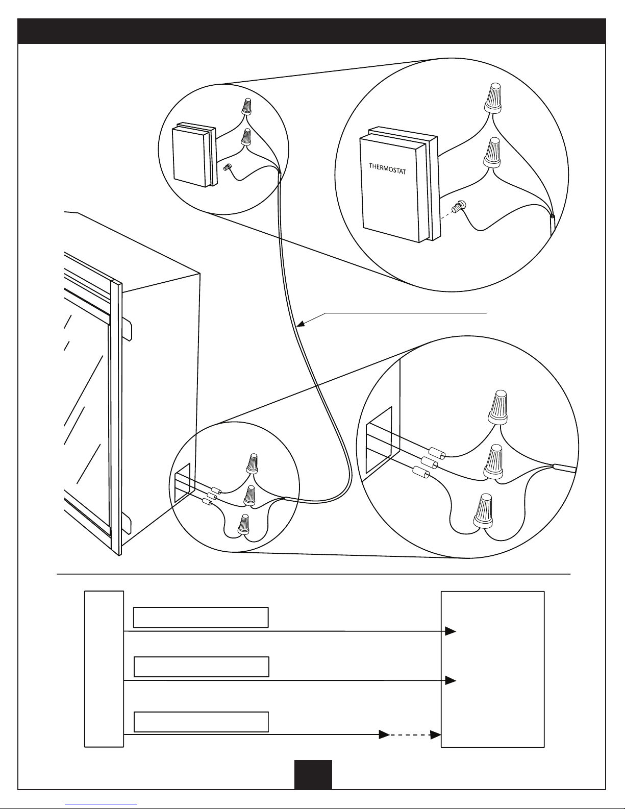
T 2 - FIL ROUGE
BOÎTE DE JONCTION
DU FOYER
LIGNE DE
TENSION
MÉCANIQUE
DU THERMOSTAT
MURAL INSTALLÉ
T 1 - FIL ROUGE
T G - FIL VERT
T 2
T 1
T G
2 FIL S CON DUC TEU RS VE NAN T D U T HER MOS TAT M URAL
T 2
T 1
T G
F
I
L
N
O
I
R
F
I
L
B
L
A
N
C
F
I
L
L
A
T
E
R
R
E
F
I
L
R
O
U
G
E
F
I
L
N
O
I
R
Diagramme de connexion des ls : gure 11
F-11
Page 27
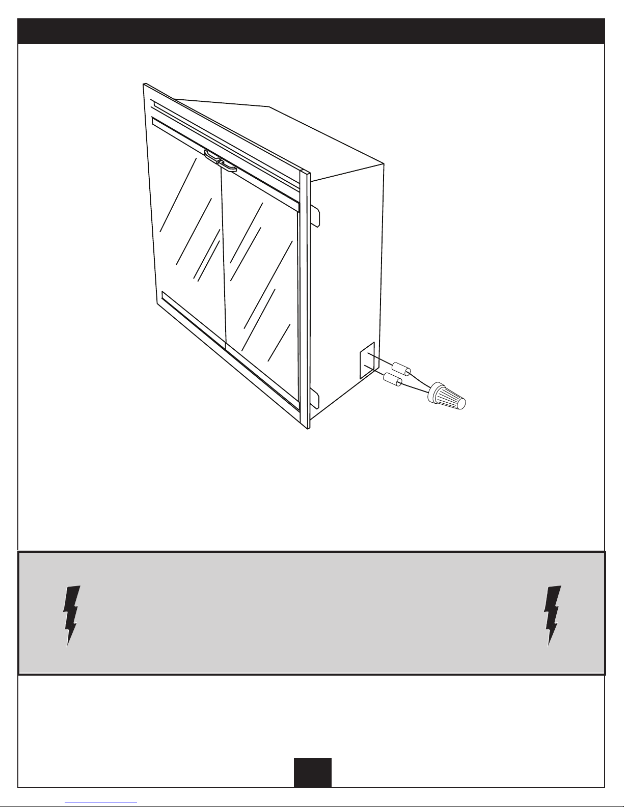
T 2
T 1
Diagramme de connexion des fils: Figure 12
Si vous n’utilisez pas le thermostat externe, les fils T1 et T2 devraient reliés
ensemble, à l’aide d’un capuchon de connexion.
Une fois le câblage terminé, vous devez effectuer un cycle de
test complet pour vérifier le fonctionnement de l’unité AVANT
! !
de refermer le mur ou la zone ou d’y installer des briques ou
de la céramique.
F-12
Page 28
F-13
Page 29
F-14
Page 30

115 S.E. 4th Avenue • Delray Beach, Florida 33483
Une Division de Twin-Star International, Inc.
Phone: 561-330-3201 • Fax: 561-330-3205
www.classicame.com
F-15
Page 31
CHIMENEA ELÉCTRICA EMPOTRADA
GUÍA DE INSTALACIÓN
NÚMEROS DE MODELOS:
33EB304GRS
39EB364GRS
45EB424GRS
INFORMACIÓN SOBRE SEGURIDAD PARA EL CONSUMIDOR
LEA ESTE MANUAL ANTES DE INSTALAR EL APARATO
ADVERTENCIA
EN CASO DE NO SEGUIR LA INFORMACIÓN EN ESTE MANUAL, PODRÍA OCURRIR
UNA DESCARGA ELÉCTRICA O INCENDIO Y, COMO CONSECUENCIA, DAÑOS A
LA PROPIEDAD, LESIONES PERSONALES O LA PÉRDIDA DE LA VIDA.
NO GUARDE NI USE GASOLINA NI OTROS VAPORES Y LÍQUIDOS INFLAMABLES
EN LA CERCANÍA DE ESTE APARATO, NI DE CUALQUIER OTRO.
Gracias y felicitaciones por su adquisición de una chimenea Classic Flame.
Lea las instrucciones de instalación antes de instalar y operar este aparato.
IMPORTANTE: Lea todas las instrucciones y advertencias con detenimiento antes de
comenzar la instalación. Si no se siguen las instrucciones, podría provocarse riesgo
rde descarga eléctrica, incendio o lesiones
y, además, la garantía perdería validez.
Para el servicio a la clientela:
Correo eléctrico: [email protected]
En inglés, llame a: 866-661-1218
En francés, llame a: 866-374-9203
En español, llame a: 866-661-1218
S-1
Twin-Star International, Inc.
Delray Beach, FL 33483
Made in China
Printed in China
Page 32
APROBACIONES DE CÓDIGOS Y LISTAS
LA SERIE DE CAJA DE LOS FABRICANTES SE HA PROBADO Y APROBADO DE ACUERDO
CON LAS NORMAS CSA, Nº 220391 PARA LOS CALENTADORES DE INTERIOR
ELÉCTRICOS FIJOS Y ESPECÍFICOS PARA UNA UBICACIÓN.
ESPECIFICACIONES DEL MODELO
NÚMERO DEL
MODELO DESCRIPCIÓN VOLTAJE
33EB304GRS 33” ESTÁNDAR 120/208/240 1440/2100/2800 SÍ 12.00/10.10/11.67
39EB364GRS
45EB424GRS
39” ESTÁNDAR
45” ESTÁNDAR
120/208/240
120/208/240
VATIOS DE
POTENCIA
NOMINAL
1440/2100/2800
1440/2100/2800
CONTROL
REMOTO AMPERAJE
SÍ
SÍ
12.00/10.10/11.67
12.00/10.10/11.67
¡¡¡ADVERTENCIA!!!
LA INSTALACIÓN DE LA CHIMENEA DEBE CUMPLIR CON LOS CÓDIGOS ELÉCTRICOS
Y LOS REQUISITOS DE SERVICIOS LOCALES O NACIONALES CORRESPONDIENTES.
ESTA INSTALACIÓN DEBE ESTAR A CARGO DE PERSONAL DEBIDAMENTE
CALIFICADO SEGÚN LO EXIJA LA LEY.
DESCRIPCIÓN GENERAL DE LA INSTALACIÓN PASO A PASO
(Lea todas las instrucciones antes de efectuar la instalación)
1) Realice un bosquejo del marco siguiendo
las dimensiones recomendadas.
(Vea la figura 1).
2) Deje un mínimo de 8 pulgadas de cable
de servicio para conectar el cable de suministro de energía a la caja de conexiones
de la chimenea al realizar la instalación
antes de la pared final. Deje hasta 4 pies de
cable de servicio para conectar el cable de
suministro de energía a la caja de
conexiones en la chimenea después de la
pared final.
3) Quite la funda exterior y despoje los con-
ductores individuales a ½”del extremo.
4) Afloje el tornillo que ajusta la tapa de la
caja de conexiones y quítela.
5) Coloque la unidad en posición en la
abertura del marco, nivélela con cuñas si es
necesario y sujétela al marco por medio de
las bridas de montaje provistas
(consulte la Sección 3).
6) Coloque el cableado a un circuito dedicado
con fusibles debidamente colocados con
un índice de 15 amperios para el voltaje
apropiado (120, 208/240).
(Consulte la tabla anterior).
7) Instale el termostato de pared como se
explica en la página 10, sección E.
8) Coloque todas las conexiones dentro de la
caja de conexiones. Asegure la tapa de la
caja sobre la unidad. Al instalar una abrazadera de cables, cerciórese de que agarre
sólo la funda del cable de servicio y del
cable del termostato.
!ADVERTENCIA SOBRE LA SELECCIÓN DE ALIMENTACIÓN!
Esta unidad trae cableado de fábrica para suministro de energía
de 240 voltios. Si se requiere el funcionamiento a 120
! !
conectados a la parte posterior de la caja de conexiones para un fácil acceso.
voltios, deslice el interruptor de voltaje y reconfigure el cableado
según corresponda (vea la figura 2). Los cables L1, L2, N y G están
S-2
Page 33
D
E
F
G
H
I
J
L
K
M
Sección 1: Marco
Esta chimenea está diseñada sin holgura. No
se debe apoyar ningún material combustible
sobre la superficie de la chimenea, pero sí se
pueden colocar a la orilla de la unidad.
MODELO A B C D E F G H I J K L M
33EB304GRS 15.0” 33.0” 29” 28.5” 23.0” 32.8” 29.6” 18.25” 23.6” 14.3” 49.0” 34.7” 34.7”
39EB364GRS
45EB424GRS
16.0”
16.0”
39.0”
45.0”
33”
33”
32.7”
32.7”
27.2”
27.2”
38.7”
44.7”
Se proporcionan cuatro bridas a los lados de
la unidad para facilitar la instalación.
La barrera de aislamiento y vapor se debe ubicar a 2 pulgadas de la unidad, como mínimo.
36.0”
41.9”
22.0”
28.1”
27.6”
28.0
15.3”
”
15.3”
55.0”
61.0”
38.9”
43.1”
38.9”
43.1”
Especificaciones del marco: Figura 1
Sección 2: Especificaciones del cable de suministro de energía recomendado
Para las instalaciones de 120 voltios, uti-
lice un cable de cubierta no metálica, de dos
conductores con cable a tierra (3 cables en
total) para el suministro de energía de entrada
en las chimeneas. Utilice el cable apropiado
que cumpla con los códigos eléctricos locales
y nacionales para el consumo de potencia
nominal.
Para las instalaciones de 208/240 voltios,
utilice un cable de cubierta no metálica, de
tres conductores con cable a tierra (4 cables
en total) para el suministro de energía de
entrada en los hogares. Utilice el cable
apropiado que cumpla con los códigos
eléctricos locales y nacionales para el
consumo de potencia nominal.
Se recomienda utilizar un cable de cubierta
no metálica, de dos conductores con cable a
tierra (3 cables en total) al instalar un termostato montado en la pared para usar en los
hogares.
Requisitos para cables y fusibles
recomendados
Utilice el cable apropiado que cumpla con los
códigos eléctricos locales y nacionales para
el consumo de potencia nominal. Todos los
cables deben ser de calibre 12 con un interruptor dedicado de 15 amperios.
S-3
Page 34
115
230
Sección 3: Ubicación del interruptor selector de voltaje
Importante:
Asegúrese de que el voltaje del suministro
de energía de entrada coincida con la
configuración del interruptor selector
de voltaje.!!!!!!
El interruptor selector de voltaje está ubicado
dentro del panel de escape en el ángulo superior izquierdo. Inserte con cuidado un destornillador de cabeza plana dentro del panel de
escape, a través del orificio en la malla, para
cambiar el interruptor de 240 voltios (posición
de 230) a 120 voltios (posición de 115). La
unidad viene con el interruptor en la posición
de 230 V.
Interruptor selector de voltaje: Figura 2
Precaución:
Cuando cambie el interruptor selector de
voltaje de 240 voltios a 120 voltios,
cerciórese de que el suministro de energía
esté apagado.
Al cablear la unidad para 208/240 voltios, el
interruptor selector de voltaje debe estar en la
posición de 230 voltios. (Vea la figura 2).
Cuando se cablee la unidad para 120 voltios,
el interruptor selector de voltaje debe estar en
la posición de 115 voltios. (Vea la figura 2).
S-4
Page 35
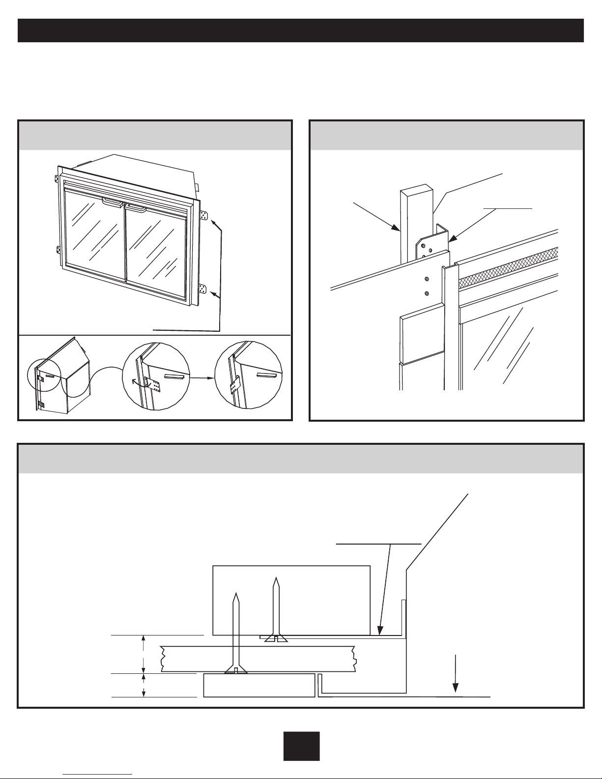
TNOM ED SADIRB JA E
TACO
MADERA O METAL
BRIDA DE MONTAJE
AP EN L ED OSEY T/ A ACORRALB
AB L ASOD
ED MÁREC CI A
PANEL DE YESO TABLARROCA
BALDOSA DE CERÁMICA
TACO
9/16”
3/8”
BRIDA DE MONTAJE
VISTA
SUPERIOR
DEL HOGAR
FRENTE
Sección 4: Bridas de montaje
Hay dos bridas de montaje ubicadas a cada lado de la chimenea. A fin de facilitar el traslado,
se elaboran bridas de montaje planas. Doble las bridas de montaje 90º con la ayuda de una
herramienta adecuada antes de realizar la instalación. (Vea la figura 3)
Ubicación de la brida de montaje: Figura 3
90
o
Doblar 90º
hacia afuera
Ilustración
tras doblar 90º
Brida de montaje y pared: Figura 4
Tolerancias de montaje – Vista superior: Figura 5
S-5
Page 36
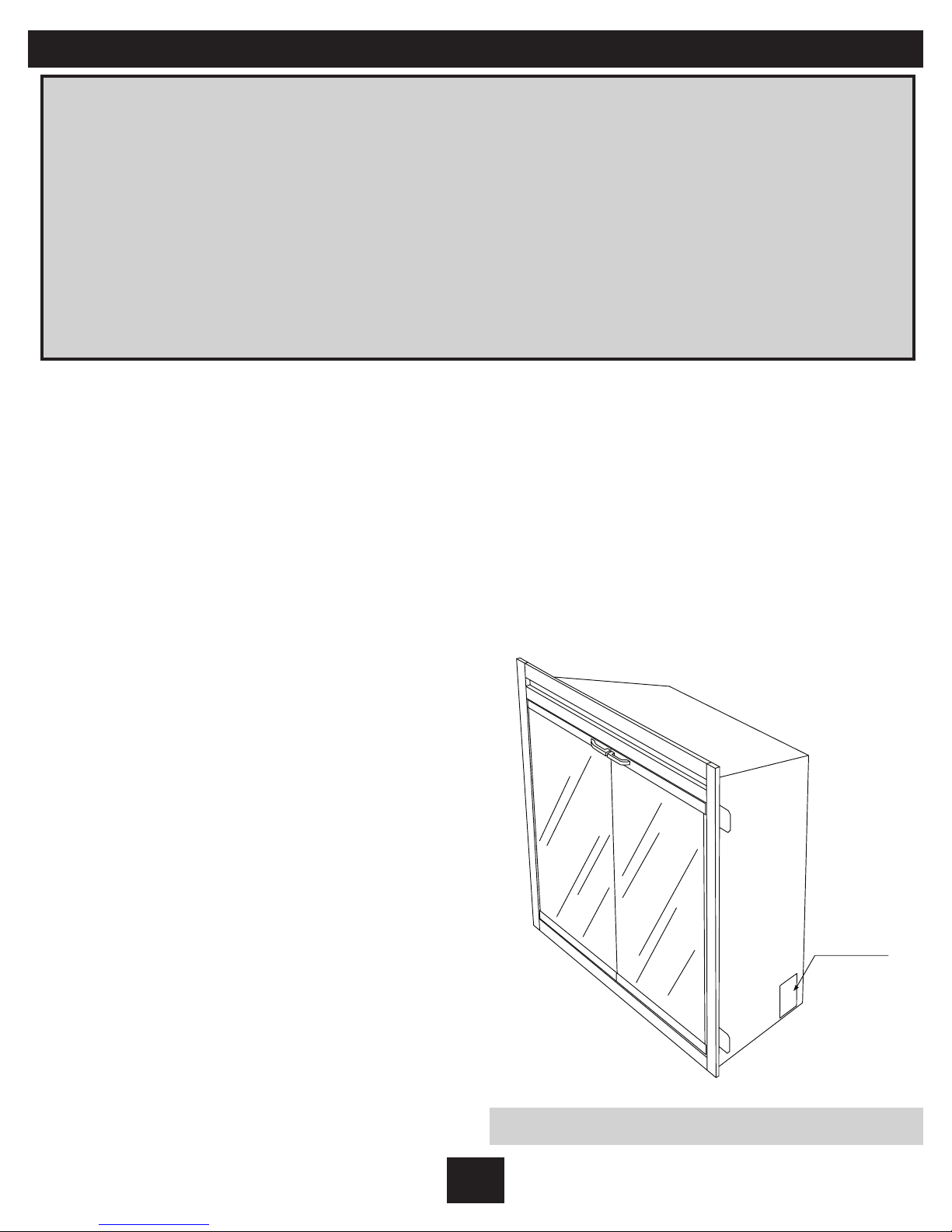
CAJA DE CONEXIONES
Sección 5: Instrucciones de instalación para 120 voltios
Importante
• La unidad viene configurada de fábrica
para operar con 240 voltios.
• Utilice un cable de 2 conductores con
puesta a tierra (3 cables en total) desde
el suministro de energía (panel del
interruptor) hasta la caja de conexiones
de la unidad.
1. Localice el interruptor selector de voltaje
dentro del panel de escape en el ángulo
superior izquierdo de la unidad. (Vea la
figura 2 en la página 3).
2. Confirme que el interruptor esté configu-
rado en 120 voltios (en el interruptor dice
115 voltios).
3. Afloje el tornillo que ajusta la tapa de la
caja de conexiones y quítela.
4. Retire los separadores (si es necesario)
o utilice una abrazadera de cables
(no provista).
5. Saque los cuatro cables identificados
como L1, L2, N y G.
6. Conecte el cable L1 negro de la unidad al
cable L1 negro del suministro de energía.
7. Conecte el cable L2 rojo y el cable N de
la unidad al cable N del suministro de
energía.
8. Conecte el cable a tierra verde de la
unidad a la puesta a tierra del suministro
de energía.
9. Asegúrese de que todas las conexiones
estén ajustadas.
10. Vuelva a insertar todo el cableado en la
unidad y asegúrelo con una abrazadera
de cables.
• Se debe finalizar todo el cableado antes
de instalar la unidad.
• Asegúrese de que el interruptor selector
de voltaje esté en la posición correcta
para el voltaje de suministro requerido
antes de conectar la unidad al suministro
de energía.
Localizador de la caja de conexiones: Figura 6
S-6
Page 37
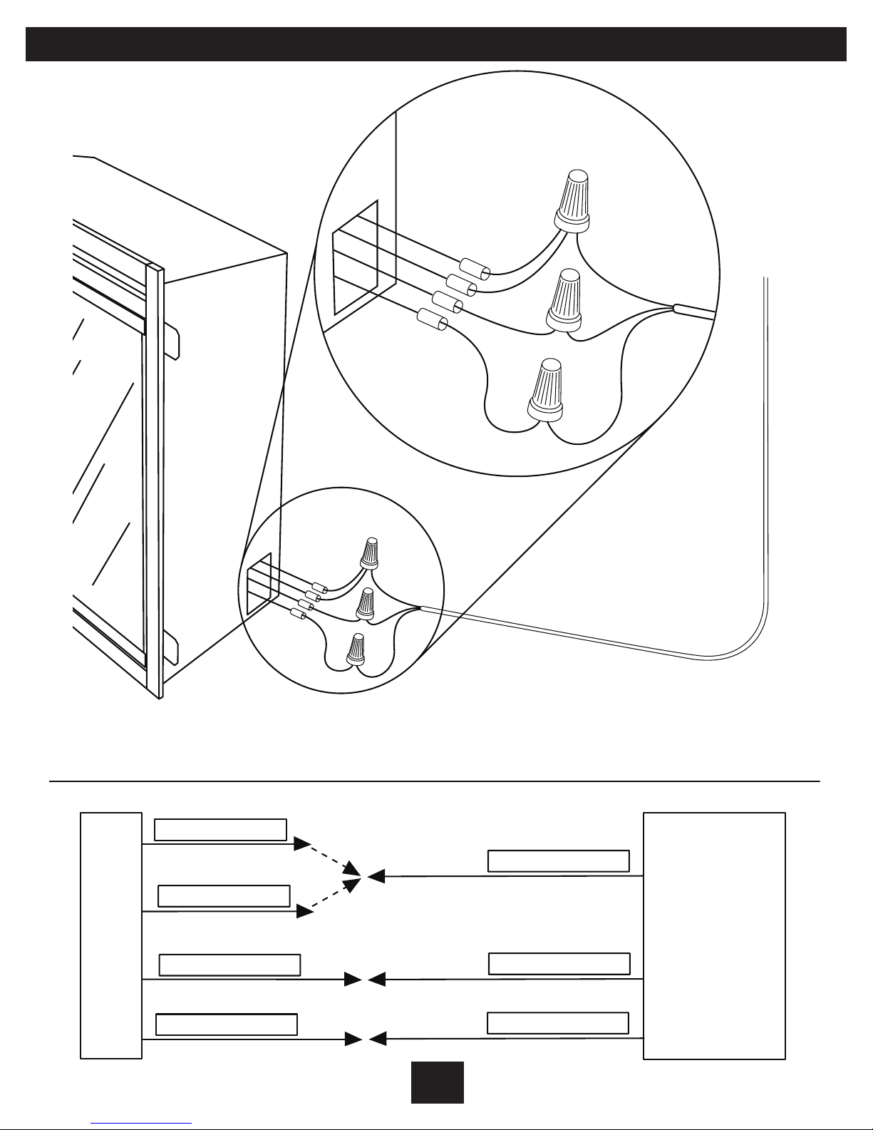
N - CABLE BLANCO
L2 - CABLE ROJO
L1- CABLE NEGRO
G- CABLE VERDE
N - CABLE BLANCO
L1 - CABLE NEGRO
G - CABLE VERDE
CAJA DE CONEXIONES
DE LA CHIMENEA
SUMINISTRO
DE ENERGÍA
DE 120 VOLTIOS
PANEL DEL
INTERRUPTOR
N
L2
L1
G
N
L2
L1
G
Diagrama de conexión de cables: Figura 7
S-7
Page 38
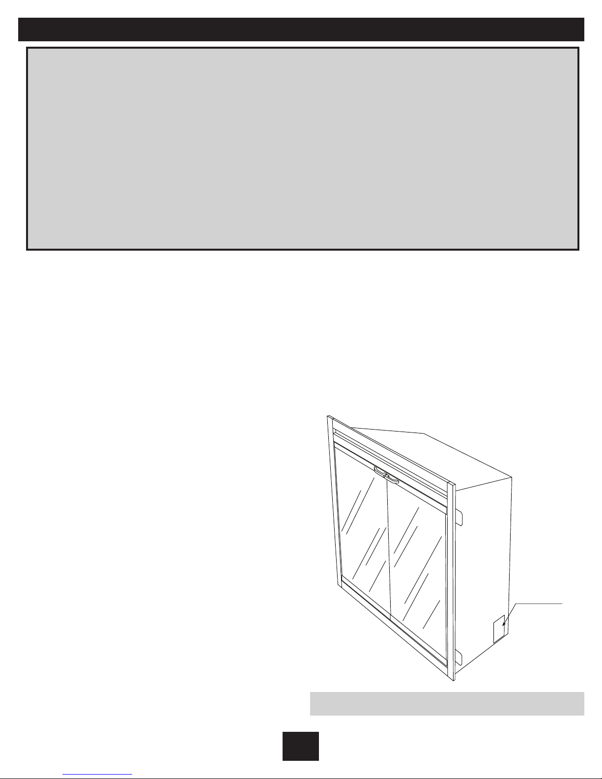
CAJA DE CONEXIONES
Sección 6: Instrucciones de instalación para 240 voltios
Importante
• La unidad viene configurada de fábrica
para operar con 240 voltios. Debe fijar el
interruptor selector de voltaje en 240
voltios (en el interruptor dice 230 voltios).
• Utilice un cable de 3 conductores con
puesta a tierra (4 cables en total) desde
el suministro de energía (panel del inter-
ruptor) hasta la caja de conexiones de la
unidad.
1. Localice el interruptor selector de voltaje
dentro del panel de escape en el ángulo
superior izquierdo de la unidad. (Vea la
figura 2 en la página 3).
2. Confirme que el interruptor esté configu-
rado en 240 voltios (en el interruptor
dice 230 voltios).
• Se debe finalizar todo el cableado antes
de instalar la unidad.
• Asegúrese de que el interruptor selector
de voltaje esté en la posición correcta
para el voltaje de suministro requerido
antes de conectar la unidad al suministro
de energía.
10. Asegúrese de que todas las conexiones
estén ajustadas.
11. Vuelva a insertar todo el cableado en la
unidad y asegúrelo con una abrazadera
de cables.
3. Afloje el tornillo que ajusta la tapa de la
caja de conexiones y quítela.
4. Retire los separadores (si es necesario)
o utilice una abrazadera de cables
(no provista).
5. Saque los cuatro cables identificados
como L1, L2, N y G.
6. Conecte el cable L1 negro de la unidad
al cable L1 negro del suministro de
energía
7. Conecte el cable L2 rojo de la unidad al
cable L2 rojo del suministro de energía.
8. Conecte el cable N blanco de la unidad
al cable N blanco del suministro de
energía.
9. Conecte el cable a tierra verde de la
unidad a la puesta a tierra del suministro
de energía.
Junction Box Locator: Figure 8
S-8
Page 39
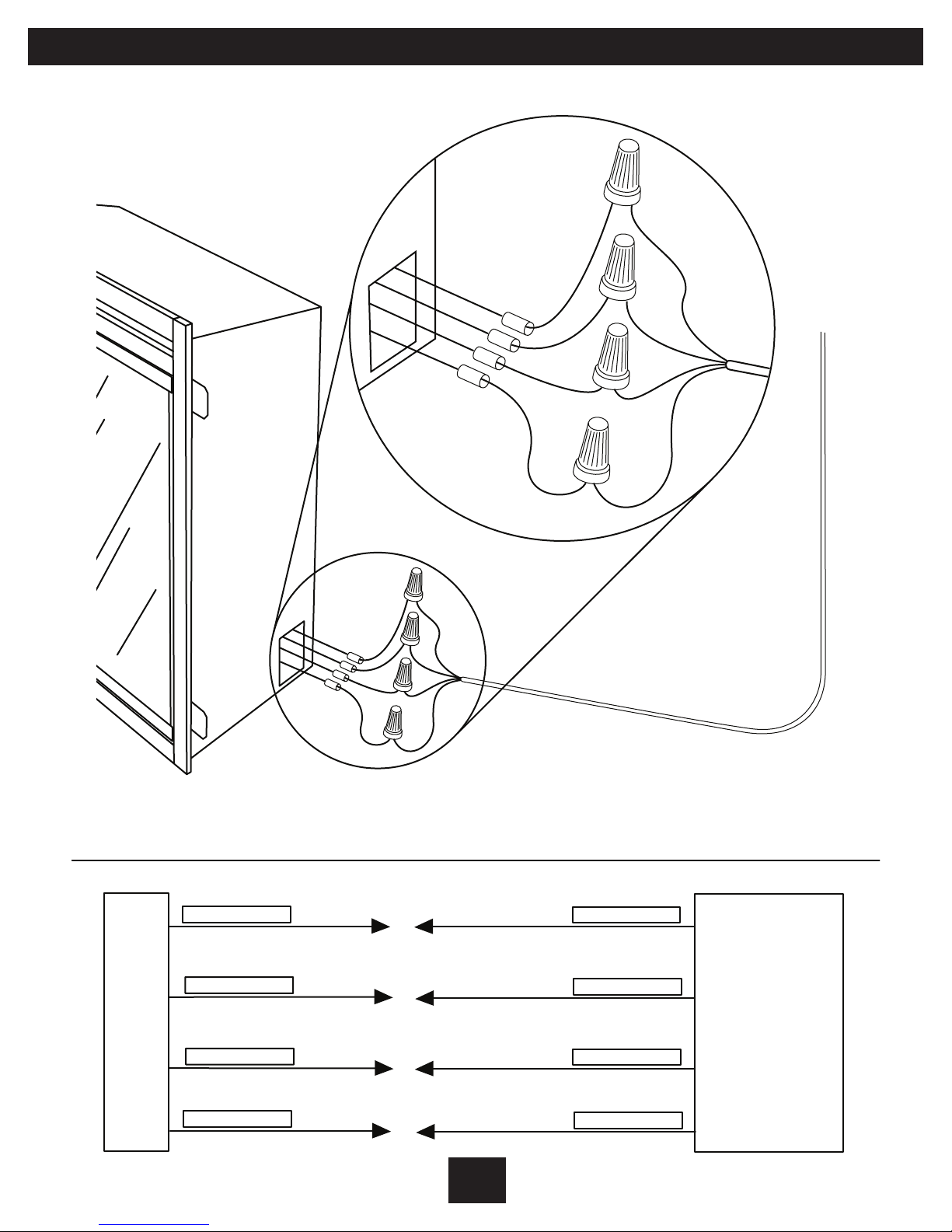
N - CABLE BLANCO
L2 - CABLE ROJO
L1- CABLE NEGRO
G- CABLE VERDE
N- CABLE BLANCO
L1 - CABLE NEGRO
G - CABLE VERDE
CAJA DE CONEXIONES
DE LA CHIMENEA
SUMINISTRO
DE ENERGÍA
DE 240 VOLTIOS
PANEL DEL
INTERRUPTOR
L2 - CABLE ROJO
N
L2
L1
G
N
L2
L1
G
Diagrama de conexión de cables: Figura 9
S-9
Page 40
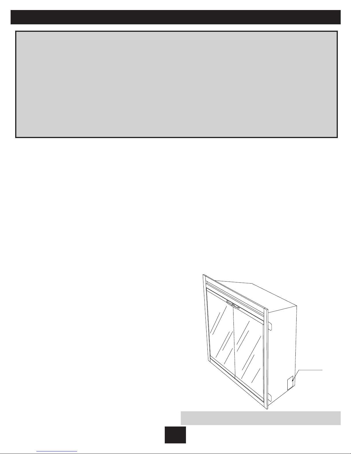
JUNCTION BOX
Sección 7: Cableado del termostato montado en la pared para 120/240 voltios
ATENCIÓN
• Instale la conexión del suministro princi pal con el voltaje apropiado como gura
en la Sección C o la Sección D.
• Coloque un cable de 2 conductores con
puesta a tierra (3 cables en total) desde la
caja de pared del termostat
o hasta la caja
de conexiones en la unidad.
1. Aoje el tornillo que ajusta la tapa de la
caja de conexiones y quítela.
2. Retire los separadores (si es necesario) o
utilice la abrazadera de cables provista.
3. Saque los tres cables identicados como
T1, T2, y TG (rojo, rojo y verde).
4. Quite el conector de cable y separe los
cables identicados como T1 y T2.
5. Conecte el cable T1 (rojo) de la unidad al
cable blanco (neutral) de la caja del
termostato de pared mediante un
conector de cable (no provisto).
• El cableado del termostato debe estar
terminado antes de montar la unidad.
• Las siguientes instrucciones de insta-
lación corresponden a un t
ermostato
unipolar.
10. Conecte el otro extremo del cable verde
(puesta a tierra) de la caja de pared del
termostato a la placa trasera del termo
stato montado en la pared con un tornillo
de puesta a tierra.
11. Asegúrese de que todas las conexiones
estén ajustadas.
12. Insert
e todo el cableado del termostato
montado en la pared en la caja de pared.
13. Vuelva a insertar todo el cableado en la
unidad y asegúrelo con una abrazadera
de cables.
6. Conecte el otro extremo del cable blanco
(neutro) de la caja de pared del termo-
stato al cable rojo del termostato de
pared.
7. Conecte el cable T2 (rojo) de la unidad
al cable negro de la caja de pared del
termostato mediante un conector de
cable (no provisto).
8. Conecte el otro extremo del cable negro
de la caja de pared del termostato al
cable negro del termostato de pared.
9. Conecte el cable TG verde (puesta a tierra)
de la unidad al cable verde (puesta a
tierra) de la caja de pared del termostato
mediante un conector de cable
(no provisto).
Localizador de la caja de conexiones: Figura 10
S-10
Page 41
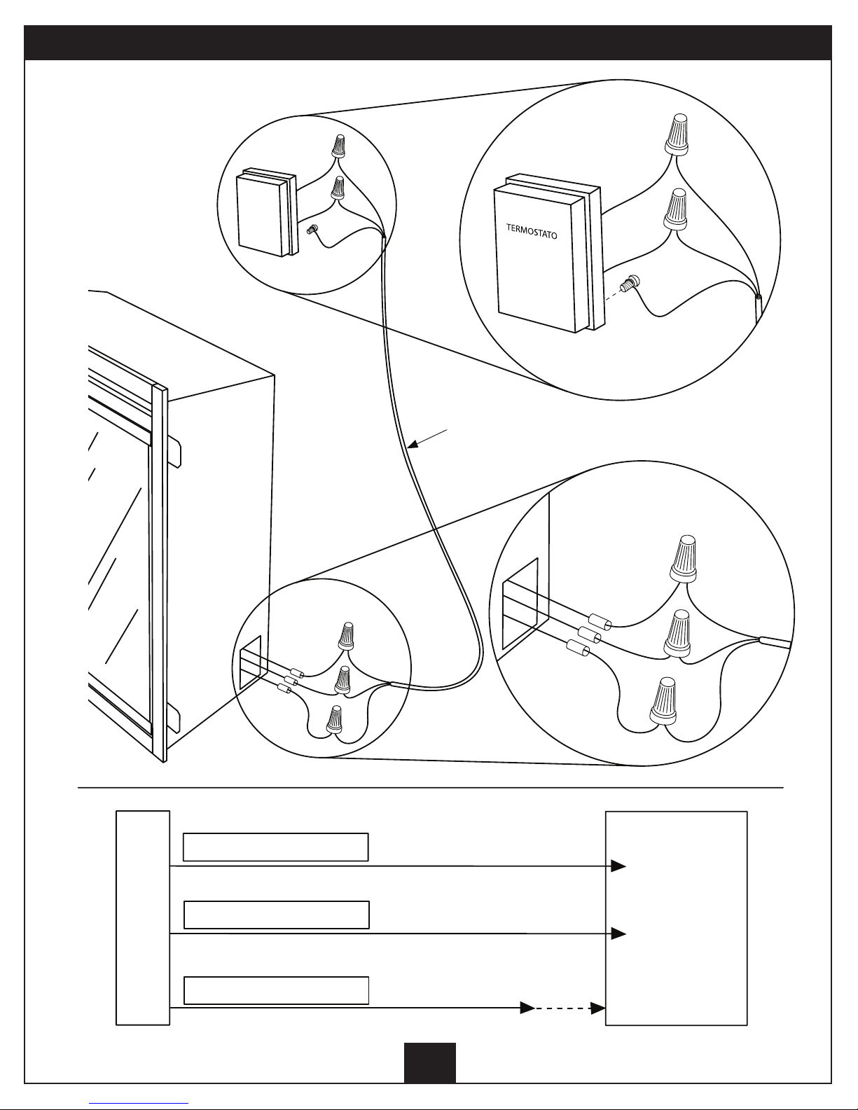
T 2 - CABLE ROJO
CHIMENEA-
CAJA DE CONEXIONES
TERMOSTATO
CON VOLTAJE
DE LÍNEA
MECÁNICO
MONTADO
EN LA PARED
T 1 - CABLE ROJO
T G - CABLE VERDE
T 2
T 1
T G
CA BLE DE 2 CO NDUCT ORE S D ESDE EL TE RMO STATO DE PAR ED
T 2
T 1
T G
C
A
B
L
E
N
E
G
R
O
C
A
B
L
E
B
L
A
N
C
O
C
A
B
L
E
D
E
T
I
E
R
R
A
C
A
B
L
E
R
O
J
O
C
A
B
L
E
N
E
G
R
O
Diagrama de conexión de cables: Figura 11
S-11
Page 42
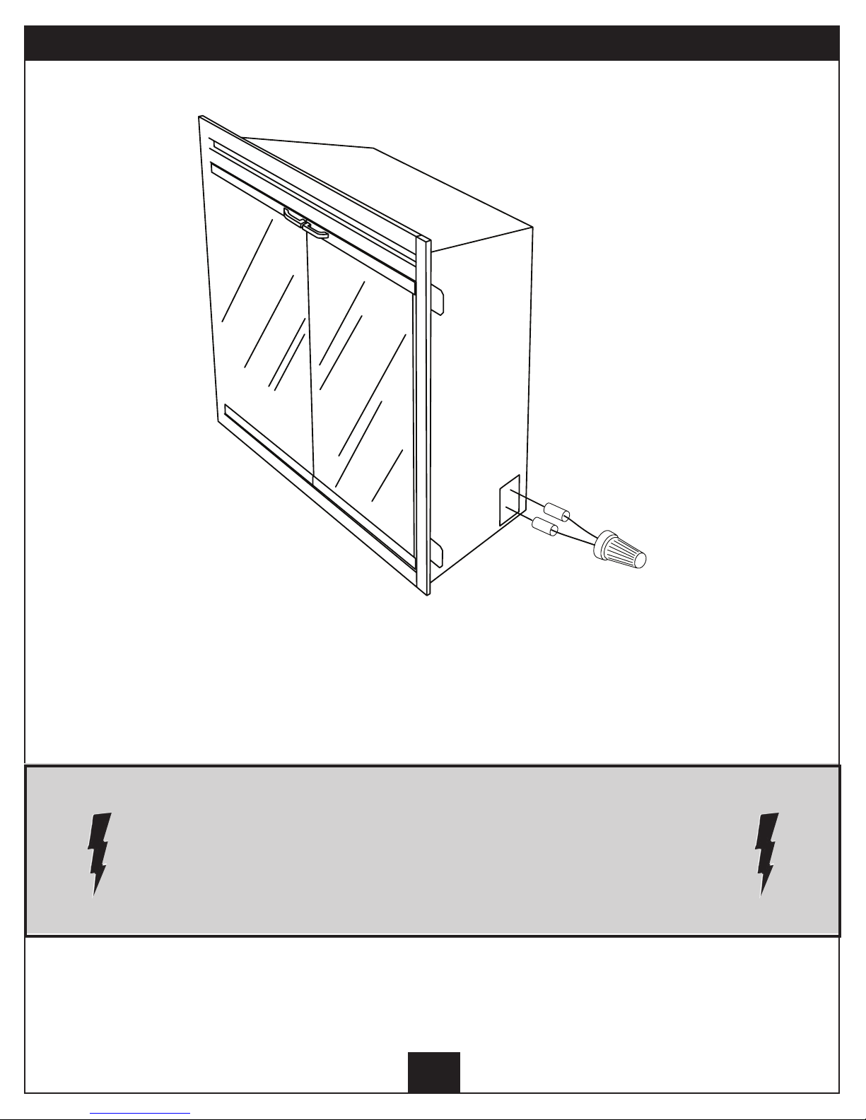
T 2
T 1
Diagrama de conexión de cables : Figura 12
Si no se utilizará el termostato externo, el cable T1 y el cable T2 deben
unirse mediante un empalme plástico.
Una vez que el cableado esté finalizado, se debe realizar un
“ciclo de pruebas” completo para verificar el funcionamiento de
! !
la unidad ANTES de tapar el área, o colocar ladrillos o azulejos
en la pared.
S-12
Page 43
S-13
Page 44
S-14
Page 45

115 S.E. 4th Avenue • Delray Beach, Florida 33483
Una División de Twin-Star International, Inc.
Phone: 561-330-3201 • Fax: 561-330-3205
www.classicame.com
S-15
 Loading...