

Classicflame 39EB500GRS, 39EB500ARA, 39EB500GRA User Manual

INSTRUCTION MANUAL ENCLOSED
MANUEL D’INSTRUCTION À L’INTÉRIEUR
MANUAL DE INSTRUCCIONES ADJUNTO
STOP
STOP
ATTENTION
IF YOU HAVE ANY PROBLEMS OR QUESTIONS, EMAIL
OR CALL CUSTOMER SERVICE BEFORE YOU RETURN
THIS PRODUCT TO THE STORE WHERE IT WAS PURCHASED.
For Customer Service: www.twinstarhome.com
in English Call: 866-661-1218
in Spanish Call: 866-661-1218
in French Call: 866-374-9203
PARE
PARE
ATENCIÓN
SI TIENE ALGÚN PROBLEMA O PREGUNTAS,
ENVÍE UN MENSAJE DE CORREO ELECTRÓNICO O LLAME AL SERVICIO
DE ATENCIÓN AL CLIENTE ANTES DE DEVOLVER
ESTE PRODUCTO A LA TIENDA EN LA QUE LO COMPRÓ.
Servicio de atención al cliente: www.twinstarhome.com
Línea para llamadas en inglés: 866-661-1218
Línea para llamadas en español: 866-661-1218
Línea para llamadas en francés: 866-374-9203
ARRÊT
ATTENTION
ARRÊT
SI VOUS AVEZ DES PROBLÈMES OU DES QUESTIONS,
ENVOYEZ UN COURRIEL AU SERVICE À LA CLIENTÈLE OU APPELEZ LE
SERVICE À LA CLIENTÈLE AVANT DE RETOURNER
CE PRODUIT OÙ VOUS L’AVEZ ACHETÉ.
Pour le service à la clientèle : www.twinstarhome.com
pour le service en anglais, appelez au: 866-661-1218
pour le service en espagnol, appelez au: 866-661-1218
pour le service en français, appelez au: 866-374-9203
INSTRUCTION MANUAL ENCLOSED
MANUEL D’INSTRUCTION À L’INTÉRIEUR
MANUAL DE INSTRUCCIONES ADJUNTO
BUILT IN ELECTRIC FIREPLACE
INSTALLATION GUIDE
MODEL NUMBERS:
39EB500ARA
39EB500GRA
39EB500GRS
CONSUMER SAFETY INFORMATION
PLEASE READ THIS MANUAL BEFORE INSTALLING THIS APPLIANCE
WARNING
IF THE INFORMATION IN THIS MANUAL IS NOT FOLLOWED,
AN ELECTRIC SHOCK OR FIRE MAY RESULT CAUSING
PROPERTY DAMAGE, PERSONAL INJURY OR LOSS OF LIFE.
DO NOT STORE OR USE GASOLINE OR OTHER FLAMMABLE
VAPORS AND LIQUIDS IN THE VICINITY OF THIS
OR ANY OTHER APPLIANCE.
Thank you and congratulations on your purchase of a Classic Flame fireplace.
Please read the installation instructions before installing and operating
this appliance.
IMPORTANT: Read all instructions and warnings carefully before starting installation.
Failure to follow these instructions may result in a possible electric shock, fire
hazard and/or injury and will void the warranty.
For Customer Service:
E-Mail: parts@twinstarhome.com
In English Call: 866-661-1218
En Français Call: 866-374-9203
En Español Call: 866-661-1218
E-1
Twin-Star International, Inc.
Delray Beach, FL 33445
U.S.A.
Made in China
Printed in China
© 2011, Twin-Star International, Inc.
LISTINGS AND CODE APPROVALS
THE BUILDERS BOX SERIES HAS BEEN TESTED AND APPROVED IN ACCORDANCE WITH THE
CSA, No.220391, STANDARDS FOR FIXED AND LOCATION
DEDICATED ELECTRIC ROOM HEATERS.
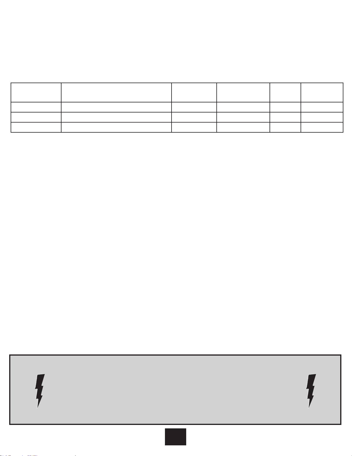
MODEL SPECIFICATIONS
Model Number Description Voltage Watts Amps
39EB500ARA 39”Electric Box without any doors 120/208/240 1440/2100/2800 YES 12/10.1/11.7
39EB500GRA 39”Electric Box with glass front 120/208/240 1440/2100/2800 YES 12/10.1/11.7
39EB500GRS 39”Electric Box with double swing door 120/208/240 1440/2100/2800 YES 12/10.1/11.7
Remote
Control
!!! WARNING !!!
THE INSTALLATION OF THE FIREPLACE UNIT MUST COMPLY WITH THE APPLICABLE
LOCAL AND/ OR NATIONAL ELECTRICAL CODES AND UTILITY REQUIREMENTS.
THIS INSTALLATION SHOULD BE ENTRUSTED TO DULY QUALIFIED
PERSONNEL WHERE REQUIRED BY LAW.
STEP - BY - STEP INSTALLATION OVERVIEW
(please read all instructions before installation)
1) Rough in framing following the
recommended dimensions. (see figure 1)
2) Allow at least 8” of service cable for
connecting power supply wire to junction
box on fireplace insert when installing
before finishing wall. Allow up to 4 feet of
service cable for connecting power supply
wire to junction box on fireplace insert
after finishing wall.
3) Remove the outer jacket and strip the
individual conductors ½” from end.
4) Loosen the screw securing the junction
box cover and remove the cover.
5) Place unit in position in the framed
opening, level with shims if necessary
and attach unit to frame using mounting
flanges provided ( see Section 3).
6) Wire a dedicated, properly fused circuit with
a 15 amp rating for the appropriate voltage
(120, 208/240). (See table above)
7) Place all connections inside the junction
box. Secure the junction box cover on the
unit.
When installing a cable clamp make sure it
grips only the jacket of the service cable
and thermostat wire.
!POWER SELECTION WARNING!
This unit is factory wired for 120 volt power supply.
If 240 volt operation is required, slide the voltage switch
! !
and reconfigure the wiring accordingly (see figure 2).
Wires L1, L2, N & G are attached to the rear of
the junction box for easy access.
E-2
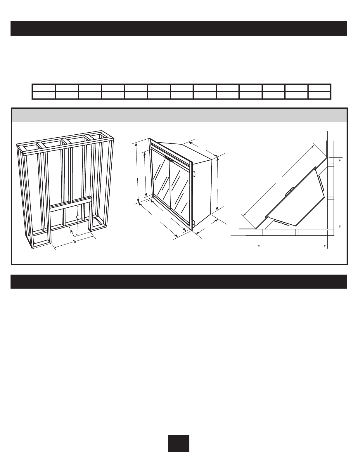
Section 1: Framing
This fireplace is a zero clearance design. No
combustibles can be placed on the top
surface of the fireplace. Combustibles may
be installed to the edge of the unit.
A B C D E F G H I J K L M
16.0” 37.0” 32” 32.4” 27.0” 38.9” 36.0” 22.0” 28.0” 15.6” 55.0” 38.9” 38.9”
Framing Specifications: Figure 1
E
D
F
Four mounting flanges on the sides of the unit
are provided to facilitate installation.
Insulation and vapor barrier should be placed
a minimum of 2 inches from the unit.
H
I
G
J
K
L
Section 2: Recommended Power Supply Wire Specifications
For 120 volt installations use two conductor,
non-metallic sheath cable with ground wire
(3 wires total) for the incoming power supply
on fireplace inserts. Use the appropriate wire
to meet local and national electrical codes for
rated power consumption.
For 208/240 volt installations use three
conductor, non-metallic sheath cable with
ground wire (4 wires total) for the incoming
power supply on fireplace inserts. Use the
appropriate wire to meet local and national
electrical codes for rated power consumption.
M
Two conductor, non-metallic sheath cable with
ground wire (3 wires total) is recommended
for installation of a wall mounted thermostat
for use on fireplace inserts.
Recommended Wire and
Fusing Requirements
Use appropriate wire to meet local and
national electrical codes for rated power consumption. All wire gauges should be
12 gauge with a dedicated 15 amp breaker.
E-3
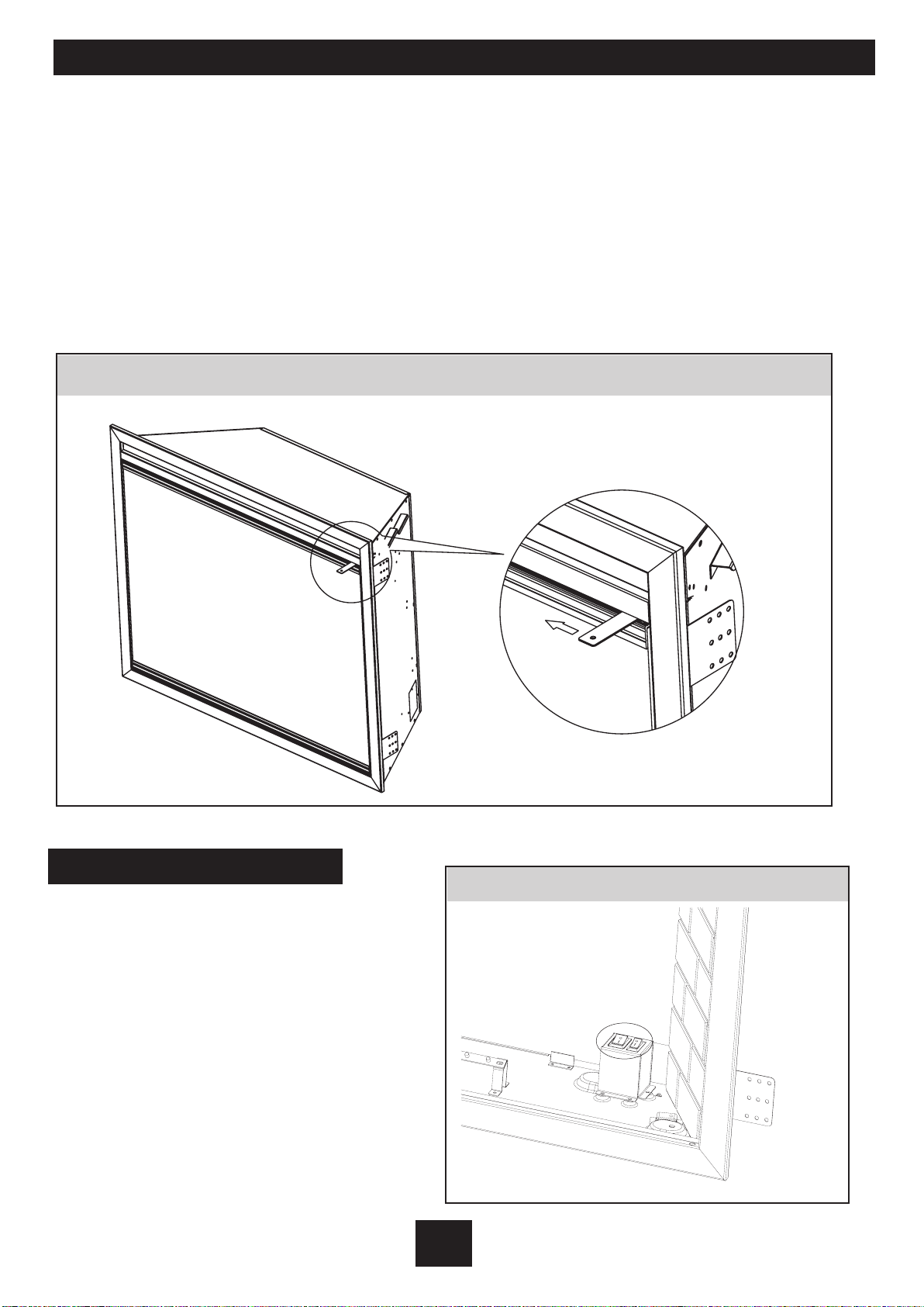
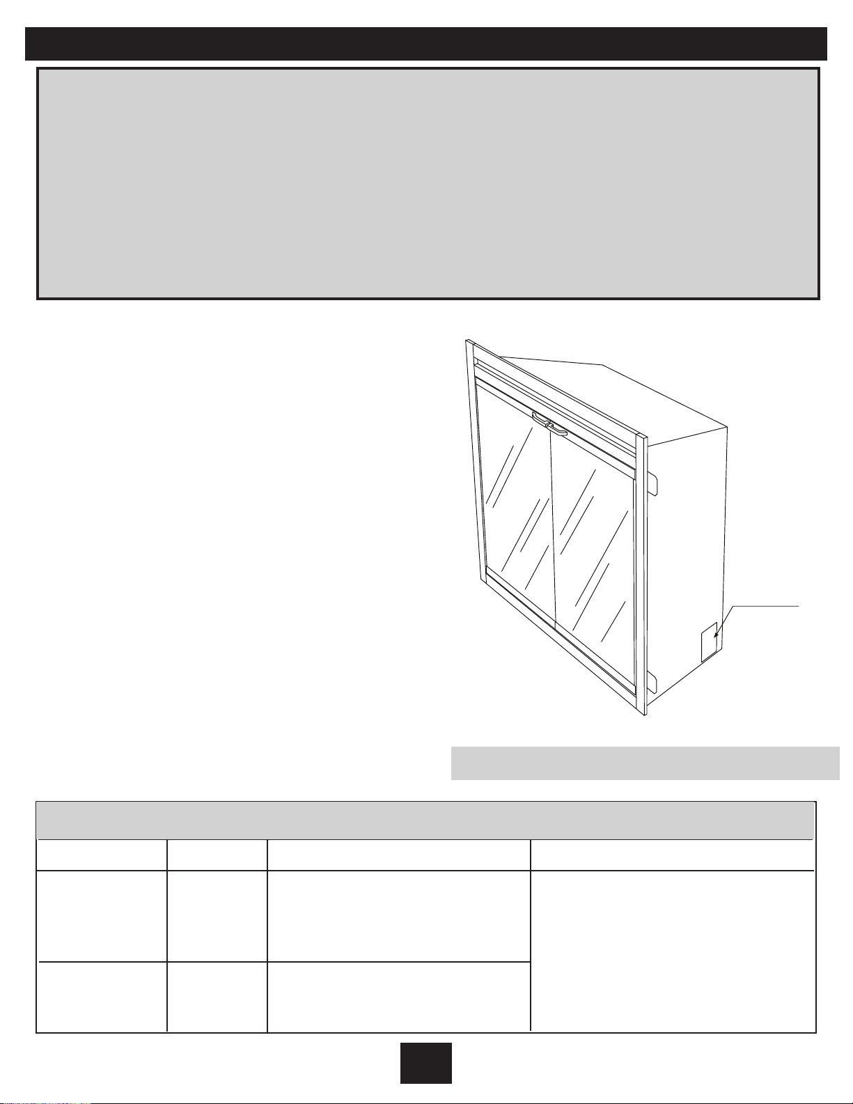
39EB500GRA Single Glass Door Open
The 39EB500GRA with the glass front has concealed latches, to open the glass front follow these steps:
1) There are 2 concealed latches; facing the fireplace the latches are on the upper right and lower right
corner of the glass. The latch positions are illustrated in Figure A.
2) In the gap between the glass frame and the larger fireplace frame there is a small tab that needs to
be moved to open the glass front.
3) Using a household key or small screw driver (not provided) carefully place the key between the glass
frame and fireplace frame as shown in figure B.
4) Using the key move the latch tab left to the open position, illustrated in figure B.
5) The latches are spring loaded, once correctly opened they will hold in the unlocked position.
6) Service or install the fireplace.
7) Close the glass front with the latch tabs in the unlocked position, using a key engage the spring
loaded latch tabs.
Figure A
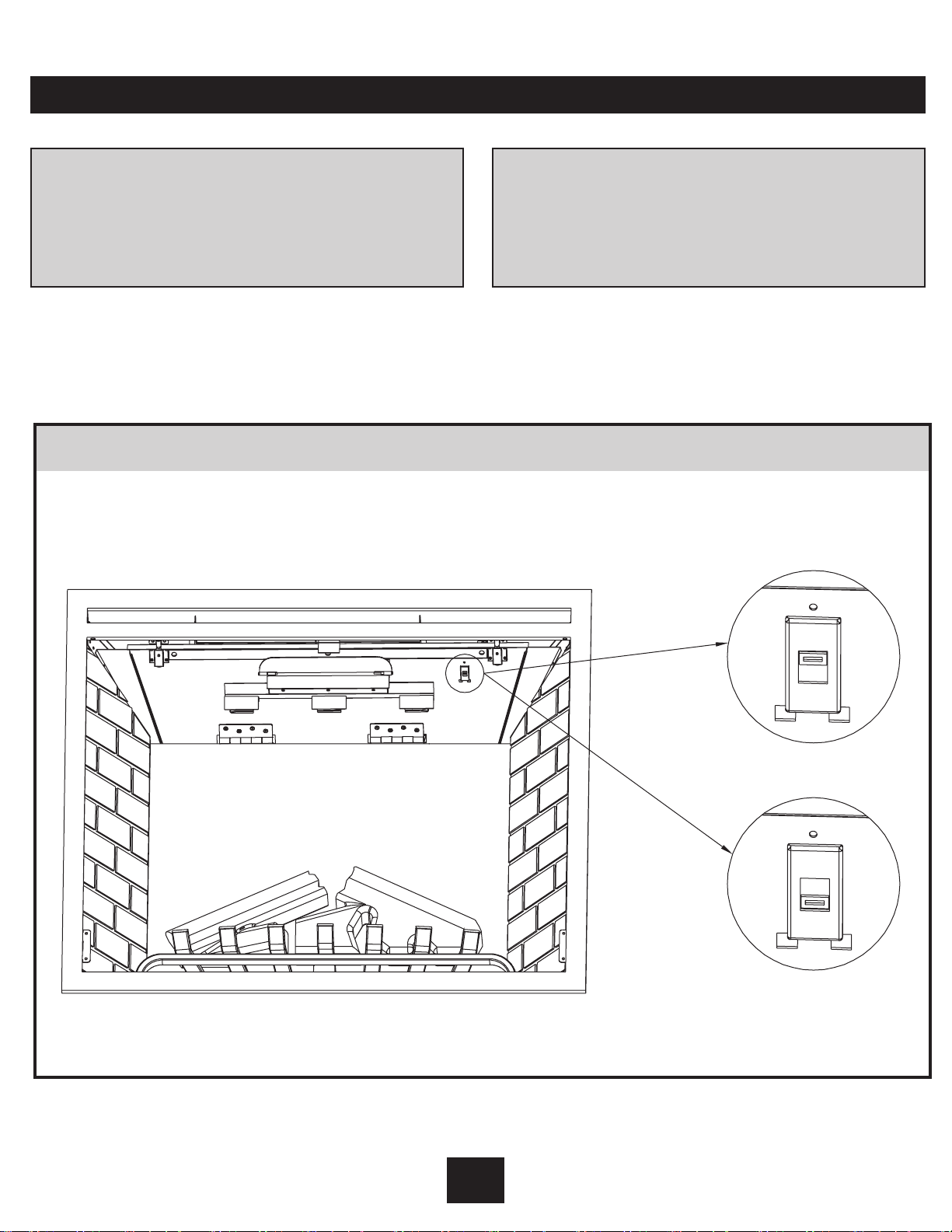
Important Instruction:
The 2 switches (Figure C) located on the right
side of emberbed must be in the on postions
for any functions including the remote to work.
Turn these 2 switches off when servicing this
appliance.
OPEN
KEY (not provided)
Figure B
Figure C
E-4
Section 3: Voltage Selector Switch Location
Important:
Ensure that the incoming power supply
voltage matches the setting of the
voltage selector switch!!!!!!
The voltage selector switch is located behind
the top brick panel on the right hand corner.
When wiring the unit for 208/240 volts the
voltage selector switch should be in the
Voltage Selector Switch: Figure 2
Caution:
When changing the voltage selector switch
from 240 volts to 120 volts ensure that the
power supply is turned off.
230 volt position. (see figure 2)
When wiring the unit for 120 volts the voltage
selector switch should be in the 115 volt
position. (see figure 2)
23 0
11 5
E-5
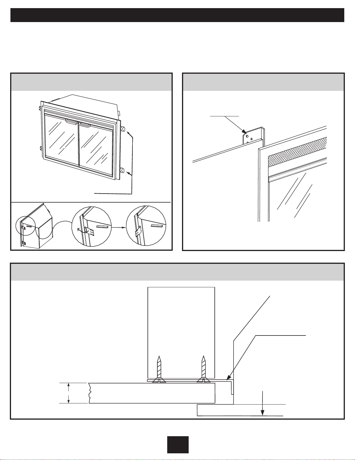
Section 4: Mounting Flanges
There are two mounting flanges located on each side of the fireplace insert. In order to facilitate
the transportation, we make the mounting flanges into flat status.
Please bend the mounting flanges into 90
(please see the figure 3)
o
using suitable hardware before installation.
Mounting Flange Location: Figure 3
GMOUNTIN
EGNALF S
o
90
Bend 90o
to outside
Picture after
bending 90
Wall and Mounting Flange: Figure 4
MOUNTING FLANGE
/ SHEERD WY LLA CORT K
o
5/8”
Mounting Tolerances - Top View: Figure 5
STUD
MOUNTING FLANGE
INSERT
TOP
VIEW
FRONT
DRYWALL / SHEETROCK
E-6
Section 5: 120 Volt Installation Instructions
Important
• The unit is factory configured for 120 volt
operation.
• Use 2 conductor wire with ground (3 wires
total) from the power supply (breaker
panel) to the junction box on the unit.
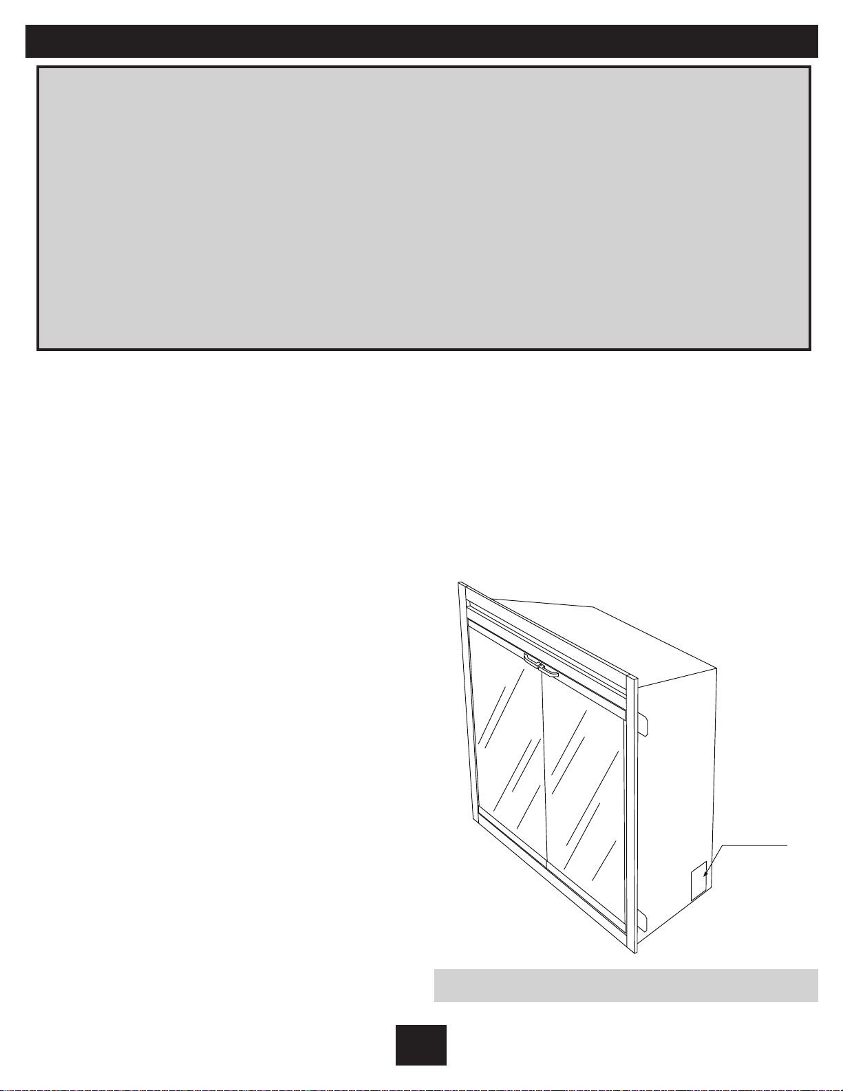
1. Locate voltage selector switch behind
the top brick panel in the right hand
corner.
2. Confirm the switch is set to 120 volt
configuration ( 115 volt is printed on
switch).
3. Loosen the screw securing the junction
box cover and remove the cover.
4. Remove the knockouts (if necessary)
or use a cable clamp (not provided).
5. Pull out the four wires marked L1, L2,
N, and G.
6. Connect the black L1 wire from the unit to
the black L1 from the power supply.
7. Connect the red L2 wire and the N wire
from the unit to the N wire from the
power supply.
8. Connect the green ground wire from the
unit to the ground from the power supply.
9. Ensure that all connections are tight.
10. Insert all the wiring back into the unit and
secure with a cable clamp.
• All wiring must be completed prior to
installing the unit.
• Ensure that the voltage selector switch is
in the proper position for the required
supply voltage prior to connecting the unit
to the power supply.
JUNCTION BOX
Junction Box Locator: Figure 6
Switch Setting
230V
115V
Voltage Selector Switch Troubleshooting
Power Result
The fireplace will function but
the heater will not work
120V
240V
correctly. The heater function
indicator will flash continuously.
The fireplace will not function,
the Function Indicator will
display “UE.”
E-7
Solution
Use the two switches located right
of the emberbed to cut power to the
fireplace then correctly set the
voltage selector switch and turn
back on the power and operate
as normal.
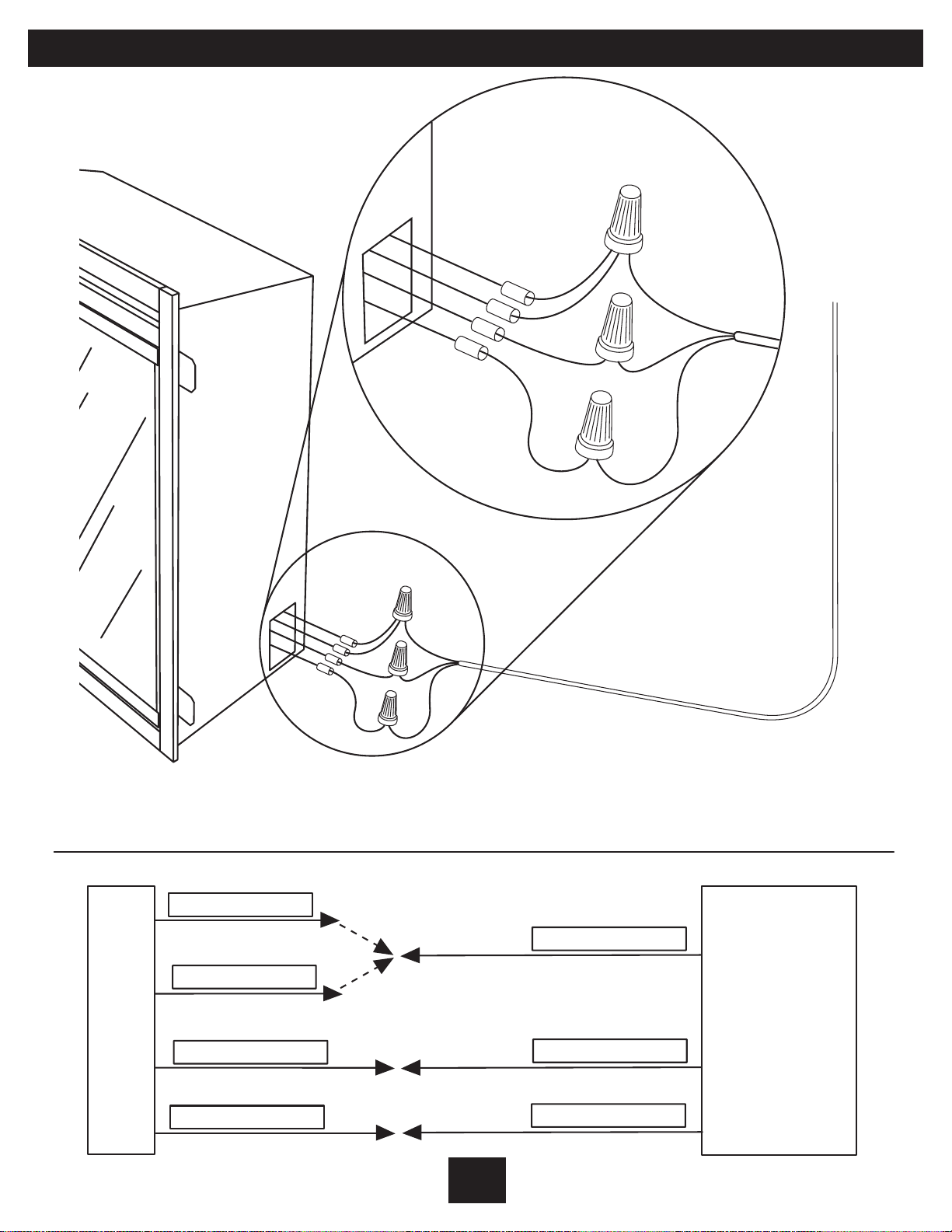
Figure 6: 120V Wire Connection Diagram
N
L2
L1
G
N - WHITE WIRE
L2 - RED WIRE
L1- BLACK WIRE
N
L2
L1
G
N- WHITE WIRE
120 VOLT
POWER SUPPLY
BREAKER
L1 - BLACK WIRE
PANEL
G- GREEN WIRE
G - GREEN WIRE
FIREPLACE -JUNCTION BOX
E-8
Section 7: 240 Volt Installation Instructions
Important
• The unit is factory configured for 120 volt
operation. You must set the voltage
selection switch to 240 volts (230 volt is
printed on the switch.
• Use 3 conductor wire with ground (4 wires
total) from the power supply (breaker
panel) to the junction box on the unit.
1. Locate voltage selector switch behind
the top brick panel in the right hand
corner. . (see figure 2 on page 3)
2. Confirm the switch is set to 240 volt
configuration (230 volt is printed
on switch).
• All wiring must be completed prior to
installing the unit.
• Ensure that the voltage selector switch is
in the proper position for the required
supply voltage prior to connecting the unit
to the power supply.
3. Loosen the screw securing the junction
box cover and remove the cover.
4. Remove the knockouts (if necessary) or
use a cable clamp (not provided).
5. Pull out the four wires marked L1, L2,
N, and G.
6. Connect the black L1 wire from the unit to
the black L1 from the power supply.
7. Connect the red L2 wire from the unit to
the red L2 from the power supply.
8. Connect the white N wire from the unit to
the white N wire from the power supply.
9. Connect the green ground wire from the
unit to the ground from the power supply.
10. Ensure that all connections are tight.
JUNCTION BOX
11. Insert all the wiring back into the unit and
secure with a cable clamp.
Junction Box Locator: Figure 8
E-9
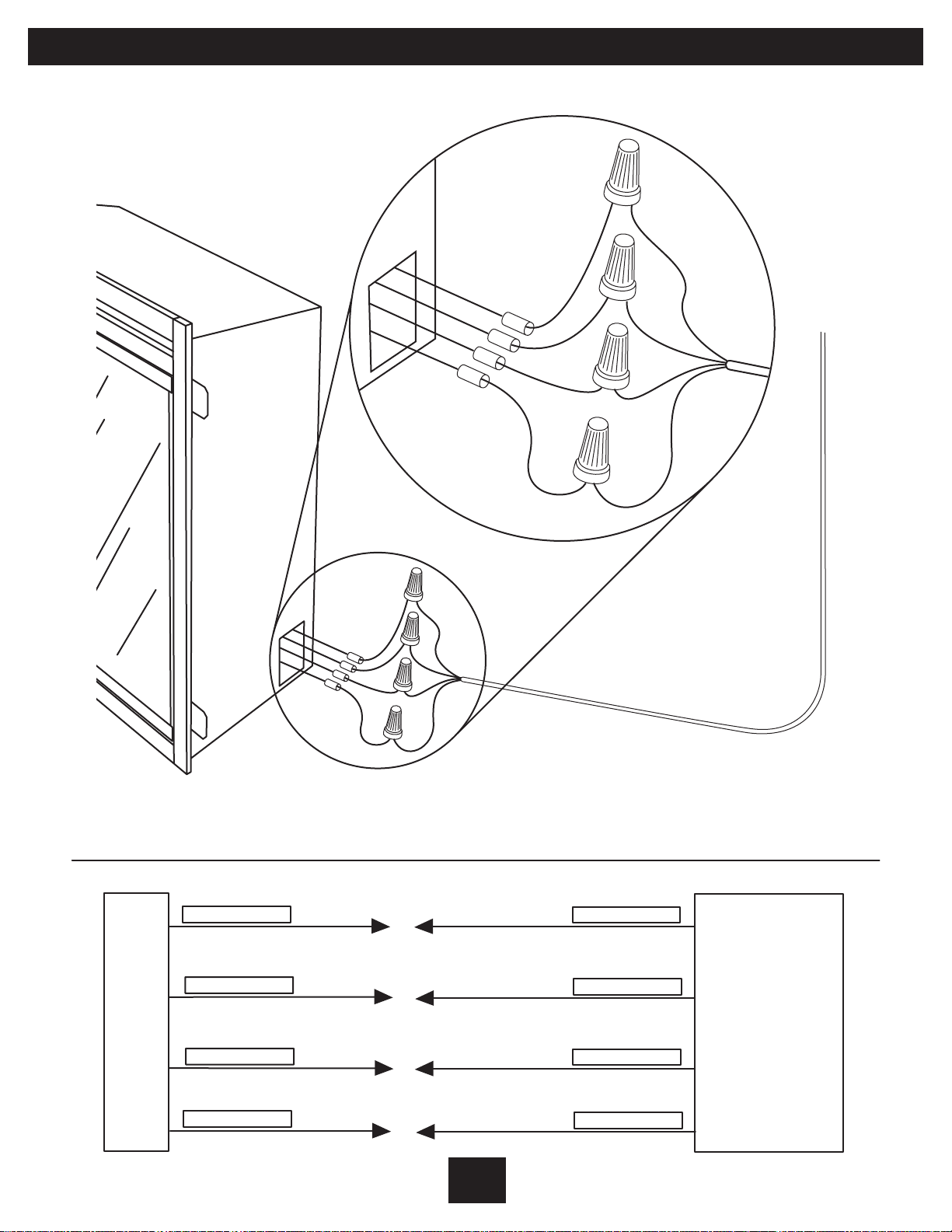
Figure 8: 240V Wire Connection Diagram
N
L2
L1
G
N - WHITE WIRE
L2 - RED WIRE
L1- BLACK WIRE
N
L2
L1
G
N- WHITE WIRE
L2 - RED WIRE
240 VOLT
POWER SUPPLY
BREAKER
L1 - BLACK WIRE
PANEL
FIREPLACE -JUNCTION BOX
G- GREEN WIRE
G - GREEN WIRE
E-10
 Loading...