

Page 1
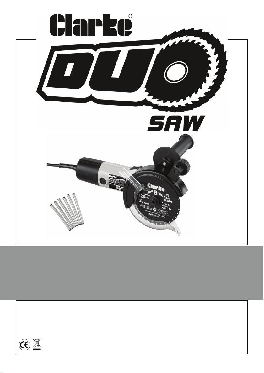
MULTI PURPOSE 5”(125MM) TWIN
BLADE SAW
MODEL NO: TS125
PART NO: 6462047
OPERATION & MAINTENANCE
INSTRUCTIONS
LS1010
Page 2
INTRODUCTION
Thank you for purchasing this CLARKE Multi purpose 5”(125mm) twin blade
Saw.
Before attempting to use this product, please read this manual thoroughly and
follow the instructions carefully. In doing so you will ensure the safety of yourself
and that of others around you, and you can look forward to your purchase
giving you long and satisfactory service.
IMPORTANT
Please read all of the safety and operating instructions carefully before using this
product. Please pay particular attention to all sections of this User Guide that display
warning symbols and notices.
WARNING! This is a Warning symbol. This symbol is used
throughout the user guide whenever there is a risk of personal
injury. Ensure that these warnings are read and understood at all
times.
CAUTION! This is a Caution symbol. This symbol is used throughout the
user guide whenever there is a risk of damaging your product. Ensure
that these cautions are read and understood at all times.
GUARANTEE
This product is guaranteed against faulty manufacture for a period of 12
months from the date of purchase. Please keep your receipt which will be
required as proof of purchase.
This guarantee is invalid if the product is found to have been abused or
tampered with in any way, or not used for the purpose for which it was
intended.
Faulty goods should be returned to their place of purchase, no product can
be returned to us without prior permission.
This guarantee does not effect your statutory rights.
2
Parts & Service: 020 8988 7400 / E-mail: [email protected] or [email protected]
Page 3

TABLE OF CONTENTS
INTRODUCTION .................................................................2
IMPORTANT ........................................................................2
GUARANTEE .......................................................................2
TABLE OF CONTENTS .........................................................3
GENERAL SAFETY RULES ....................................................4
Work Area ........................................................................................ 4
Electrical Safety ............................................................................... 4
Personal Safety ................................................................................ 4
Power Tool Use And Care .............................................................. 5
TWIN SAW SPECIFIC SAFETY INSTRUCTIONS ....................5
SAFETY SYMBOLS ...............................................................6
ELECTRICAL CONNECTIONS .............................................7
OVERVIEW .........................................................................8
IN THE BOX ........................................................................8
BEFORE USE ........................................................................9
Fitting The Side Handle ................................................................... 9
Fitting The Lubricating Sticks .......................................................... 9
USING YOUR DUO SAW ....................................................9
Tips .................................................................................................... 9
Saw Blades ....................................................................................... 10
Blade Guard System ....................................................................... 10
Starting A Cut .................................................................................. 10
CUTTING CROSS SECTIONAL MATERIAL ...........................11
MAINTENANCE ..................................................................12
Changing The Blades ..................................................................... 12
Fitting The Blades ............................................................................ 13
Changing The Carbon Brushes ..................................................... 14
Cleaning .......................................................................................... 14
General Maintenance ................................................................... 14
ENVIRONMENTAL PROTECTION ........................................14
TROUBLESHOOTING ..........................................................15
SPECIFICATIONS ................................................................16
EXPLODED DIAGRAM & PARTS LIST ..................................17
DECLARATION OF CONFORMITY .....................................19
3
Parts & Service: 020 8988 7400 / E-mail: [email protected] or [email protected]
Page 4

GENERAL SAFETY RULES
WORK AREA
1. Keep the work area clean and well lit. Cluttered and dark areas invite accidents.
2. Do not operate power tools in explosive atmospheres, such as in the presence of
flammable liquids, gases or dust. Power tools create sparks which may ignite the
dust or fumes.
3. Keep children and bystanders away while operating a power tool. Distractions can
cause you to lose control.
ELECTRICAL SAFETY
1. Power tool plugs must match the outlet. Never modify the plug in any way. Do not
use adapter plugs with earthed (grounded) power tools. Unmodified plugs and
matching outlets will reduce the risk of electric shock.
2. Do not expose power tools to rain or wet conditions. Water entering a power tool will
increase the risk of electric shock.
3. Do not abuse the cord. Never use the cord for carrying, pulling or unplugging the
power tool. Keep the cord away from heat, oil, sharp edges or moving parts.
Damaged or entangled cords increase the risk of electric shock.
4. When operating a power tool outdoors, use an extension cord suitable for outdoor
use. Use of a cord suitable for outdoor use reduces the risk of electric shock.
5. If operating the power tool in a damp location is unavoidable, use a residual current
device (RCD) protected supply.
PERSONAL SAFETY
1. Stay alert, watch what you are doing and use common sense when operating a
power tool. Do not use a power tool while you are tired or under the influence of
drugs, alcohol or medication. A moment of inattention while operating power tools
may result in personal injury.
2. Use safety equipment. Always wear eye protection. Safety equipment such as dust
mask, non-skid safety shoes, hard hat, or hearing protection used for appropriate
conditions will reduce personal injuries.
3. Avoid accidental starting. Ensure the switch is in the off position before plugging in.
Carrying power tools with your finger on the switch or plugging in power tools that
have the switch on invites accidents.
4. Remove any adjusting key or wrench before turning the power tool on. A wrench or
a key left attached to a rotating part of the power tool may result in personal injury.
5. Do not overreach. Keep proper footing and balance at all times. This enables better
control of the power tool in unexpected situations.
6. Dress properly. Do not wear loose clothing or jewellery. Keep your hair, clothing and
gloves away from moving parts. Loose clothes, jewellery or long hair can be caught
in moving parts.
4
Parts & Service: 020 8988 7400 / E-mail: [email protected] or [email protected]
Page 5

POWER TOOL USE AND CARE
1. Do not force the power tool. Use the correct power tool for your application. The
correct power tool will do the job better and safer at the rate which it was designed.
2. Do not use the power tool if the switch does not turn it on and off. Any power tool that
cannot be controlled with the switch is dangerous and must be repaired.
3. Disconnect the plug from the power source before making any adjustments,
changing accessories, or storing power tools. Such preventive safety measures
reduce the risk of starting the power tool accidentally.
4. Store idle tools out of the reach of children and do not allow persons unfamiliar with
the power tool or these instructions to operate the power tool. Power tools are
dangerous in the hands of untrained users.
5. Maintain power tools. Check for misalignment or binding of moving parts, breakage
of parts and any other condition that may affect the power tools operation. If
damaged, have the power tool repaired before use. Many accidents are caused
by poorly maintained power tools.
6. Keep cutting tools sharp and clean. Well maintained cutting tools with sharp cutting
edges are less likely to bind and are easier to control.
7. Use the power tool and accessories in accordance with these instructions and in the
manner intended, taking into account the working conditions and the work to be
performed. Use of the power tool for operations different from intended could result
in a hazardous situation.
TWIN SAW SPECIFIC SAFETY INSTRUCTIONS
1. Always hold the tool with two hands when in operation.
2. Hold the saw firmly to prevent loss of control.
3. Do not reach underneath the work. The guard cannot protect you from the blade
below the work. Do not attempt to remove cut material when blade is moving.
4. Do not operate saw if the guard does not move freely and close instantly. Never
clamp or tie the guard into the open position.
5. The guard should be retracted manually only for making special cuts such as
“Pocket cuts” and “Compound cuts”.
6. NEVER hold the piece being cut in your hands or across your leg. It is important to
support the work properly and securely to minimize body exposure, blade jamming,
or loss of control.
7. Do not remove saw from work during a cut while the blade is moving. Do not force
tool. Stay alert, exercise control.
8. The Duo Saw can saw lumber with nails, but it is advisable to remove all nails from
lumber before sawing, as the life of the blade may be shortened.
5
Parts & Service: 020 8988 7400 / E-mail: [email protected] or [email protected]
Page 6
SAFETY SYMBOLS
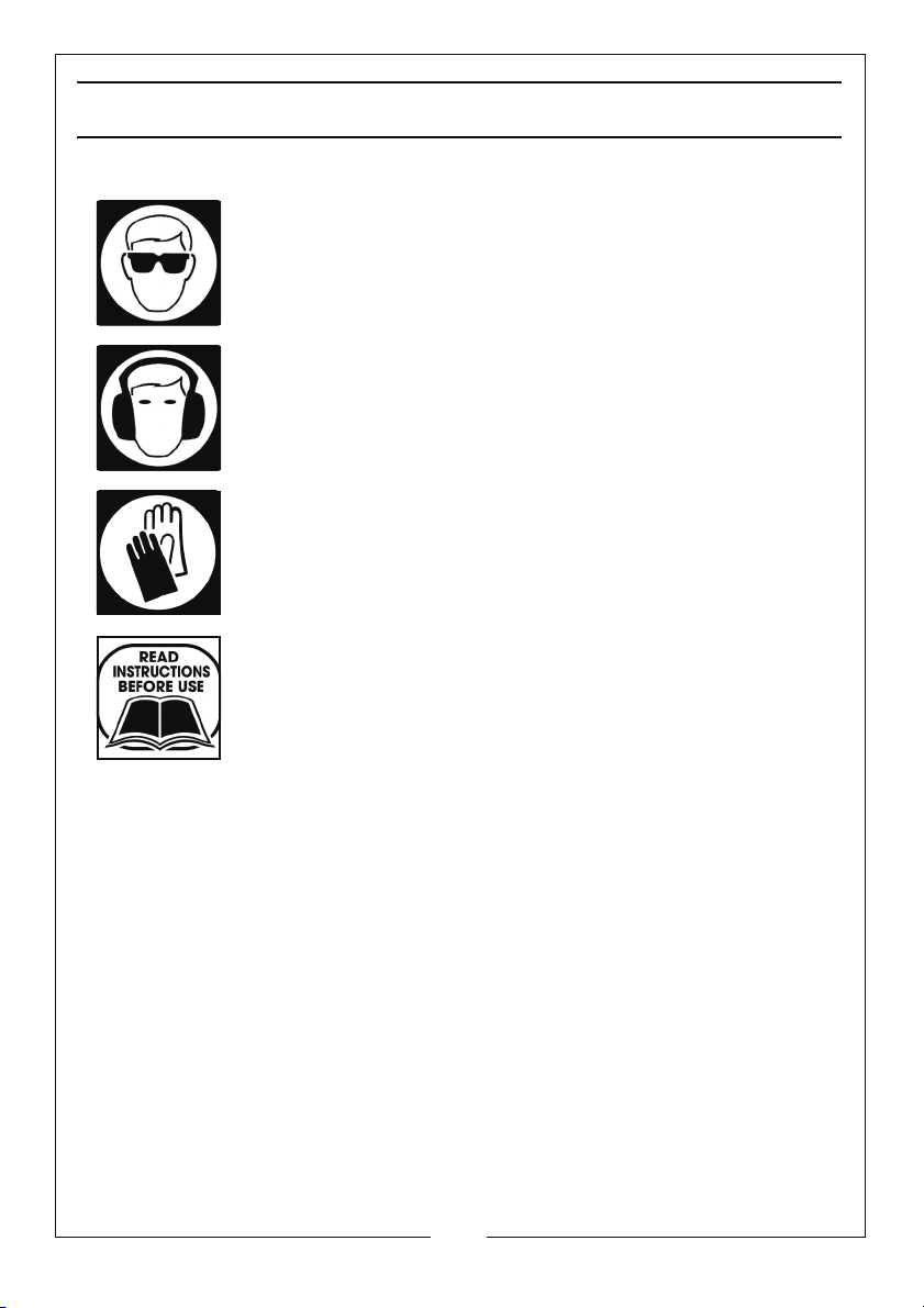
Wear eye protection
Wear ear defenders
Wear protective gloves
Read instruction manual before use
6
Parts & Service: 020 8988 7400 / E-mail: [email protected] or [email protected]
Page 7
ELECTRICAL CONNECTIONS
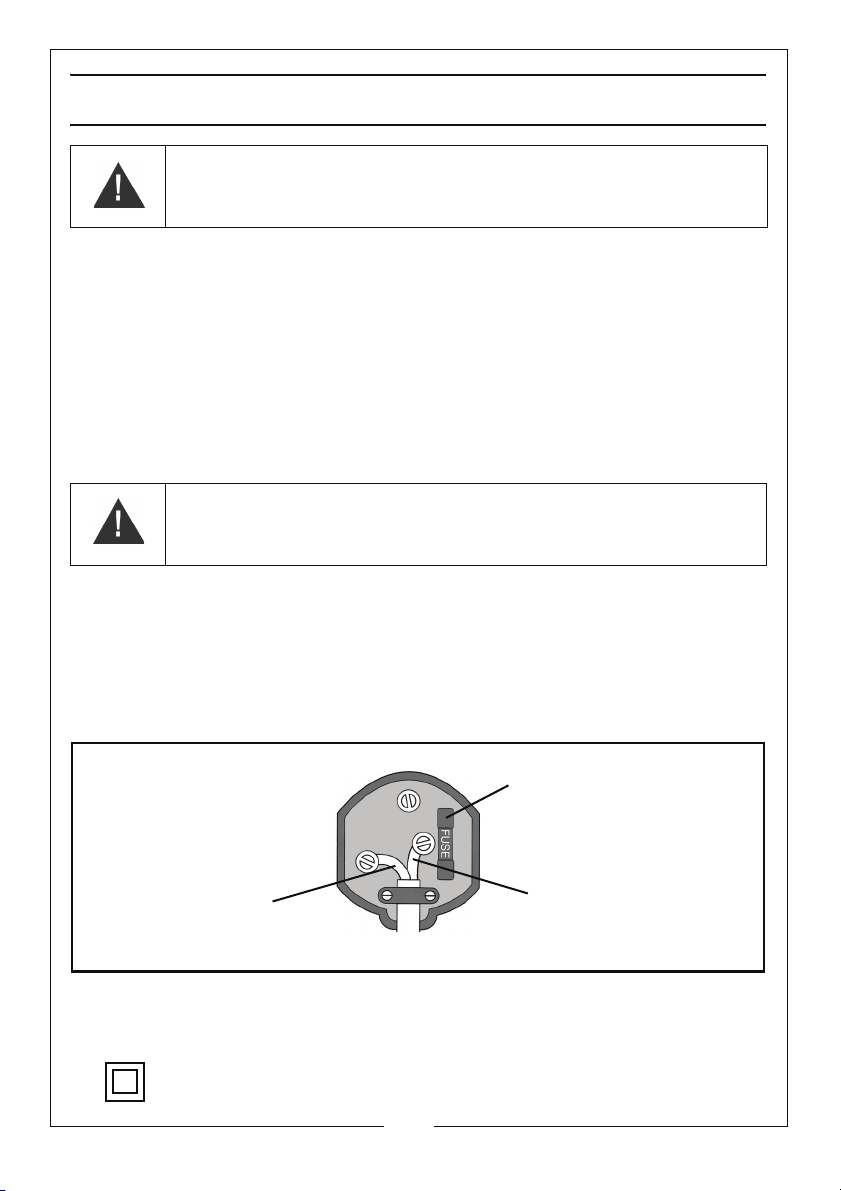
Plug must be BS1363/A approved.
Always fit a 13 Amp fuse.
Ensure that the outer sheath of the cable is firmly held by the clamp
Neutral
(Blue)
Live
(Brown)
WARNING! Read these electrical safety instructions thoroughly
before connecting the product to the mains supply.
Before switching the product on, make sure that the voltage of your electricity supply is
the same as that indicated on the rating plate. This product is designed to operate on
230VAC 50Hz. Connecting it to any other power source may cause damage.
This product may be fitted with a non-rewireable plug. If it is necessary to change the
fuse in the plug, the fuse cover must be refitted. If the fuse cover becomes lost or
damaged, the plug must not be used until a suitable replacement is obtained.
If the plug has to be changed because it is not suitable for your socket, or due to
damage, it should be cut off and a replacement fitted, following the wiring instructions
shown below. The old plug must be disposed of safely, as insertion into a mains socket
could cause an electrical hazard.
WARNING! The wires in the power cable of this product are
coloured in accordance with the following code:
Blue = Neutral Brown = Live
If the colours of the wires in the power cable of this product do not correspond with the
markings on the terminals of your plug, proceed as follows.
• The wire which is coloured Blue must be connected to the terminal which is
marked N or coloured Black.
• The wire which is coloured Brown must be connected to the terminal which is
marked L or coloured Red.
We strongly recommend that this machine is connected to the mains supply via a
Residual Current Device (RCD)
If in any doubt, consult a qualified electrician. DO NOT attempt any repairs yourself.
This symbol indicates that this is a Class II product, and does not require an
earth connection.
Parts & Service: 020 8988 7400 / E-mail: [email protected] or [email protected]
7
Page 8
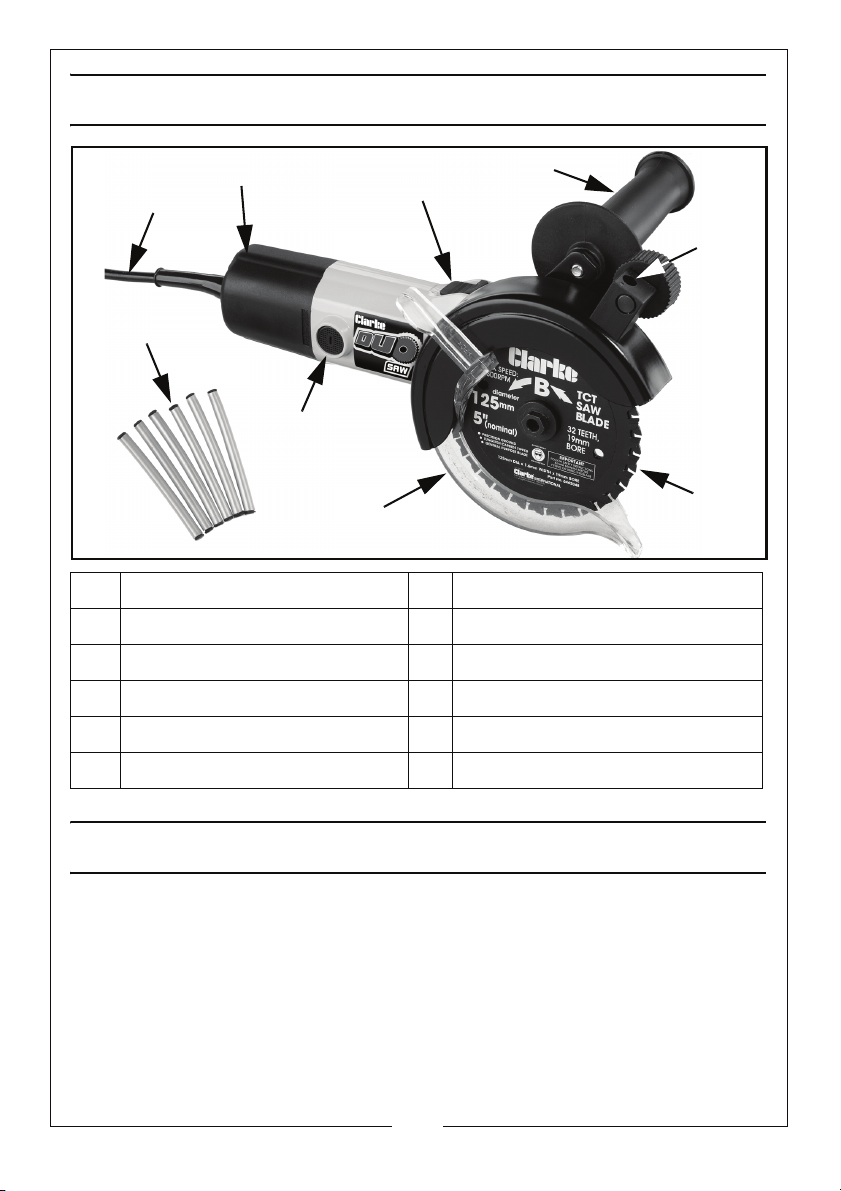
OVERVIEW
1
2
3
4
5
6
7
8
9
NO DESCRIPTION NO DESCRIPTION
1 Mains Lead 6 Blade Guard
2 ON/OFF Switch 7 Brush Cover Screw
3 Side Handle 8 Lubrication Sticks
4 Lubrication Stick Holder 9 Overload Cut Out Switch
5 Blade x 2
IN THE BOX
The following should be supplied. If anything is missing contact your dealer
1 X 5”(125mm) Twin Blade Saw 1 X Pack Of 6 Lubrication Sticks
1 X Pair Of CTC 125 'Universal Blades' 1 X Blow Moulded Case
1 X Box Wrench & Locking Pin 1 X Set Of Spare Carbon Brushes
1 X Auxiliary Handle 1 X User Manual
Parts & Service: 020 8988 7400 / E-mail: [email protected] or [email protected]
8
Page 9
BEFORE USE
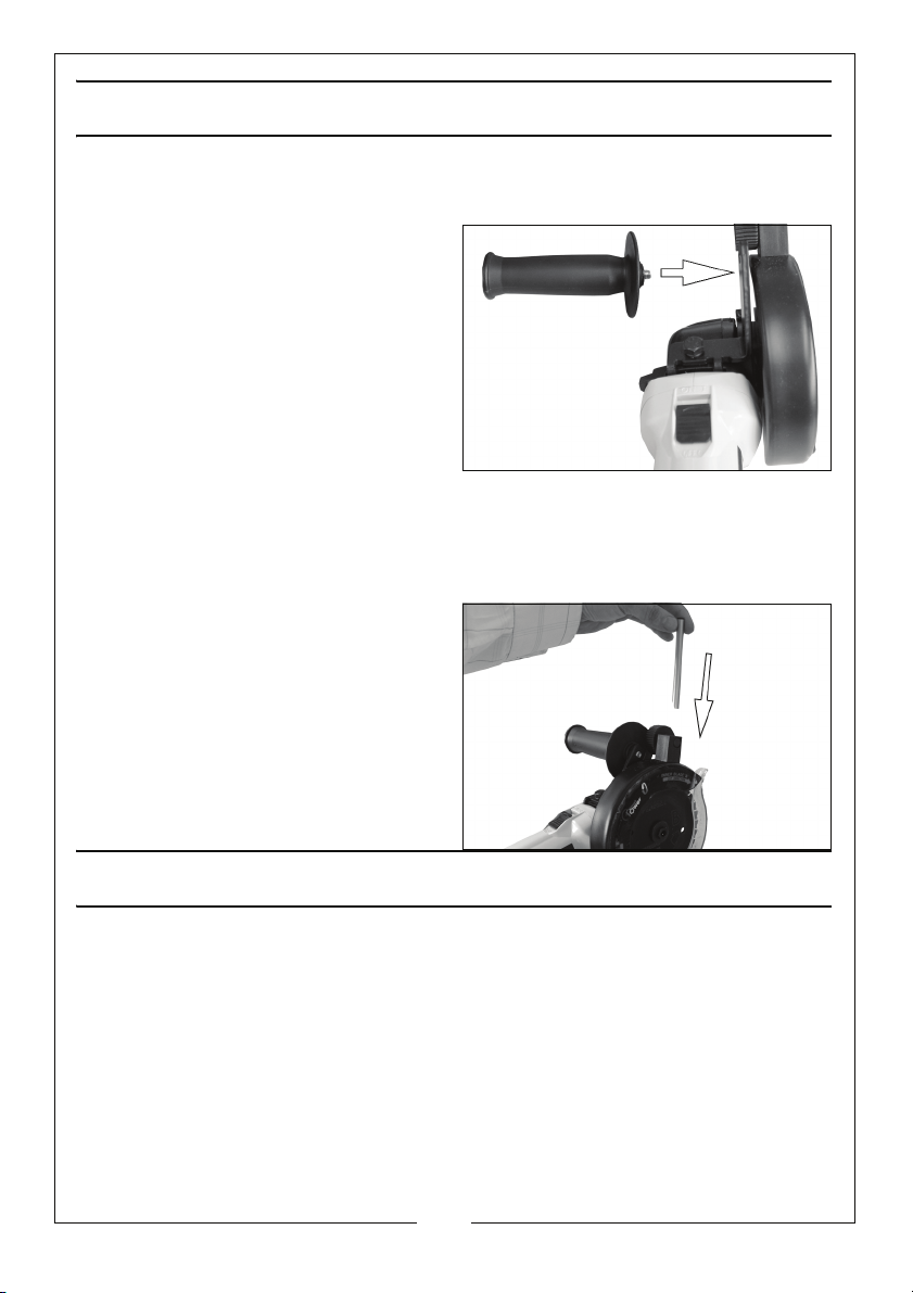
FITTING THE SIDE HANDLE
1. Fit the side handle to the Duo Saw
as shown.
FITTING THE LUBRICATING STICKS
When cutting Aluminium, Copper, Stainless Steel & Cast Iron you should use the
lubricating sticks to prevent the blades from overheating.
1. Slide the lubricating stick into the
lubrication stick holder as shown.
2. To lower the stick rotate the small
dial next to the lubrication stick
holder towards you.
3. Replacment lubricating sticks are
available from your CLARKE
dealer, Part number 6462049.
USING YOUR DUO SAW
TIPS
• ALWAYS support the workpiece near the cut.
• ALWAYS clamp the workpiece securely so it will not move during the
cut. Before starting a cut, draw a guideline along the desired line of
cut.
• ALWAYS keep the mains cord away from the cutting area.
9
Parts & Service: 020 8988 7400 / E-mail: [email protected] or [email protected]
Page 10
SAW BLADES
WARNING: THIS DUO SAW USES SPECIALLY DESIGNED BLADES AND NO
OTHER TYPE OF BLADES SHOULD EVER BE USED. OTHER BLADES WILL NOT
OPERATE SAFELY IN THIS SAW AND COULD RESULT IN SERIOUS PERSONAL
INJURY.
Even the best saw blades will not cut efficiently if they are not kept clean,
sharp and properly set. Gum and wood pitch hardened on your blade will
slow your saw down. Use gum and pitch remover, or hot water to remove
these accumulations.
BLADE GUARD SYSTEM
The blade guard, attached to your saw should never be altered for any
reason. If it becomes damaged or begins to return slowly or sluggishly, DO NOT
operate your saw until it has been repaired or replaced.
ALWAYS keep your hands and fingers away from the cutting area. Any part of
your body coming in contact with the moving blade will result in serious injury.
STARTING A CUT
WARNING: USING THE SAW WITH A DAMAGED CORD COULD RESULT IN
SERIOUS INJURY OR DEATH. IF THE CORD HAS BEEN DAMAGED, HAVE IT
REPLACED BEFORE USING THE SAW.
WARNING: NEVER USE THE SAW WHEN THE GUARD IS NOT OPERATING
PROPERLY. THE GUARD SHOULD BE CHECKED FOR CORRECT OPERATION
BEFORE EACH USE.
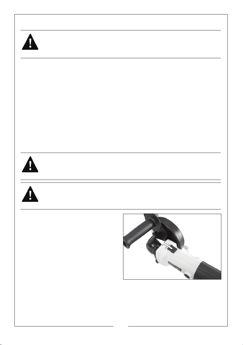
1. Slide the on/off switch forwards to
start the saw.
• To prevent kickback, allow the
blades to reach full speed
before you begin to cut into
the workpiece.
• Make sure both blades enter
into the workpiece at the same
time. Entering with only one
blade will cause unexpected
kickback.
2. When making a cut, use steady, even pressure.
• Forcing the saw causes rough cuts and could shorten the life of the
saw or cause kickback.
10
Parts & Service: 020 8988 7400 / E-mail: [email protected] or [email protected]
Page 11
CUTTING CROSS SECTIONAL MATERIAL
The life span of the blade and the quality of the cutting edge is dependent
on vibrations being kept to a minimum. For this reason the material must
always be clamped in place before work proceeds.
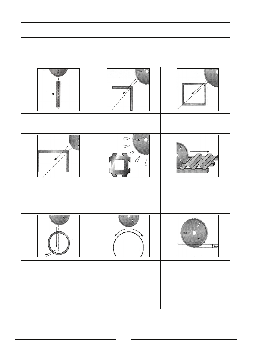
Flat bar iron
The blade is fed at an angle of
90° to the work surface
U-section
The blade is fed from corner to
corner.
Pipes
The blade is fed through the
object until it reaches the lower
edge, angled as it goes so that
the blade hits the material at an
angle of 90°.
Corner piece
The blade is fed diagonally
through the work surface.
Aluminium/copper
The machine must always be
equipped with the lubricating
device, to be used when
cutting all kinds of aluminium
and copper.
Spiral tube and longitudinal
cutting
Feed the blade through the
material, so that the blade only
protrudes through approx. 10
mm, do not drive it as far as the
blade's entire cutting edge.
Then start to feed the blade
forwards or backwards.
Rectangular pipe
The blade is fed from corner to
corner.
Shaped plate
The plate must always rest on
three mounts, with one on either
side of the cut.
Thin plate
Only feed the blade down
approx. 10 mm. Then start
cutting.
The Blade Cover Guard is fixed to protect the operator from chips. When the
blades rotates, the chip flow comes out in both directions, which must be
observed.
11
Parts & Service: 020 8988 7400 / E-mail: [email protected] or [email protected]
Page 12
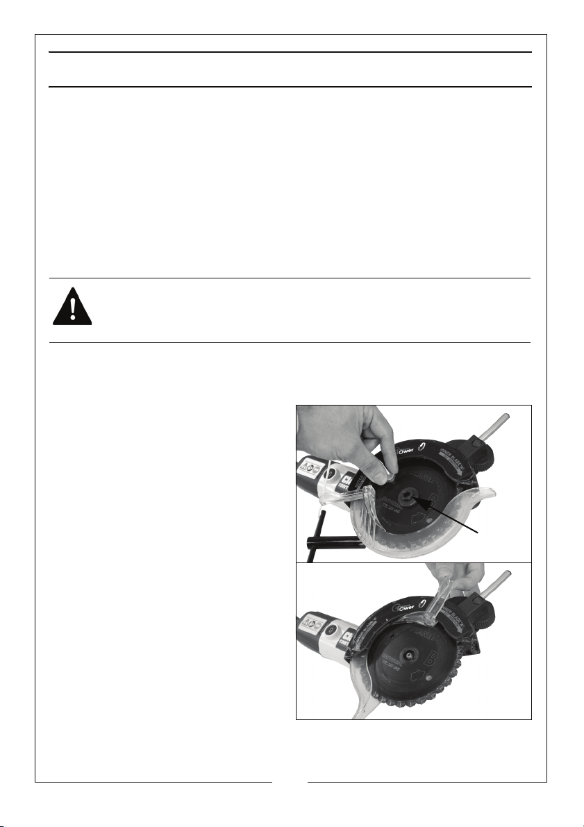
MAINTENANCE
Lock
Nut
CHANGING THE BLADES
• This Duo Saw uses specially designed blades available from your
Clarke dealer: no other types of blade should ever be used. Other
types of blades will not operate safely in this saw & could result in
serious personal injury.
• The side of the blades cannot be used for cutting. Therefore, in
horizontal cuts, make sure saw is not resting on lower blade and
wedge the workpiece to prevent unexpected trapping of the
blade.
WARNING: MAKE SURE THAT THE DUO SAW IS SWITCHED OFF AND
UNPLUGGED FROM THE MAINS SUPPLY BEFORE FITTING OR REMOVING
ANY BLADES.
REMOVING THE BLADES
1. Use the wrench supplied to line up the holes in the blade.
2. Insert the pin into the holes to lock
the blades in position.
3. Use the wrench to remove the
lock nut (turn anticlockwise to
release).
4. Slide the guard back and hold in
position.
5. Remove blade ‘B’.
6. Remove blade ‘A’.
• A pair of replacment blades
are available from your CLARKE
dealer, Part number 6462048.
Parts & Service: 020 8988 7400 / E-mail: [email protected] or [email protected]
12
Page 13
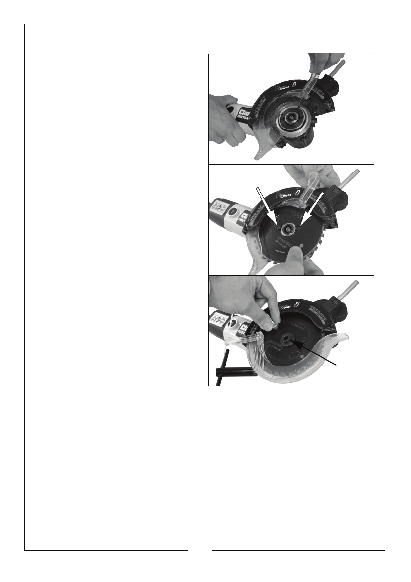
FITTING THE BLADES
Lock
Nut
1. Slide the guard back and hold in
position.
2. Place blade ‘A’ onto the spindle
with the label facing outwards.
• Align the pins on the drive
flange with the holes on the
blade.
3. Place blade ‘B’ onto the spindle
with the label facing outwards.
4. Place the lock nut onto the
spindle. DO NOT tighten yet.
5. Turn the blades to align the two
holes on the blades and insert the
locking pin.
6. Tighten the locking nut clockwise
to secure the blades then remove
the locking pin.
Parts & Service: 020 8988 7400 / E-mail: [email protected] or [email protected]
13
Page 14
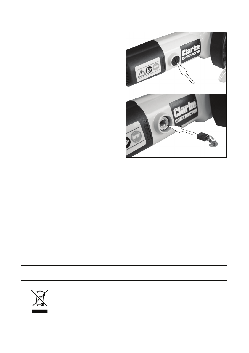
CHANGING THE CARBON BRUSHES
1. Remove the screw holding the
brush cover in place.
2. Slide out the carbon brush.
3. Replace with the new brush
supplied.
4. Repeat on the other side of the
body.
NOTE: Both brushes must be
replaced at the same time.
CLEANING
• To maintain the best possible performance from your Duo Saw, it
must be kept clean.
• To reduce fire hazard, keep the cooling vents free of debris.
• Clean the area around the spindle and keep the locking nut clean.
GENERAL MAINTENANCE
• Check the secondary handle and the guard for damage.
• Always have any damaged, or worn parts repaired, or replaced.
• Always have your Duo Saw inspected and maintained by qualified
service personnel. Do not attempt to repair the Duo Saw unless you
are qualified to do so.
ENVIRONMENTAL PROTECTION
Recycle unwanted materials instead of disposing of them as
waste. All tools, accessories and packaging should be sorted,
taken to a recycling centre and disposed of in a manner which is
compatible with the environment.
14
Parts & Service: 020 8988 7400 / E-mail: [email protected] or [email protected]
Page 15
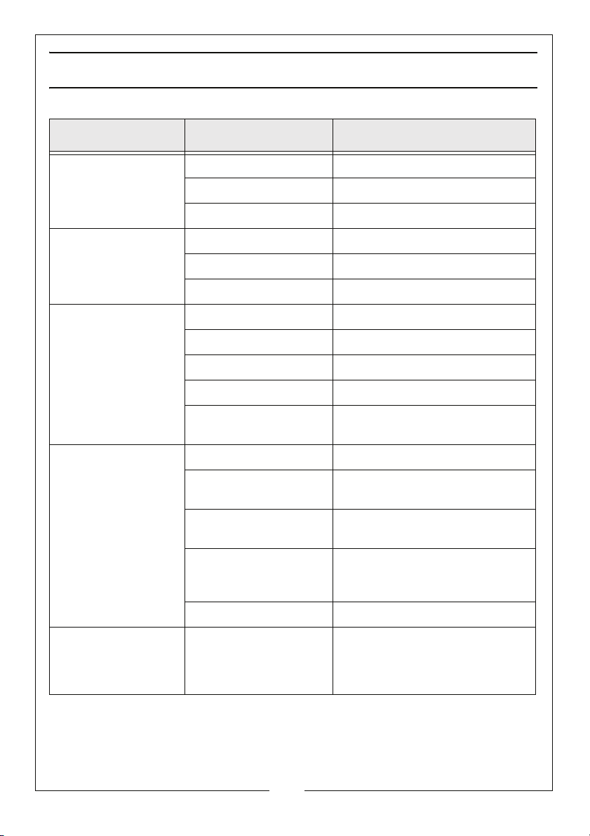
TROUBLESHOOTING
PROBLEM CAUSE SOLUTION
Unusually large
amount of sparks.
A lot of wear in
sections.
Blades are breaking. Damaged teeth. Replace blades.
Possible causes of
broken teeth.
Damaged teeth. Replace blades
Feed speed is too slow. Increase feed speed
Blunt teeth. Mount new set of cutter blades
Feed speed is too fast. Reduce the feed speed.
Damaged teeth. Replace blades
Blunt teeth. Replace blades.
Feed speed is too fast. Reduce the feed speed.
Blunt teeth. Replace blades.
Blades have buckled. Replace blades.
Blades have burned
out.
Feed speed is too fast. Replace blades.
The Surface being cut is
too hard.
The teeth have been
damaged by impact.
Blade were not installed
correctly.
Replace blades.
Replace blades.
Replace blades.
Replace blades and follow the
proper blade installation
instructions.
Blades are burned out. Replace blades.
Duo Saw cuts out
during use.
Overload cut out has
tripped.
Stop work and remove the blade
from the workpiece, Reset the cut
out by pushing it back into the
saw.
15
Parts & Service: 020 8988 7400 / E-mail: [email protected] or [email protected]
Page 16
SPECIFICATIONS
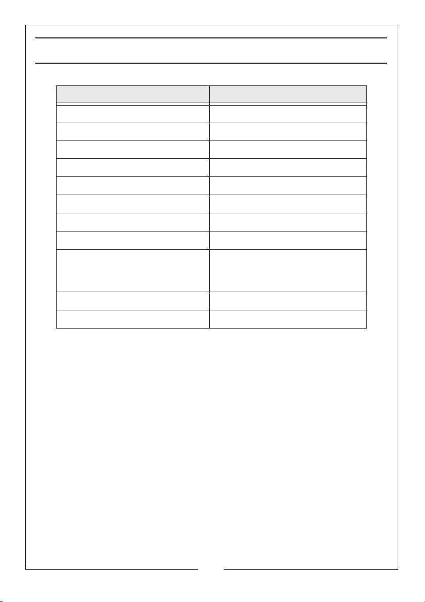
Model Number TS125
Rated Voltage 230 V @ 50Hz
Input Power 650 W
No Load Speed 5500 rpm
Blade Diameter 5 inches (125 mm)
Maximum Depth of Cut 28 mm
Sound Pressure Level (L
Guaranteed Sound Power (L
Vibration Levels
pA dB) 90 dB(A)
wA dB) 101 dB(A)
1.559 m/s
1.383 m/s
K = 1.5 m/s
2
at the Main Handle
2
at the Auxiliary Handle
2
Dimensions (L x W x H) 345 x 197 x 192 mm
Weight 3.31 Kg
16
Parts & Service: 020 8988 7400 / E-mail: [email protected] or [email protected]
Page 17
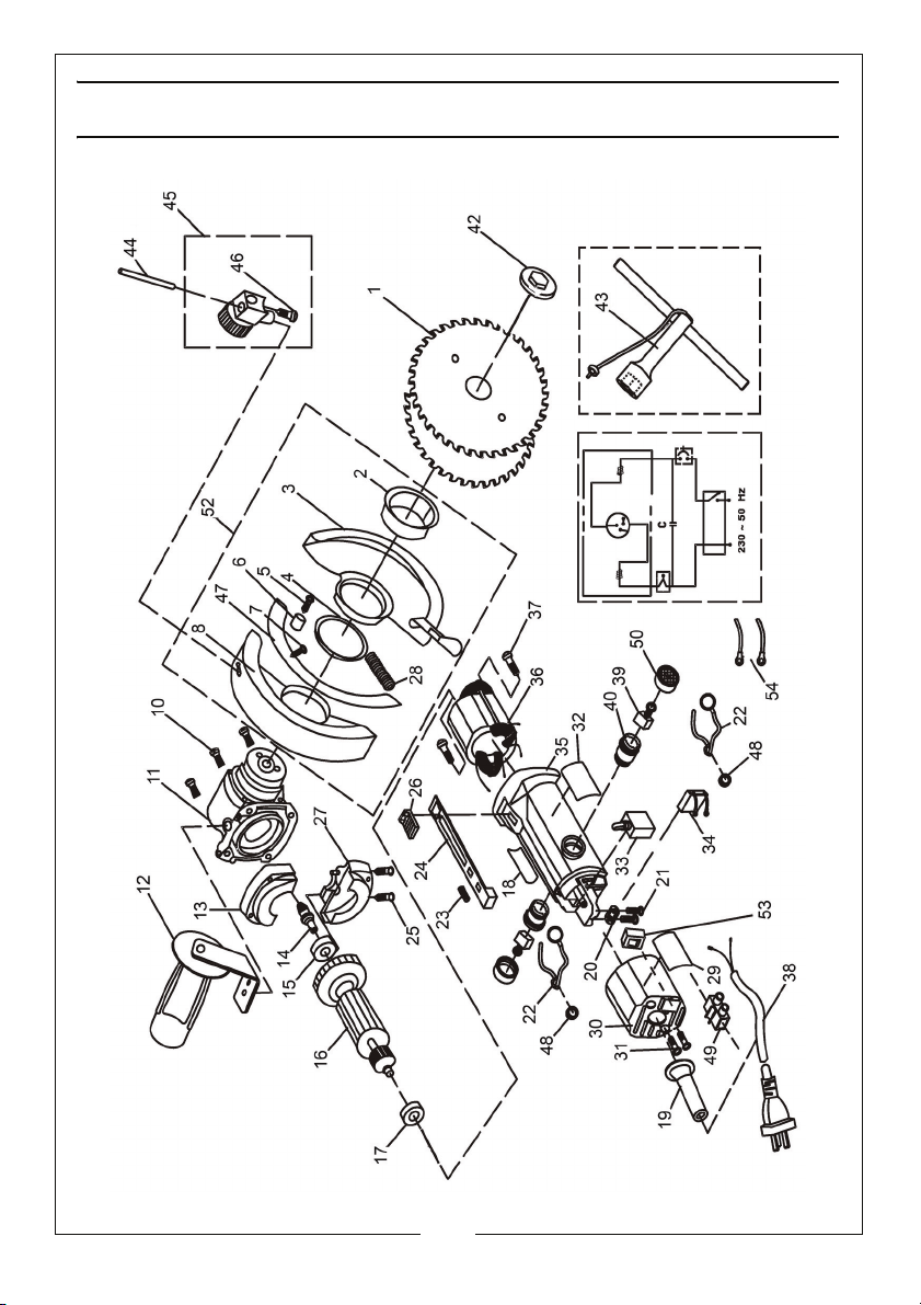
EXPLODED DIAGRAM & PARTS LIST
17
Parts & Service: 020 8988 7400 / E-mail: [email protected] or [email protected]
Page 18
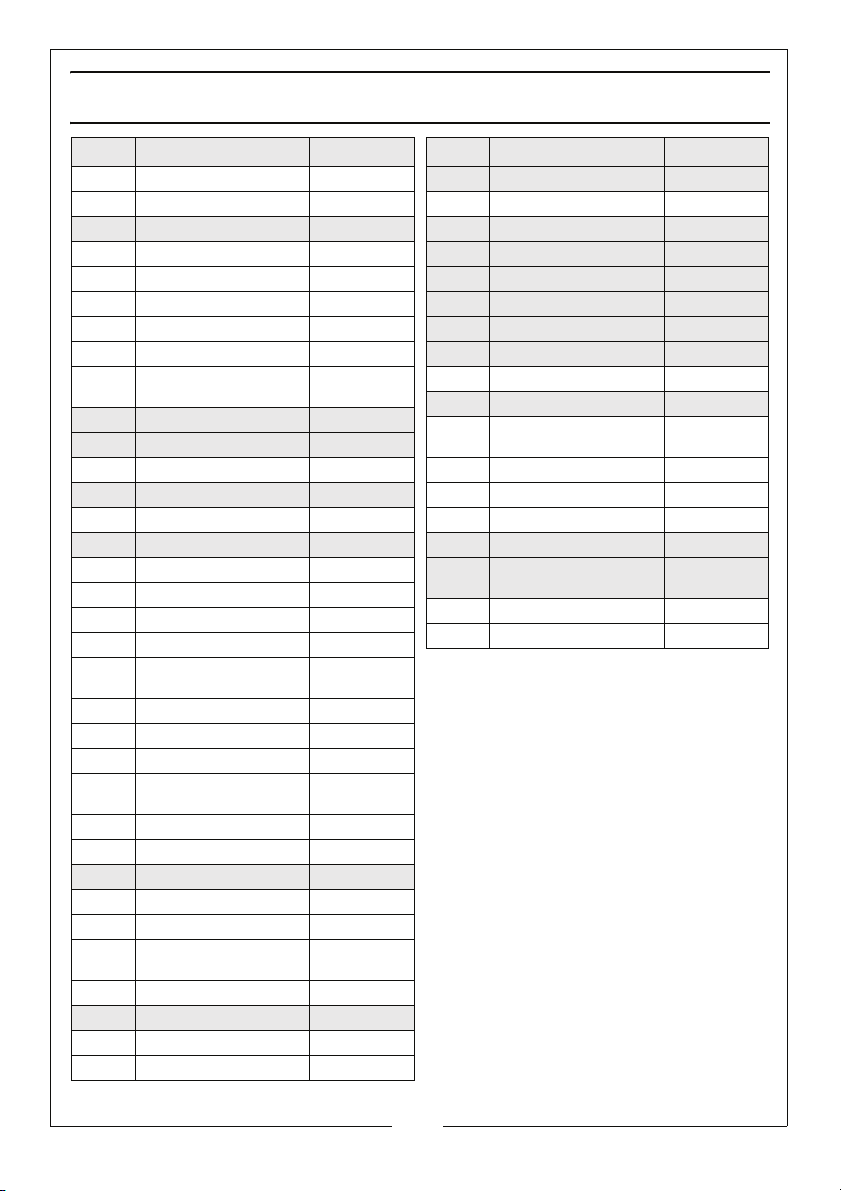
EXPLODED DIAGRAM & PARTS LIST
No Description Part No
1 Blade HTTS125001
2 Guard Plate HTTS125002
3 Guard HTTS125003
4 Guard Washer HTTS125004
5 Screw M4 X 14 HTTS125005
6 Rubber Pin HTTS125006
7 Screw SA M4x19 HTTS125007
8 Guard HTTS125008
10 Self Tapping Screw ST
11 Gear Box Assy HTTS125011
12 Side Handle HTTS125012
13 Cover HTTS125013
14 Pinion HTTS125014
15 Bearing HTTS125015
16 Armature HTTS125016
17 Bearing HTTS125017
18 Brand Label HTTS125018
19 Cord Protector HTTS125019
20 Cord Clamp HTTS125020
21 Self Tapping Screw ST
22 Lead Wire HTTS125022
23 Spring HTTS125023
24 Switch Lever HTTS125024
25 Self Tapping Screw ST
26 Switch HTTS125026
27 Lower Cover HTTS125027
28 Spring HTTS125028
29 Safety Label HTTS125029
30 Back Cover HTTS125030
31 Self Tapping Screw ST
32 Name Plate HTTS125032
33 Switch HTTS125033
34 Capacitor HTTS125034
35 Housing HTTS125035
4.2x35
4.2x12
4.2x20
4.2x16
HTTS125010
HTTS125021
HTTS125025
HTTS125031
No Description Part No
36 Stator HTTS125036
37 Tapping Screw ST 4.2x14 HTTS125037
38 Cord and Plug HTTS125038
39 Carbon Brush HTTS125039
40 Brush Holder HTTS125040
41 Arbor Adaptor HTTS125041
42 Lock Nut HTTS125042
43 Wrench with Pin HTTS125043
44 Lubricating Stick HTTS125044
45 Lubricating unit HTTS125045
46 Self Tapping Screw ST
4.8x10
47 Rotational Label HTTS125047
48 Inductor Coil HTTS125048
49 Connector HTTS125049
50 Carbon Brush Cover HTTS125050
52 Guard Assembly (parts
2, 3, 4, 8, and 28)
53 Overload Protector HTTS125053
54 Lead Wire HTTS125054
HTTS125046
HTTS125052
Only highlighted parts are replaceable.
18
Parts & Service: 020 8988 7400 / E-mail: [email protected] or [email protected]
Page 19
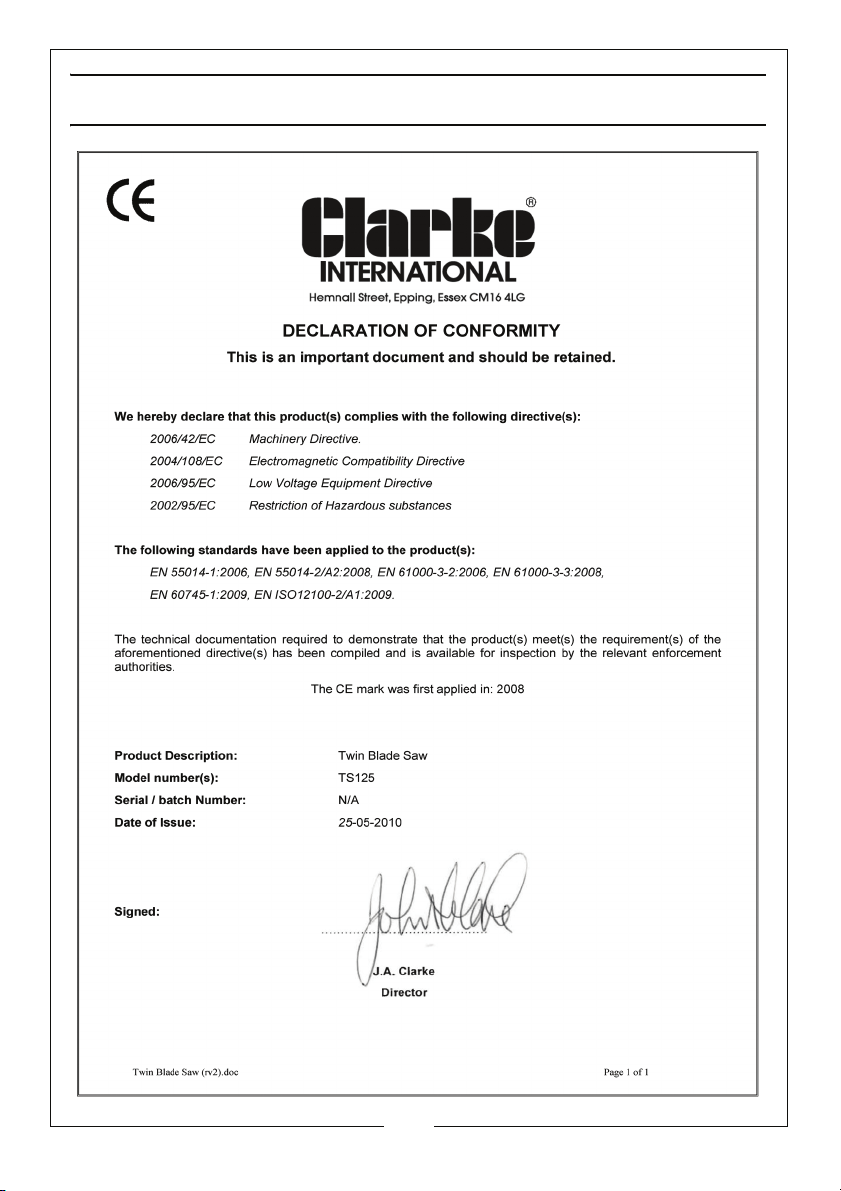
DECLARATION OF CONFORMITY
19
Parts & Service: 020 8988 7400 / E-mail: [email protected] or [email protected]
Page 20

 Loading...