

Page 1
For sparts and servicing, please contact your nearest dealer or MACHINE MART on one of the following numbers
AIR COMPRESSOR
TIGER 5/12 & 5/12K
OPERATING & MAINTENANCE
INSTRUCTIONS
0202
Page 2
Please note that the details and specifications contained herein, are correct at the time of going to print. However,
TEL- 0115 956 1809 Fax:- 0115 956 2910
AIRMASTER reserve the right to change specifications at any time without prior notice.
TEL:- 0115 956 1805 Fax:- 0115 979 9929
For Spare Parts and Servicing, please contact your nearest dealer, or
Part Nos. 5/12 ....................... 000114060
Machine Mart on one of the following numbers.
PARTS & SERVICE CONTACTS
SERVICE
PARTS
5/12K .................... 18kg
5/12K .................... 000114040
Air Receiver ........................................... 12 litre
Weight (Packed) 5/12 ....................... 16.7kg:
Max. Air Pressure .................................. 115 lbf/in
Max. Air Pressure .................................. 8 bar
Air Displacement .................................. 4 cuft/min
2
Electrical Supply ................................... 230 V, 1 Phase 50Hz
Motor Rating .......................................... 0.7 HP
SPECIFICATIONS
15
9/10 Outlet Tap compl. ZT500410
11 Power Cable N/A
12 Reducer valve ZT580412
- Rubber Foot ZT512315
- Red Regulator Cap ZT580420
4A Pressure Switch Cover
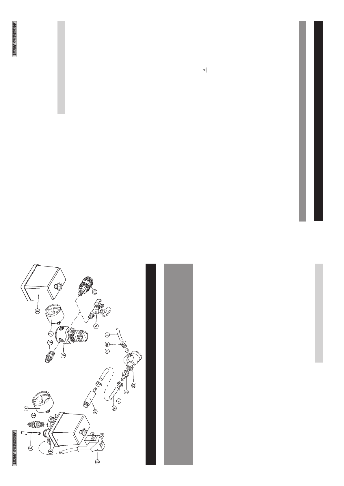
4 Pressure Switch Assy. ZT580404
5 Nipple ZT580405
6 Pressure Regulator ZT583406
7 Pressure Gauge 40mm
ZSD996K23C
- Outlet Elbow ZT500317
ZA9614011
17 Olive ZT580417
18 Hose Connector ZT580418
19 Bleed Pipe ZT500403
16 Outlet Conn. ZT580416
1 Pressure Gauge 50mm ZSD996A24D
2 Safety Valve ZT580402
3 Tube ZT500403
13 Nut & Tail ZT580413
14 Worm Drive Clip ZT580414
15 Red Delivery Pipe ZT580415
No. Description Part No.
AUXILLIARIES (See Page 13)
No. Description Part No.
17 Piston ZT800017
18 Gudgeon Pin ZT800018
19 Con-Rod ZT580019
20 Crankshaft Nut ZT580020
21 Piston Ring Set ZT800021
22 Circlip ZT580022
49 End Housing ZT800049
50 Screw ZT580050
52 Mounting Plate ZT580052
54 Bolt ZT800054
56 Cover ZT580056
- Receiver Drain Cock
14 Cyl. Hd. Screw ZT580014
15 Washer ZT580015
16 Sealing Ring ZT580016
39 Rubber Foot ZT580039
47 Stator ZT800047
48 Washer ZT580048
11 Upper Head Gasket ZT580011
12 Lower Head Gasket ZT800012
13 End Cover ZT580013
36 Bolt ZT580036
37 Washer ZT580037
38 Bearing ZT800038
10 Air Filter ZT580010
8 Screw ZT580008
9 Filter Housing ZT580009
32 Nut ZT580032
33 Capacitor ZT800033
34 Fan ZT580034
5 Crankcase ZT800005
6 Housing ZT800006
7 Valve Assembly ZT800007
27 Bearing ZT800027
29 Circlip ZT580029
31 Flange Seal ZT580031
2 Screw ZT580002
3 Cylinder Head ZT580003
4 Insert ZT580004
24 Crankshaft ZT580024
25 Piston Assyw/17-19,&22 ZT800025
26 Rotor ZT800026
No. Description Part No.
1 Oil Filler Cap ZT580001
No. Description Part No.
23 Valve Strip ZT800117
PARTS LIST
FN022003000
Page 3
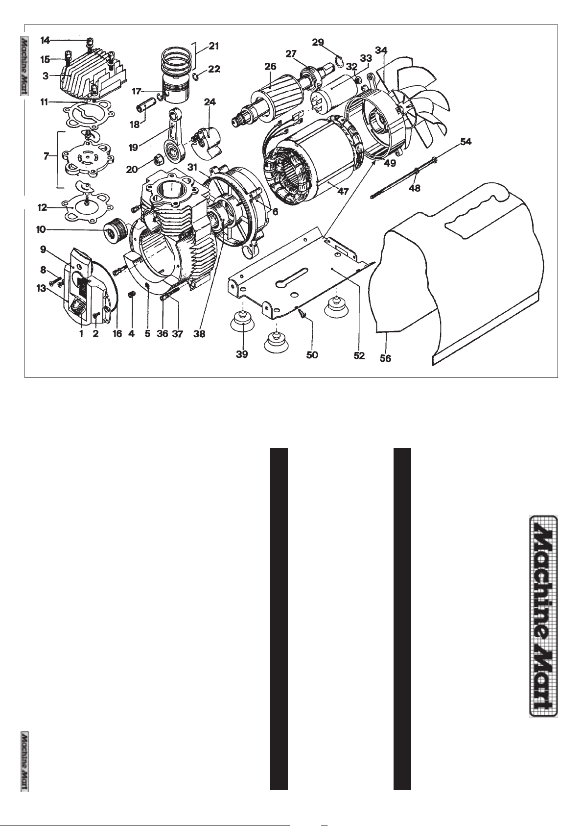
PARTS DIAGRAM
14
This product is guaranteed against faulty manufacture for a period of 12 months
from the date of purchase. Please keep your receipt as proof of purchase. This
guarantee is invalid if the product is found to have been abused or tampered with
in any way, or not used for the purpose for which it was intended.
Faulty goods should be returned to their place of purchase, no product can be
returned to us without prior permission.
This guarantee does not effect your statutory rights.
CONTENTS Page
Specifications ................................................................................... 3
Electrical Connections .................................................................... 4
Safety Precautions ........................................................................... 5
Diagram and Operating Instructions ............................................. 6
Shutting Down the Compressor ...................................................... 7
Routine Maintenance ..................................................................... 7
Trouble Shooting .............................................................................. 9
Accessories ....................................................................................... 9
General Guidance on the use of Accessories ........................... 10
Parts List and Diagrams .......................................................... 13 - 15
Spray gun maintenance.......................... 13
3
Paint Spraying Hints - General preparation ................................ 11
Handling the gun ...................................... 12
GUARANTEE
look forward to the TIGER Air Compressor giving you long and satisfactory service.
Thank you for purchasing this TIGER 5/12 Air Compressor. Complete with a 12 litre
air receiver, this machine is designed to deliver air at up to 115 lbf/in
2
, ideal for most
DIY applications.
Please read this booklet thoroughly and follow the instructions carefully, in doing so
you will ensure the safety of yourself and that of others around you, and you can
Page 4
The fuse in the plug for this appliance must be rated at 13 amps
As the colours of the flexible cord of this appliance may not correspond with the
If this appliance is fitted with a plug which is moulded onto the electric cable (i.e.
non-rewirable) please note:
1. The plug must be thrown away if it is cut from the electric cable. There is a
2. Never use the plug without the fuse cover fitted.
3. Should you wish to replace a detachable fuse carrier, ensure that the correct
4. Replacement fuse covers can be obtained from your local dealer or most
5. The fuse in the plug must be replaced with one of the same rating (13 amps)
We recommend that this machine is connected to the mains supply through a
Residual Current Device (RCD).
If in doubt, consult a qualified electrician. Do not attempt any electrical repairs
yourself.
coloured markings identifying terminals in your plug proceed as follows:
following code:
This product is provided with a standard 13 amp, 230 volt (50Hz), BS 1363 plug, for
connection to a standard, domestic electrical supply. Should the plug need
changing at any time, ensure that a plug of identical specification is used.
IMPORTANT: The wires in the mains lead are coloured in accordance with the
FUSE RATING
4
and this replacement must be ASTA approved to BS1362.
replacement is used (as indicated by marking or colour code).
electrical stockists.
danger of electric shock if it is subsequently inserted into a socket outlet.
Connect BLUE cord to terminal marked with a letter “N” or coloured BLACK.
Green & Yellow .................... Earth
Brown .................... Live
Blue .................... Neutral
Connect GREEN & YELLOW cord to plug terminal marked with a letter “E” or
Earth symbol “ ” or coloured GREEN or GREEN & YELLOW.
Connect BROWN cord to terminal marked with a letter “L” or coloured RED.
ELECTRICAL CONNECTIONS
WARNING: THIS MACHINE MUST BE EARTHED.
1. Immerse only the front end of the gun until solvent just covers the fluid connection.
2. Use a bristle brush and solvent to wash off accumulated paint.
4. Wipe down the outside of the gun with solvent dampened rag.
Coat the fluid control spring with vaseline.
6. Caution: Never use lubricants containing silicone, this may cause finish defects.
5. Lubricate gun daily. Use a light machine oil on:
3. Do not submerge the entire spray gun in solvent because:
UNDER PRESSURE. ALWAYS MAKE CERTAIN THAT ALL AIR HAS BEEN EXHAUSTED.
NEVER UNSCREW A COMPRESSOR CONNECTION WHILST THE MACHINE IN
d. trigger pivot point.
a. fluid needle packing.
b. air valve packing.
c. fan control packing.
SPARE PARTS
c. residue from dirty solvent may clog the narrow air passages in the gun.
faster wear.
a. the lubricant in the leather packings will dissolve and the packings will
dry out.
b. the lubricant at wear surfaces will dissolve causing harder operation and
4. SPRAY GUN MAINTENANCE
WARNING
13
Page 5
For a professional looking finish paint must be thinned. If the manufacturers
recommendations on thinning are not available, the following can be used as a
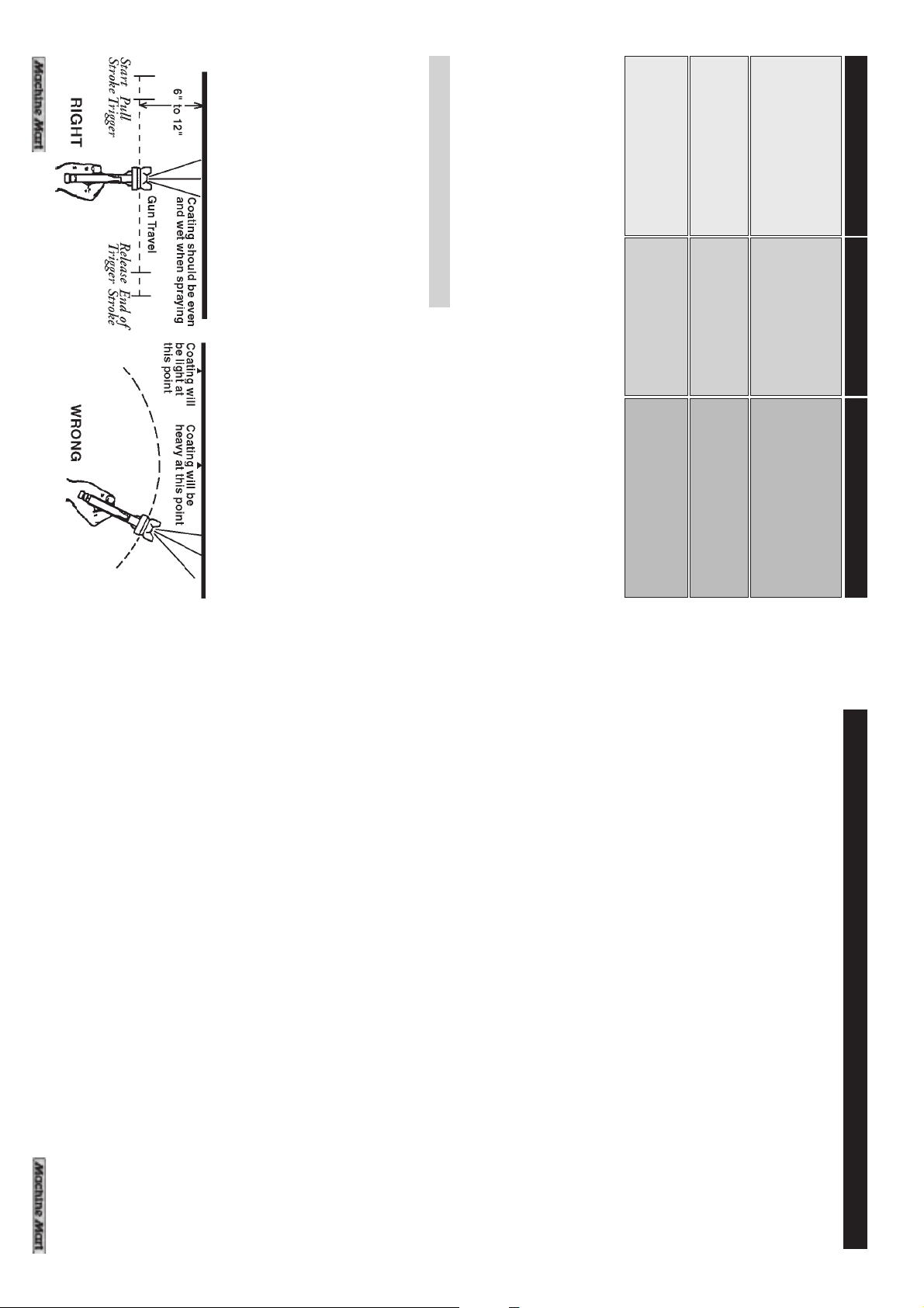
The first requirement for a good resultant finish is the proper handling of the gun.
The gun should be held perpendicular to the surface being covered and moved
parallel to it. The stroke should be started before the trigger is pulled and the
trigger should be released before the stroke is ended. This gives accurate control
of the gun and material.
The distance between gun and surface should be 6 to 12 inches depending on
material and atomizing pressure. The material deposited should always be even
and wet. Lap each stroke over the preceding stroke to obtain a uniform finish.
NOTE: To reduce overspray and obtain maximum efficiency, always spray
general guide:
with a rough texture
Finish is pitted like Air pressure too high Reduce air pressure,
Orange peel or spray too close to increase distance between
Paint dries before hitting Paint is too thin. Air Add more paint.
surface, leaving it dry pressure is too high Reduce air pressure
Paint does not atomise Paint is too thick, air Add thinners
(comes out in blobs) pressure is too low. Increase air pressure (not
3. HANDLING THE GUN
with the lowest possible atomizing air pressure.
12
Water based paints (emulsions) - 10-20% water
Oil based paints (gloss) - up to 10% white spirit thinners
Cellulose paints - up to 50% cellulose thinners
**Max. pressure for the sray gun supplied with model 5/12K is 50psi
work gun and work.
Problem Cause Correction
above 50 psi, unless
specified by paint
manuf.**
12. Ensure that any equipment/tool used in conjunction with your compressor
14. If using your compressor for paint spraying:
a) Never spray close to any source of flame or heat.
b) Always ensure that the spraying area has adequate fresh air ventilation.
c) Ensure compressor is away from overspray.
15. Make sure that children and animals are kept well away from the compressor
16. Always ensure that all individuals using the compressor have read and fully
and any equipment attached to it.
understood these Operating Instructions.
5
13. When disconnecting air hoses or other equipment from your compressor
has a safe working pressure exceeding the output pressure of the machine.
ensure that the air supply is turned off at the machine outlet and expel all
pressurised air from within the machine and other equipment attached to it.
11. The cylinder head and delivery pipes of your compressor become quite hot
supply of clean air is available to the pump unit.
tangled or wrapped around machinery etc.
during operation. Do not touch. After switching OFF remember to leave an
adequate cool down period before touching.
of the compressor is clearly stated on the machine.
receiver and the machine is disconnected from the air supply.
electrician or engineer. If you have a problem contact Machine Mart.
SAFETY PRECAUTIONS.
Before using your compressor it is in your own interest to read and pay attention to
the following safety rules
1. COMPRESSED AIR IS DANGEROUS - Never direct a jet of air at people or animals.
2. Do not operate your air compressor with any guards removed.
3. Electrical or mechanical repairs should only be carried out by a qualified
4. Before attempting any repair, ensure that pressure is expelled from the air
5. DO NOT leave the air receiver under pressure overnight, or when transporting.
6. Do not adjust or tamper with any safety valves. The maximum working pressure
7. Exercise caution when transporting the machine to avoid it tipping over.
8. Do not operate in a wet/damp environment.
9. Locate your air compressor on a firm flat surface and ensure that an adequate
10. Do not exert any strain on electrical cables and ensure that air hoses are not
Page 6
3. Switch on the main electrical supply, then open the air outlet tap (D).
6. Close the air outlet tap and connect one end of a suitable air hose to the
compressor and the other end to the equipment to be used. If spraying, DO
NOT have the paint pot attached at this stage.
5. Before connecting your airline to the compressor open and close the outlet tap
will begin to register on the pressure gauge (F). When the compressor reaches its
maximum working pressure, the motor will automatically cut out, and will restart
when the pressure has fallen by approximately 20 psi. This automatic STOP/ START
process will continue, as necessary, to maintain pressure in the receiver.
quickly, in order to blow off any condensate which may have collected NEVER put
your fingers over the outlet.....REMEMBER.....Compressed air can be DANGEROUS!
4. Start the compressor by PULLING the ON/OFF switch (B) UP to the ON position
and leave it running with the air outlet tap fully open for a short period to permit
good distribution of lubricating oil. When closing the tap, pressure in the air receiver
closing the cock once again.
3. If the machine has not been started for 24 hours or so, open the drain cock, at
NOTE: Model 5/12K is equipped with an accessory kit and is otherwise identical to Model 5/12
the base of the reservoir, to expel any air from the receiver and drain any
condensate which may have accumulated. Allow it to drain completely before
on page 4.
OPERATING INSTRUCTIONS
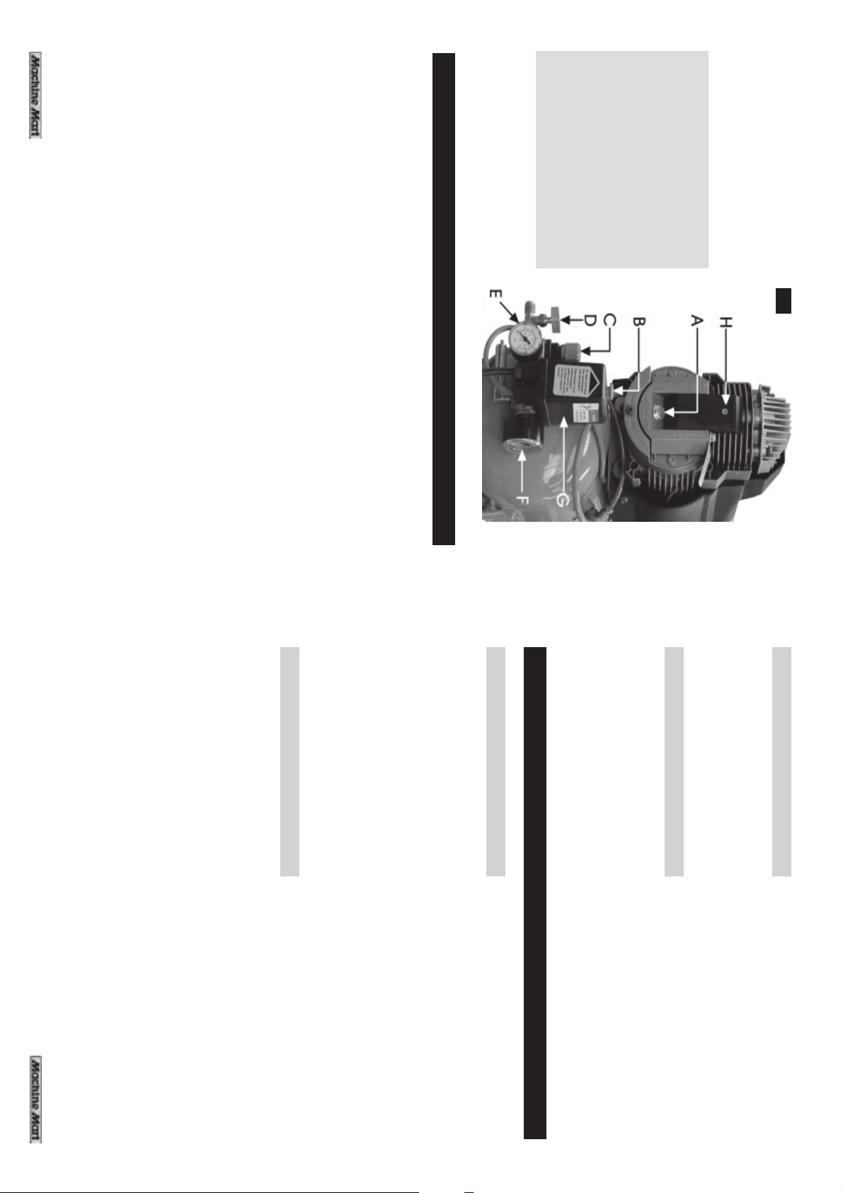
NOTE : All letters refer to fig. 1 above
1. Ensure that the electrical supply is 230V and in accordance with the instructions
2. Push the ON/OFF switch (B) DOWN to the OFF position.
C - Pressure Regulator
D - Air Outlet Tap
E - Air Outlet Pressure Gauge
F - Air Receiver Pressure Gauge
G - Pressure Switch
H - Air Filter Housing
A - Oli Filler Plug
B - ON / OFF Switch
6
It is ideal for cleaning radiators and other delicate equipment although care should
be taken to ensure that pressures cannot damage components. A low pressure
a. Achieving the correct paint viscosity. This should be done according to the
d. Some common problems are shown in the list which follows:
c. It is usually best to experiment with a couple of practice spray coats on a
piece of material with the same type of surface as the article you wish to
spray, eg. metal for a car body panel, wood for a piece of furniture etc.
b. Having mixed the paint thoroughly in a separate container, pour into the spray
2. PAINT PREPARATION
paint manufacturer’s instructions, and will vary according to the type of paint.
gun paint container through a fine filter.
REMEMBER - TIME SPENT PREPARING SAVES TIME SPENT FINISHING
e. Ensure surface to be painted is clean, dry and free from oil and dust.
the article not to be sprayed.
Check paint manufacturer’s instructions for any special surface preparation
required.
b. Connect spray gun to compressor via suitable flexible hose.
c. With no paint in spray gun, test system for air leaks.
d. Cover adjacent pieces of equipment to prevent overspray. Mask areas of
a. Ensure that the area in which you will be spraying is clean and dust free.
PAINT SPRAYING HINTS
1. GENERAL PREPARATION
The recoil hose included in this kit is fitted with male quick connectors. These can
be secured to any of the female quick connectors supplied on the other items in
this kit. To do this simply screw out the female connector until there is adequate
room in the slot to insert the male connector. Then, holding the male connector in
the centre of the female, screw the female connector clockwise to make a tight
and secure joint.
setting is required when using this tool.
5. AIR HOSE
Fig.1
This simple to operate trigger action blow gun can be used to blow away dust
and wood shavings as well as metal filings and swarf.
4. BLOW GUN
DO NOT OVERFILL SPRAY GUN PAINT CONTAINER
(three quarters full is maximum)
11
Page 7

operations.
included).
This handy, lightweight pistol grip inflator complete with air pressure gauge is suitable
for inflating tyres on motor vehicles, cycles, trailers etc.
Pull trigger to inflate, or press button on the side of grip to deflate. Always check
that tyre valve is clean before inflation.
A low pressure setting of 30 - 50 lbf/in
This gun can also be used for spraying insecticides on to plants, trees, shrubs etc.
The nozzle is adjustable to give a coarse or fine spray, feeding from either the 1
litre syphon cup or from a large container using a flexible syphon tube (not
3. TYRE INFLATOR
Be aware of the extreme fire hazard when spraying paraffin or other
flammable materials. A fine mist is not necessarily confined to the
immediate area. Take all necessary precautions.
This special gun is suitable for spraying a wide range of cleaning agents e.g. paraffin,
gunk etc., for cleaning engines, components, oil spots on driveways etc.
Preservatives such as creosote can be sprayed onto fences and sheds.
spraying jobs,
2. PARAFFIN GUN
achieving the desired results.
It is IMPORTANT to note, that the maximum pressure for the spray gun, supplied
with Model 5/12K must not exceed 50lbf/in
Basic features of this gun include a spray pattern (fan or round) adjustment screw
on the side of the gun and a material flow adjustment screw on the rear of the
gun. Experimentation with these two controls is generally the best means of
This spray gun is suitable for use with most conventional paints.
IMPORTANT
We strongly recommend that items contained in the kit supplied with Model
5/12K, be used in conjunction with appropriate eye and face protecting
1. SPRAY GUN
PROTECTION. CONSULT YOUR PAINT MANUFACTURER FOR INSTRUCTIONS
goggles, glasses or spray masks available from Machine Mart.
GENERAL GUIDANCE ON THE USE OF ACCESSORIES
SOME MODERN PAINT MATERIALS REQUIRE SPECIALIST RESPIRATORY
CAUTION
2
is generally recommended for such
Before attempting to service or carry out routine maintenance on your compressor
always ensure that the unit is unplugged from the mains electrical supply, and
that all air has been expelled from the cylinder head and air receiver by opening
both the outlet tap and drain cock.
disconnect the machine from the mains supply.
When leaving the machine for any length of time, always open the drain
cock to expel all air.
ROUTINE MAINTENANCE
3. If leaving the machine completely unattended in a domestic environment,
where there is a danger of children, or others, interfering with it in any way,
always open the drain cock to ensure all air is completely expelled and
2. IMPORTANT: ALWAYS trigger the equipment (spray gun, air tools etc.) to release
air from the air hose and cylinder head BEFORE disconnecting the spray
gun, air tools or air hosefrom machine.
1. Press down on the ON/OFF switch to the OFF position.
equipment.
SHUTTING DOWN THE COMPRESSOR
WARNING
2
, which is sufficient for most paint
accessory manufacturers recommendations for optimum operating pressures of their
NOTE :
For other airline equipment such as tyre gauges, paraffin guns etc. please refer to the
For most spray work do not exceed 50psi (unless following paint manufacturers instructions).
b. REDUCING PRESSURE
7. Set the operating pressure by adjusting the pressure regulator knob (C). To
do this pull the regulator knob upwards and adjust the pressure as follows:
a. INCREASING PRESSURE
Screw the pressure adjuster clockwise until your pressure requirementis
registered on the pressure gauge (E).
Open the outlet tap (D), and pull on the trigger, or operating mechanism
of the air tool being used, in order to expel air. Whilst doing so, turn
the pressure adjuster knob (C) anticlockwise until the gauge (E) registers
a pressure well below that which you require, then release the trigger, or
operating mechanism of the air tool, in order to stop air from exhausting.
Screw in the pressure adjuster (C) clockwise until the needle on the
pressure gauge (E) registers the pressure you require.
When the required pressure is reached, push the pressure adjuster knob
down again in order to hold the setting.
NEVER USE THE MAINS SWITCH TO STOP THE MOTOR.
710
Open the outlet tap (D) and the equipment is now ready for use.
Page 8
When components are removed for servicing ALWAYS take the opportunity to fit new seals.
In the event of air leaks, follow the procedure below:
1. Load the compressor to maximum pressure.
2. Unplug the compressor from the main electrical supply.
3. With a brush and soapy water wet all “screwed” connections. (Do not wet
4. Any leaks will show through the formation of air bubbles.
Check and clean the intake and delivery valves.
NOTE:
Replace the air intake element.
Clean all the cooling fins to ensure efficient cooling and a long working life.
• IMPORTANT: Never operate the compressor without the air intake filter fitted.
This procedure should be carried out more frequently if the compressor is used in
dusty conditions.
• Remember that a dirty filter prevents adequate aspiration and adversely
Reassemble in reverse order, taking care not to overtighten the filter plate retaining
screw.
Withdraw the filter.
Blow filter with compressed air, or wash with household detergent. Rinse thoroughly
and dry before refitting.
Remove and clean the air intake filter element as follows:
Remove the screw securing the filter cover (parts list, item 9), and gently ease off
the cover
Open the drain tap and drain the receiver of any condensate.
You should always adhere to the following service schedule.
After the first 5 hours of operation, check that all nuts and bolts are tight, paying
special care to the compressor head and crankcase.
Periodic servicing is necessary in order to keep your compressor running efficiently.
any electrical component).
8
EVERY 2 YEARS (OR 2000 HOURS):
YEARLY OR 1000 HOURS:
EVERY 6 MONTHS:
affects the efficiency of your compressor.
MONTHLY:
DAILY:
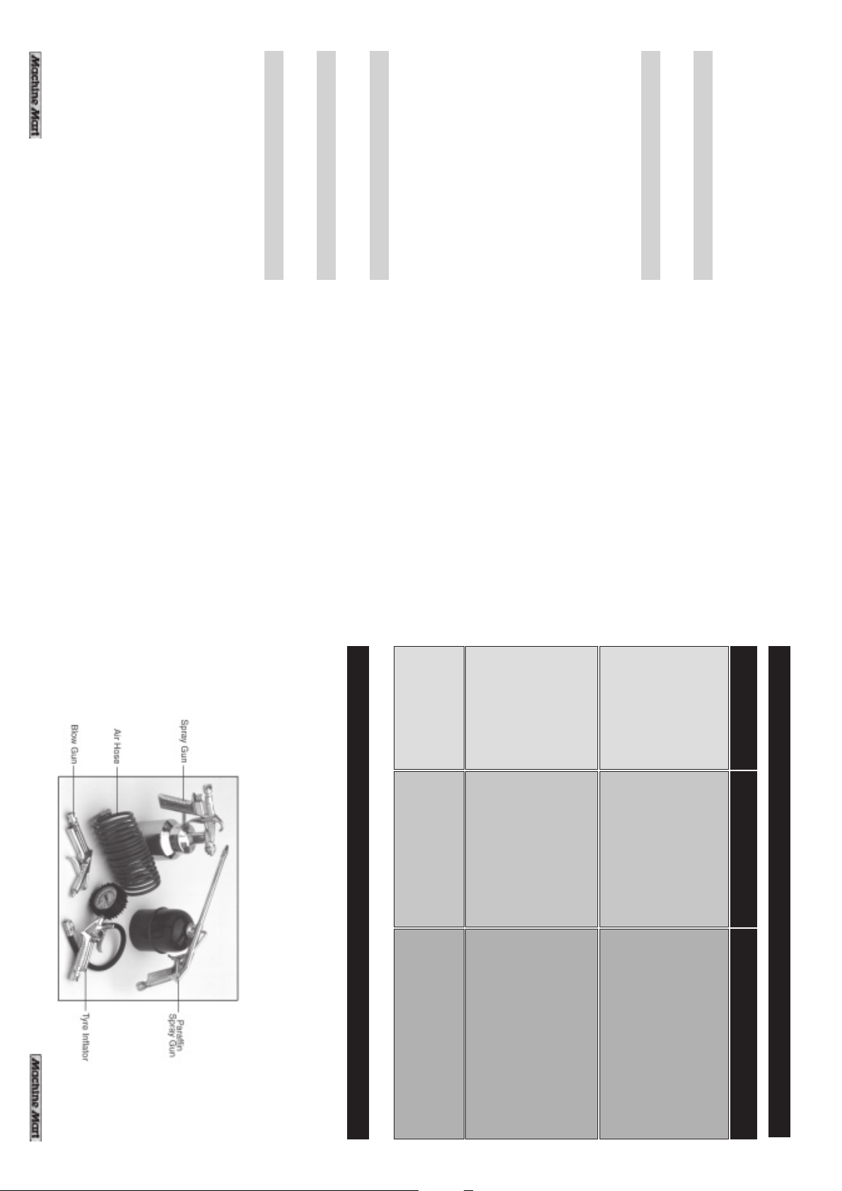
however, is supplied with the accessories shown below.
ACCESSORIES
9
approx 95 psi.
Compressor does
not start.
Air receiver charged Open drain cock to expel air.
Compressor should start again
when pressure reduces to
nearest dealer.
easily.
Carefully clean all sealing
surfaces before reassembling.
If in doubt contact your
does not reach
the set pressure
and overheats
gasket blown or valve
broken.
down, disassemble the head
and replace any broken
components.
The compressor
Motor windings burnt
out.
Compressor head
for a replacement motor.
Wait for compressor to cool
Overload cutout
switch has tripped.
Switch off and wait 5 minutes
before switching on.
Contact your Airmaster dealer
The compressor
stops and will not
start again.
Bad connections.
Check the electrical
connections.
Clean and tighten as necessary.
TROUBLE SHOOTING
PROBLEM
PROBABLE CAUSE REMEDY
Your compressor can be used with a wide range of optional accessories, for
inflating tyres, paint spraying, air brushing, stapling, blowing etc. For details,
please contact your dealer
MODEL 5/12 is the basic compressor with 12 litre receiver...Model 5/12K
 Loading...