

Page 1
WARNING: Do not use the machine without reading this manual
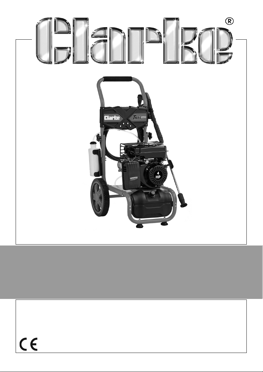
PETROL DRIVEN POWER WASHER
MODEL NO: TIGER 3000B
PART NO: 7320212
OPERATION & MAINTENANCE
INSTRUCTIONS
ORIGINAL INSTRUCTIONS GC0521
Page 2
INTRODUCTION
Thank you for purchasing this CLARKE Petrol driven power washer.
Before attempting to use this product, please read this manual thoroughly and
follow the instructions carefully. In doing so you will ensure the safety of yourself
and that of others around you, and you can look forward to your purchase
giving you long and satisfactory service.
GUARANTEE
This product is guaranteed against faulty manufacture for a period of 12
months from the date of purchase. Please keep your receipt which will be
required as proof of purchase.
This guarantee is invalid if the product is tampered with in any way, or not used
for the purpose for which it was intended.
Faulty goods should be returned to their place of purchase, no product can
be returned to us without prior permission. This guarantee does not effect your
statutory rights.
ENVIRONMENTAL RECYCLING POLICY
One of the most damaging sources of environmental pollution is oil products.
Never throw away used oil with domestic refuse or flush it down a sink or drain.
Collect any oil in a leak proof container and take it to your local waste
disposal site.
Should any components become completely unserviceable and require
disposal, plastic and metal components should be disposed for re-cycling
according to local regulations.
2
Parts & Service: 020 8988 7400 / E-mail: [email protected] or [email protected]
Page 3
GENERAL SAFETY RULES
WARNING: WATER AT HIGH PRESSURE CAN BE DANGEROUS AND CAN
CAUSE DAMAGE IF THE OPERATOR IS CARELESS. DO NOT LET PERSONNEL
OPERATE THIS PRESSURE WASHER UNLESS THEY ARE KNOW THE SAFETY
PRECAUTIONS.
1. DO NOT point the spray at other people, animals, electrical equipment or
the machine itself.
2. DO NOT hold your finger over the high pressure nozzle.
3. DO NOT let children or untrained personnel use this machine.
4. DO NOT operate the machine with any of the covers removed.
5. DO NOT try to repair this machine. Always refer to your CLARKE service
department for all repairs.
6. DO NOT supply any liquid other than water to the water inlet.
7. DO NOT use the detergent pickup facility to introduce flammable liquids/
solvents, e.g. paint thinners, petrol, oil as there is a risk of explosion.
8. ALWAYS release the remaining pressure in the system; turn off the water
supply and operate the trigger before you remove hoses or accessories.
9. ALWAYS keep the machine dry and away from the water spray.
10. ALWAYS use protective clothing and safety glasses. Loose particles and
other items can be propelled at high speed by the water spray.
11. ALWAYS hold the gun securely & expect it to ‘kick’ when the trigger is pulled
12. ALWAYS respect the requirements of the local water company. Pressure
washers may only be connected to the mains water supply if a system
separator (known as a backflow preventer) is installed in the supply hose.
13. ALWAYS disconnect from the water supply, and make sure that you drain the
system when not in use. Keep in a cool dry location.
14. ONLY use detergents that are suitable for pressure washers, we
recommend that you use CLARKE Traffic Film Remover or CLARKE Wash
and Wax (available from your dealer).
15. WARNING High pressure water jets can be dangerous, the jet must not be
directed at a person or anything that they are wearing.
16. WARNING High pressure hoses, fittings and couplings are important for the
safety of the machine. Use only hoses, fittings and couplings
recommended by the manufacturer.
17. WARNING Water that passes through a system separator (also known as a
backflow preventer) is not safe to drink.
18. DO NOT use the pressure washer if there is damage to the inlet/outer hose.
3
Parts & Service: 020 8988 7400 / E-mail: [email protected] or [email protected]
Page 4
SAFETY SYMBOLS
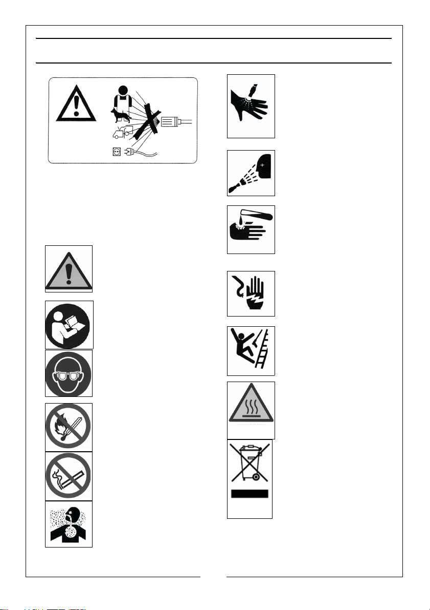
WAR NI NG : Do not direct discharge
stream at persons or animals. Keep
clear of nozzle.
WAR NI NG : Never direct spray toward
any electrical device or electrical
outlet.
General Warning, indicates
that failing to follow these
instruction could result in
injury or damage to the
machine.
To reduce the risk of injury,
read the manual before
use.
ALWAYS wear safety glasses
when using this machine.
WAR NI NG : No open flame,
open ignition source and
smoking is prohibited
WAR NI NG : No smoking
DANGER: Risk to
breathing. Engine
exhaust fumes can kill.
For outdoor use only. Work
in a well ventilated area.
WAR NI NG : Risk of injection
or severe injury. Do not
direct discharge stream at
persons or animals. Keep
clear of nozzle. This
machine is to be used
only by qualified operators.
WAR NI NG : Risk of spray
injury. Spray can propel
objects. Always wear ANSI
approved Z87.1 Safety
Glasses.
WAR NI NG : Risk of
chemical burn. Never
spray acids, corrosive or
toxic chemicals. Use only
cleaners formulated for
pressure washers.
WAR NI NG : Risk of
electrocution. Never
direct spray toward any
electrical device or
electrical outlet.
WAR NI NG : Risk of unsafe
operation. Keep
children away from this
equipment. Gun kicks
back. Hold with both hands.
WAR NI NG : Risk of hot
surfaces.
Recycle unwanted
materials instead of
disposing of them as waste.
All tools, accessories and
packaging should be
sorted, taken to a recycling
centre and disposed of in a
manner which is compatible
with the environment.
4
Parts & Service: 020 8988 7400 / E-mail: [email protected] or [email protected]
Page 5
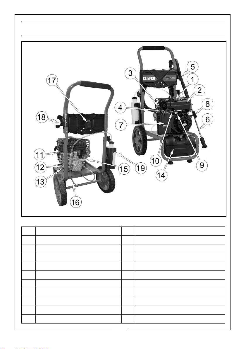
OVERVIEW
NO DESCRIPTION NO DESCRIPTION
1 Fuel Tank Cap 11 Engine On/Off Switch
2 Fuel Tank 12 Oil Filler Cap
3 Spark Plug 13 Water Outlet
4 Choke 14 Detergent Tank
5 Gun Assembly 15 Water Inlet
6 Lance Assembly 16 Bypass Drain Hose
7 Air Filter Cover 17 Hose Holder
8 Recoil Pull Start 18 Lance Holder
9 Fuel Valve 19 Priming Bottle
10 Throttle
5
Parts & Service: 020 8988 7400 / E-mail: [email protected] or [email protected]
Page 6
UNPACKING AND ASSEMBLY
Unpack your pressure washer and make sure that the following items are
present. Contact your CLARKE dealer immediately if any parts are missing or
damaged.
• 1 x Petrol Power Washer • 1 x Gun Assembly
• 2 x Wheel c/w Axle • 1 x Lance / Nozzle Assembly
• 1 x Upper Handle c/w fixings • 1 x Spark Plug Box Spanner
• 1 x Hose Bracket c/w fixings • 1 x Tommy bar
• 1 x Lance Bracket c/w fixings • 1 x Engine Manual
• 1 x Primer Bottle • 1 x Primer Bottle Holder
• 1 x Primer Bottle Bracket • 2 x Rubber feet and fixings
• 1 x Hose • 1 x 3m Inlet water hose
• 1 x Water Filter (may be
supplied already fitted)
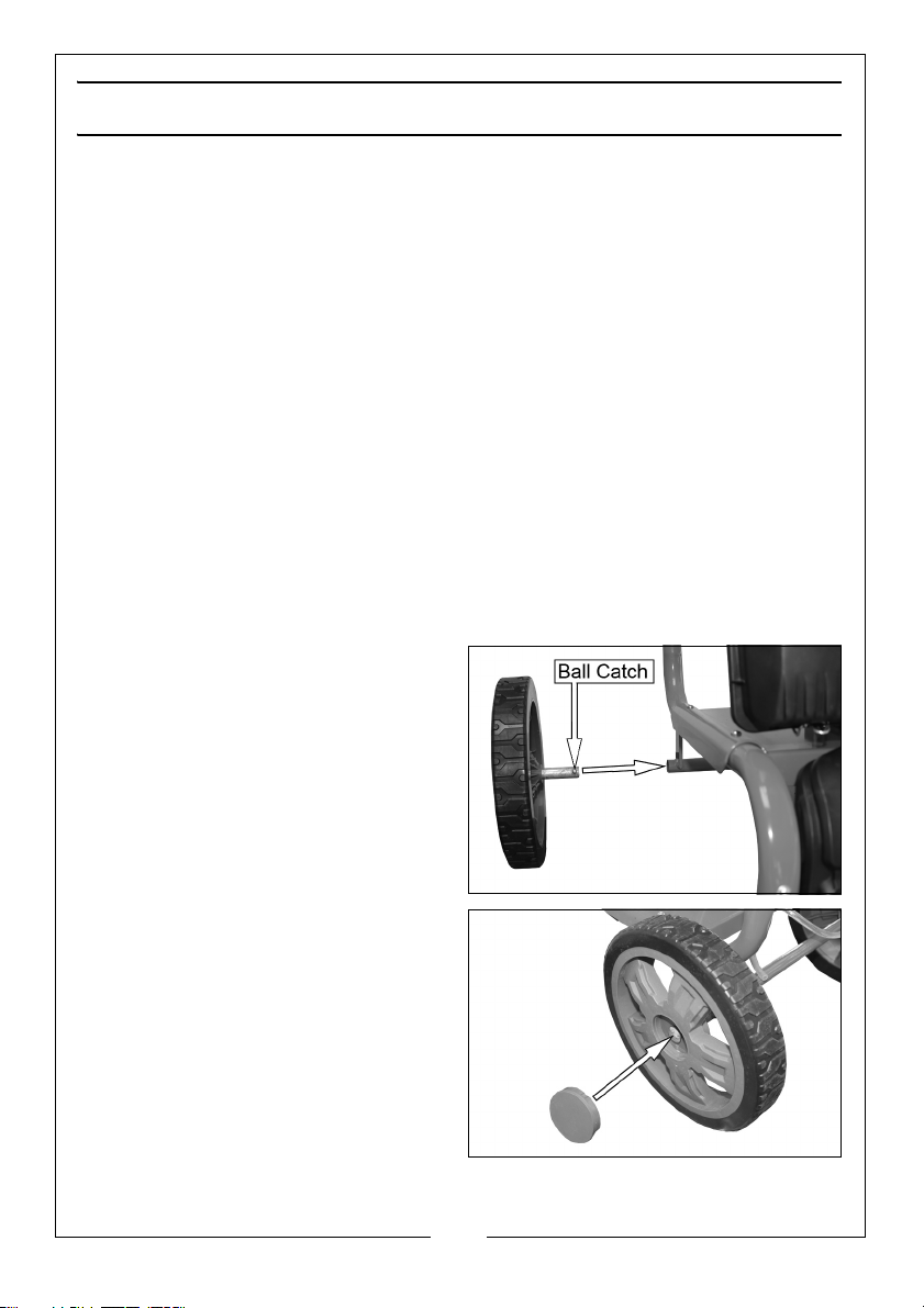
CONNECTING THE WHEELS
1. Slide the axles into the locating
tube as shown.
• Make sure the ball catch locks
into the small hole on the
bottom of the locating tube.
2. Add the 2 axle covers as shown.
6
Parts & Service: 020 8988 7400 / E-mail: [email protected] or [email protected]
Page 7
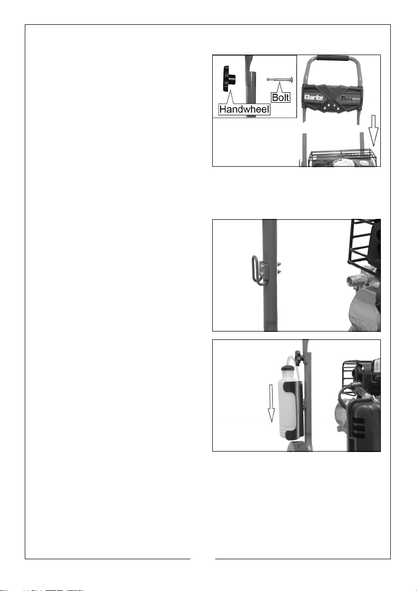
CONNECTING THE HANDLE
1. Slide the upper handle into
position as shown.
2. Secure using a bolt and
handwheel.
• The handwheel should be on
the outside.
FITTING THE WATER BOTTLE
NOTE: The water bottle is only used when using the drawing water from an
unpressurised source such as a water butt. See page 16.
1. Fit the bracket to the frame as
shown using the bolts, nuts and
washers supplied.
2. Slide the bottle holder over the
bracket and place the bottle in
the holder.
7
Parts & Service: 020 8988 7400 / E-mail: [email protected] or [email protected]
Page 8
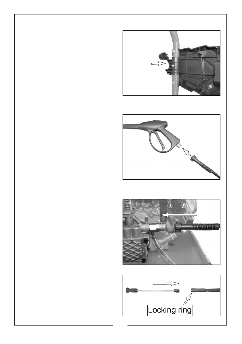
FITTING THE LANCE/HOSE HOLDER
Fit the holders into the positions
shown and secure using the washers
and nuts provided.
CONNECTING THE HIGH PRESSURE HOSE
CONNECT THE HOSE TO THE GUN
1. Screw the high pressure hose onto
the gun assembly.
• Tighten the connector, hand
tight only. Do not use a
spanner.
NOTE: Make sure the connection is
secure.
CONNECT THE HOSE TO THE PRESSURE WASHER
1. Screw the hose on to the pressure
washer.
• Tighten the connector, hand
tight only, Do not use a
spanner.
NOTE: Make sure the connection is
secure.
ASSEMBLING THE LANCE
Connect the spray lance to the gun
assembly and tighten securely by
turning the locking ring.
8
Parts & Service: 020 8988 7400 / E-mail: [email protected] or [email protected]
Page 9
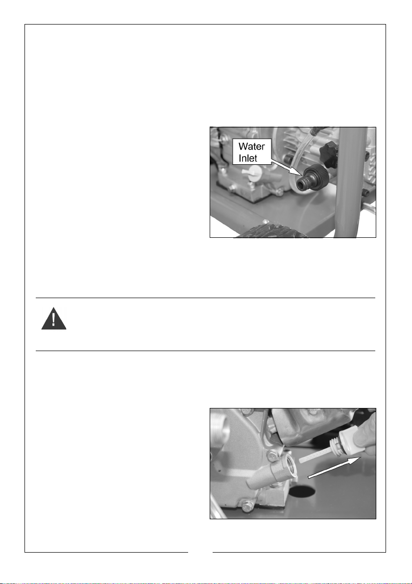
CONNECTING THE WATER SUPPLY
Always follow the regulations of your local water supplier. The pressure washer
must never be connected to the drinking water supply without using a system
separator (also known as a backflow preventer) available from most
hardware stores.
NOTE: Water that has flowed through a system separator is considered non-
drinkable.
1. Connect a water supply hose (not
supplied) to the water inlet.
• Make sure that the water filter is
installed behind the hose
connector on the water inlet
NOTE: Use a good quality fibre-
reinforced water hose with a
standard coupling.
NOTE: This machine has the ability to
draw its own water, meaning
you can use water not under pressure such as rainwater collected in a
water butt. See page 16.
BEFORE USE
WARNING: STAND THE PRESSURE WASHER ON LEVEL GROUND WITH THE
ENGINE SWITCHED OFF.
WARNING: TAKE CARE NOT TO TOUCH ANY HOT PARTS OF THE PRESSURE
WASHER WHEN CHECKING THE OIL LEVEL.
IMPORTANT: The engine is supplied without any oil in it and must be filled to
the correct level before use, see below.
ENGINE OIL
1. Turn the oil filler cap anticlockwise
and remove it from the engine,
wipe the integral dipstick with a
clean cloth.
9
Parts & Service: 020 8988 7400 / E-mail: [email protected] or [email protected]
Page 10
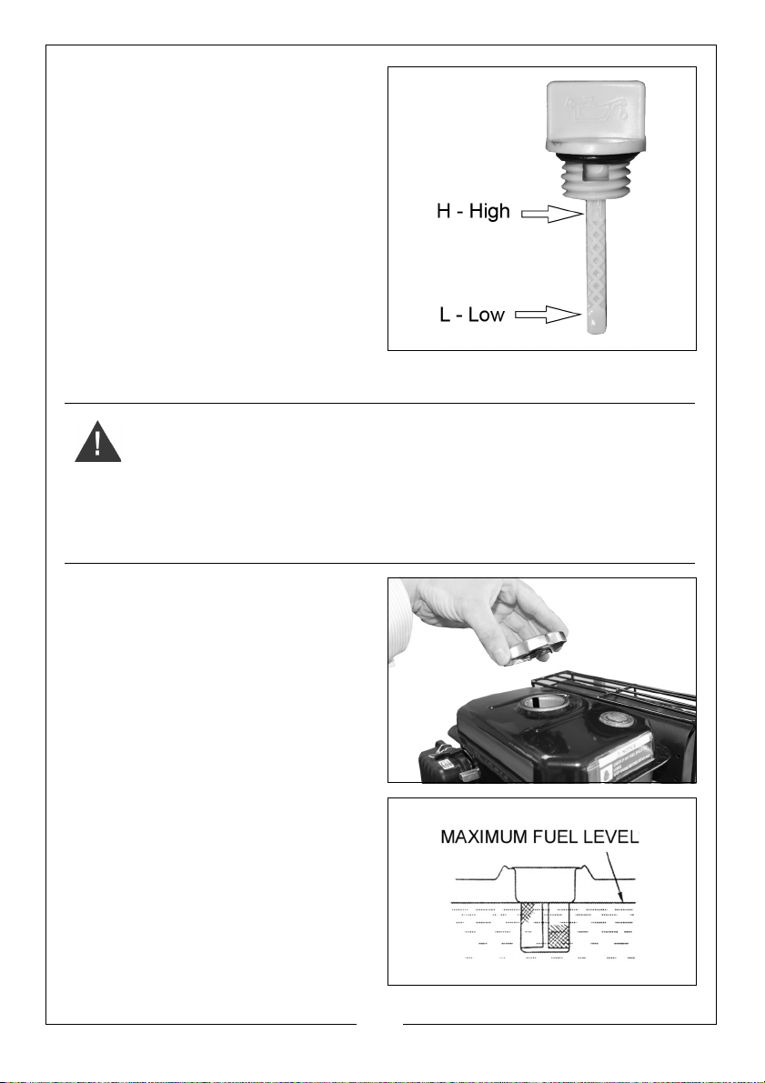
2. Insert the oil filler cap back into
place and then remove it again.
3. If the oil reads low on the dipstick,
add oil to the oil reservoir (Max
0.6L).
• We recommend the use of
SAE10W-30 oil.
• Do not overfill the oil reservoir.
4. Replace the oil filler cap.
NOTE: Running the engine with
insufficient oil will cause
engine damage.
FUEL
WARNING: REFUEL IN A WELL-VENTILATED AREA, AWAY FROM ANY
SOURCES OF IGNITION.
WARNING: IF THE ENGINE HAS BEEN RUNNING, ALLOW IT TO COOL
BEFORE REFUELING.
WARNING: DO NOT LEAVE FUEL WITHIN THE REACH OF CHILDREN.
WARNING: WARNING: REFUEL CAREFULLY TO AVOID SPILLING FUEL.
1. Remove the fuel tank cap.
• Just inside the fuel tank is a fuel
strainer, which should be
checked periodically and any
contaminants which have
accumulated must be
removed.
2. Pour unleaded petrol through the
fuel strainer and into the fuel tank.
• Do not fill above the fuel
strainer shoulder.
• Use unleaded petrol with a
pump octane rating of 86 or
higher.
3. Replace the fuel filler cap
securely.
10
Parts & Service: 020 8988 7400 / E-mail: [email protected] or [email protected]
Page 11
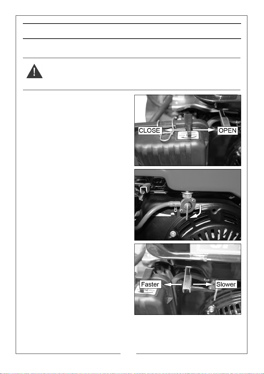
STARTING YOUR PRESSURE WASHER
1. Turn the water supply on, making sure that the tap is fully open.
WARNING: FAILURE TO TURN ON THE WATER COULD CAUSE DAMAGE TO
THE PRESSURE WASHER.
2. Set the choke lever to the CLOSE
position.
3. Set the fuel supply valve to the ON
position.
4. Slide the throttle lever to the left
approximately 3/4 of the way.
11
Parts & Service: 020 8988 7400 / E-mail: [email protected] or [email protected]
Page 12
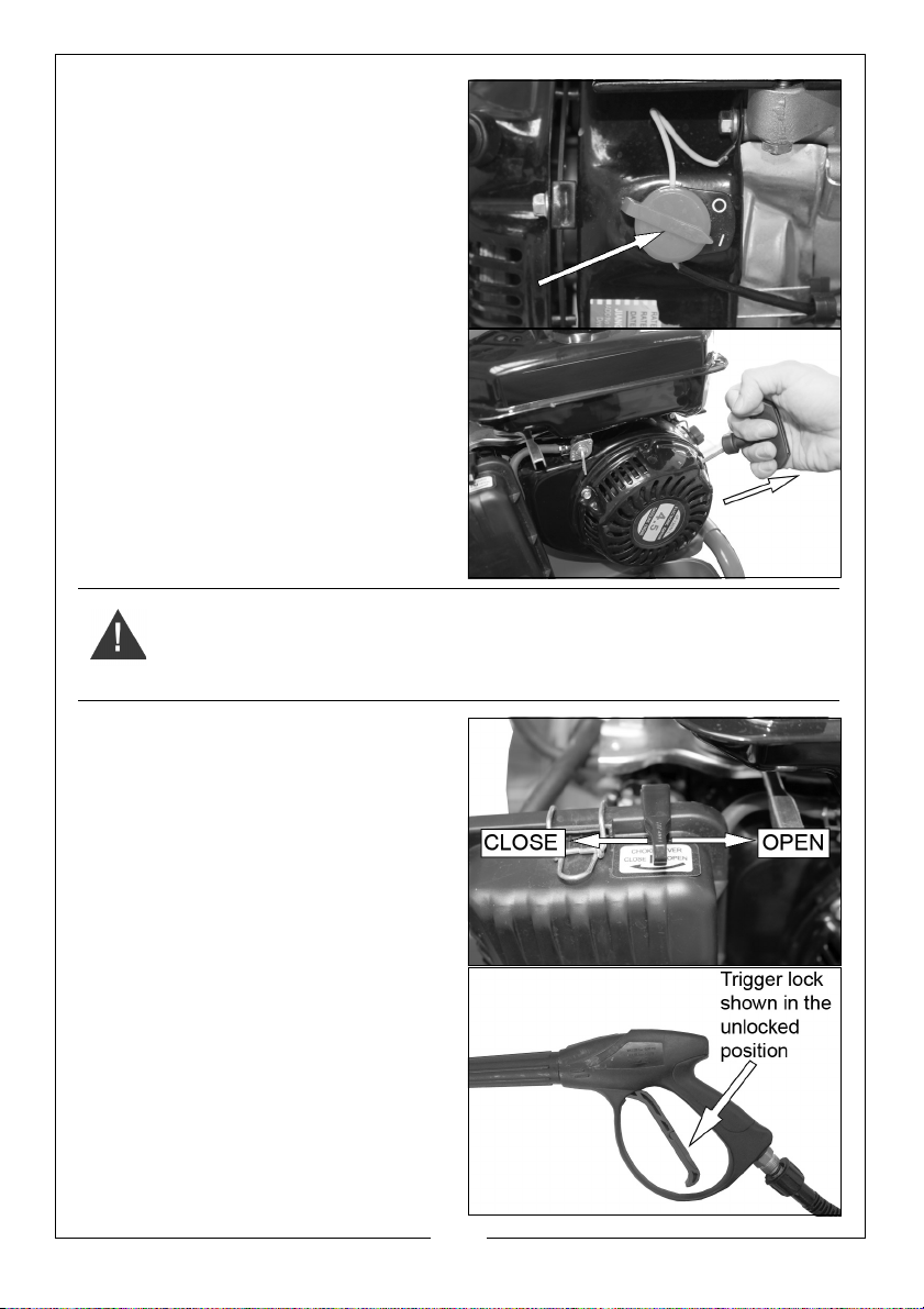
5. Set the engine switch to the on (I)
position.
6. Pull the recoil starting handle
lightly until you start to feel
resistance and then pull up
sharply to start the engine.
• You may have to do this more
than once.
WARNING: ONCE THE PRESSURE WASHER ENGINE HAS STARTED, RELEASE
THE STARTING HANDLE SLOWLY TO AVOID INJURY/DAMAGE AS IT
RECOILS.
7. 7. Once the engine has warmed
up, slide the choke lever to the
OPEN position.
• The pressure washer is now
ready for use.
8. Release the trigger lock.
9. Ensuring that you have a firm
footing and that you are also
holding the gun assembly and
spray lance firmly, pull the trigger
on the gun to start water flow.
• The lance and gun will kick
back when the trigger is first
pulled.
12
Parts & Service: 020 8988 7400 / E-mail: [email protected] or [email protected]
Page 13
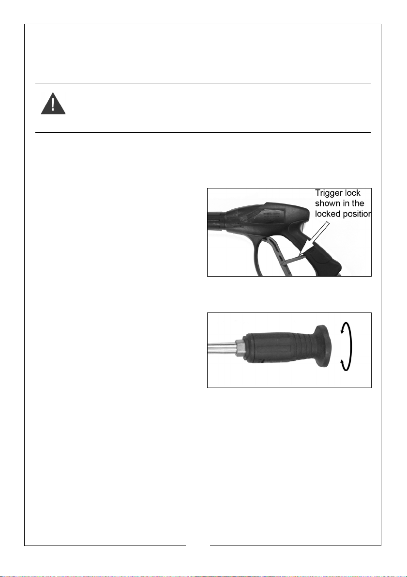
INTERRUPTING OPERATION
1. Release the trigger.
NOTE: The pressure washer will automatically go into bypass mode.
WARNING: DO NOT ALLOW THE UNIT TO OPERATE IN BYPASS MODE FOR
MORE THEN TWO MINUTES AT ANY TIME. TURN THE UNIT OFF IF IT IS NOT
GOING TO BE USED FOR LONGER THAN THIS. SEE PAGE 14.
NOTE: If you notice water coming from the drain tube attached to the pump,
please note that this is a safety feature and should be expected, it
cools the pump by releasing some of the hot water within the pump
and replacing it with fresh ‘cool’ water.
2. Rotate the trigger lock to the
locked position.
ADJUSTING THE SPRAY NOZZLE
The nozzle is adjustable to allow you to adjust the water delivery from a narrow
jet of water to a wide spray. To adjust the nozzle, proceed as follows:
1. Hold the shaft of the lance in one
hand.
2. Twist the nozzle with the other
hand.
• The spray varies between
narrow and wide as you turn
the nozzle.
ADJUSTING THE PRESSURE
The machine output is preset at the factory. To lower the contact pressure:
1. Back away from the surface to be cleaned. The further away you are the
less the pressure will be on the surface being cleaned.
2. Reduce the speed of the engine using the throttle. Slow the engine down
and the water pressure will also go down.
3. Adjust the spray to a wider angle.
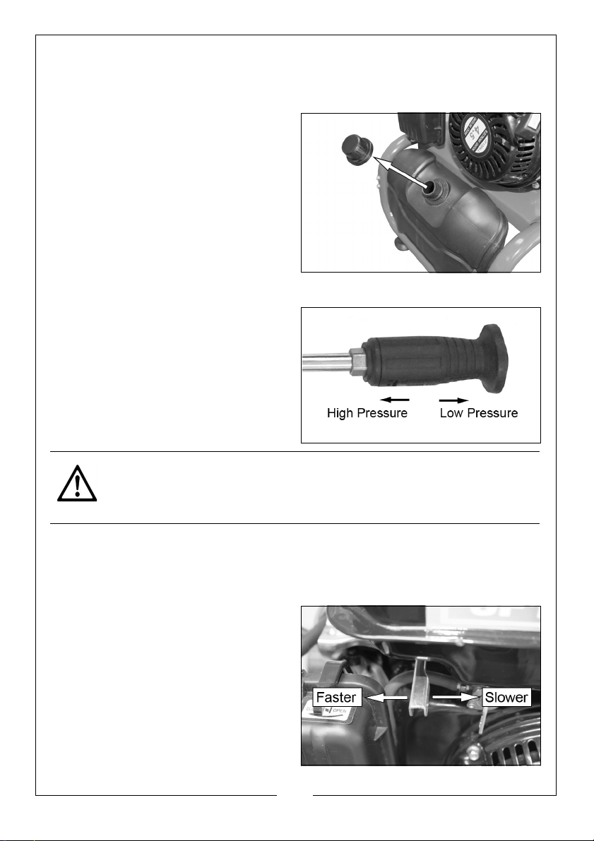
4. Hold the rear of the nozzle and slide the front of the nozzle forwards to low
pressure and backwards for high pressure. See page 14.
13
Parts & Service: 020 8988 7400 / E-mail: [email protected] or [email protected]
Page 14
APPLYING DETERGENTS AND CLEANING AGENTS
To improve the cleaning performance, you can introduce chemical cleaning
agents (detergents) to the water jet using the detergent pickup hose.
1. Remove the detergent tank cap.
2. Fill the tank with a suitable CLARKE
detergent and replace the cap.
• Only use detergents
recommended for use with
pressure washers, such as
CLARKE Traffic Film Remover
which is a powerful low
foaming agent for car
cleaning, patio cleaning etc.,
or CLARKE Wash & Wax, both available from your CLARKE dealer.
3. Hold the rear of the nozzle on the
high pressure lance and slide the
front of the nozzle forwards to low
pressure.
4. Spray the detergent onto the
vehicle, patio etc.
• Allow the detergent a little time
to work itself into the grime.
CAUTION: IF YOU GET CLEANING FLUID IN YOUR EYES, RINSE THEM
IMMEDIATELY WITH PLENTY OF FRESH CLEAN WATER. AND SEEK MEDICAL
ADVICE IF REQUIRED.
• To rinse, slide the front of the nozzle on the lance back towards the
handle and use the pressure washer as normal.
SHUTTING DOWN
1. After each use, if you have
applied chemicals, slide the front
of the nozzle on the lance back
towards the handle and operate
the pressure washer for a short
time to flush the hoses.
2. Move the throttle control lever to
the right.
14
Parts & Service: 020 8988 7400 / E-mail: [email protected] or [email protected]
Page 15
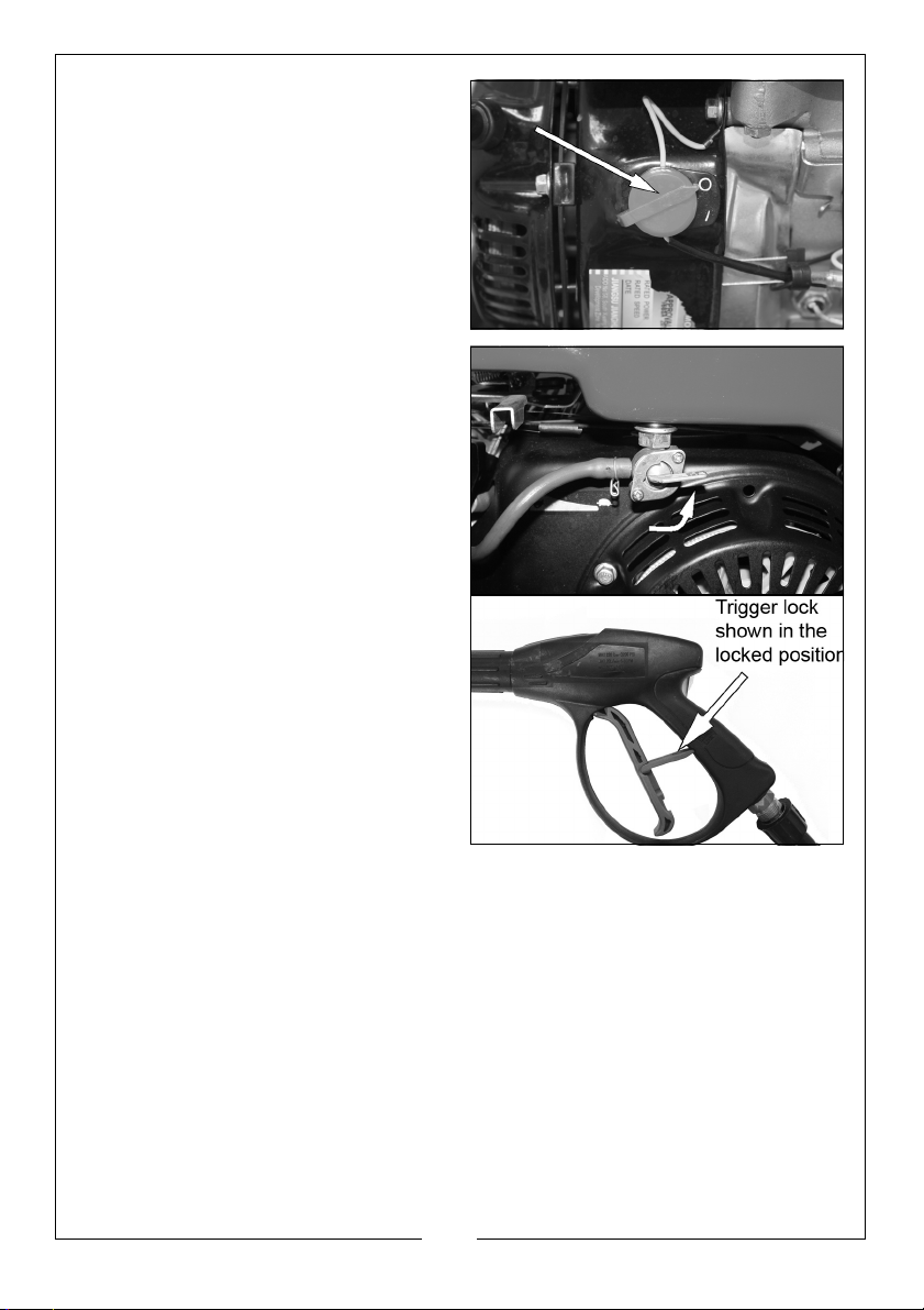
3. Turn off the engine switch, to the
off (0) position.
4. Turn water supply off at the tap.
• NEVER turn the water off with
the engine running.
5. Release the pressure in the pump
and hose by squeezing the trigger
for a few seconds until no more
water comes out of the nozzle.
6. Turn the fuel supply valve to the
off position.
7. Rotate the trigger lock to the
locked position.
15
Parts & Service: 020 8988 7400 / E-mail: [email protected] or [email protected]
Page 16
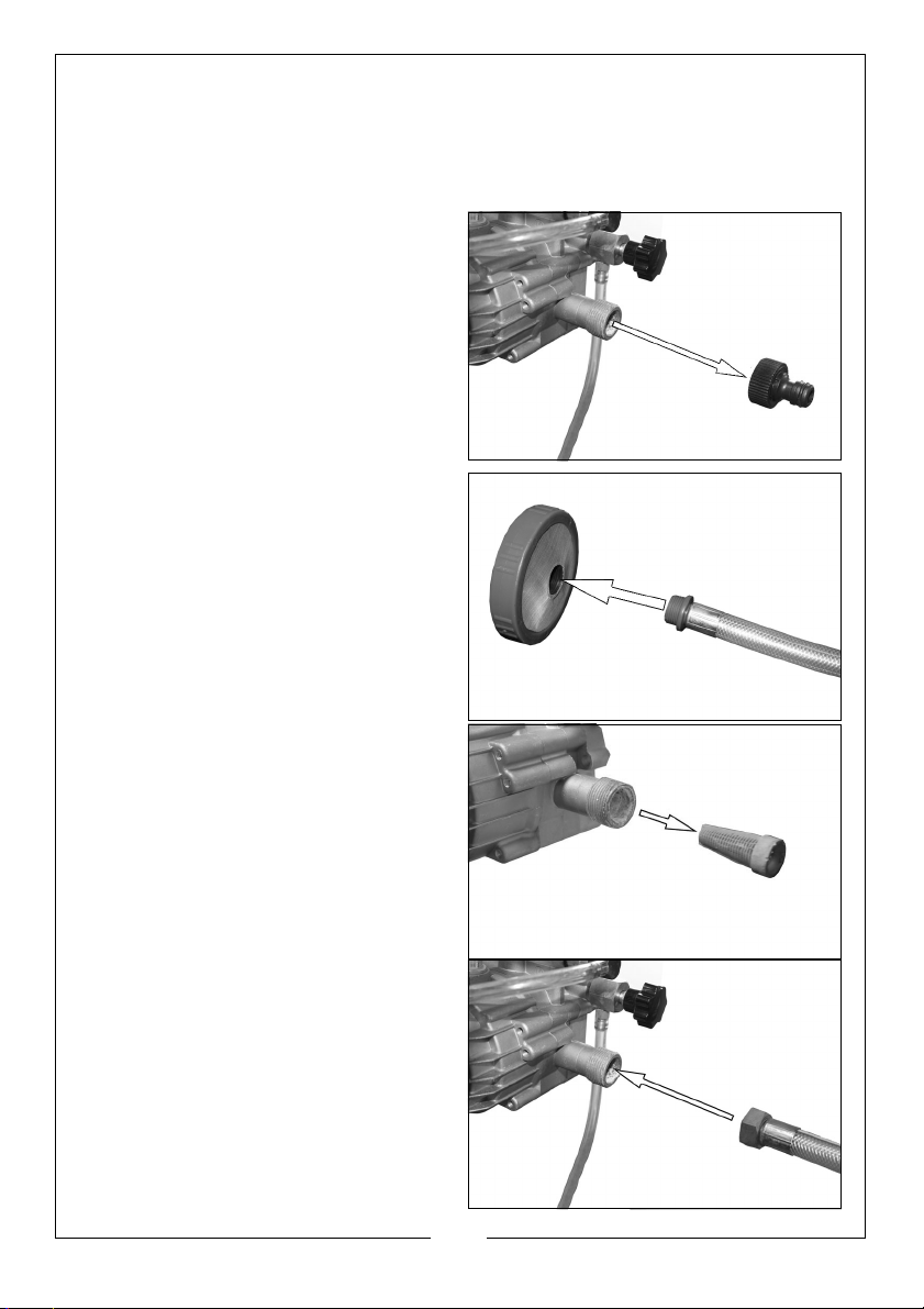
WATER BUTT CONNECTION
This machine has the ability to draw its own water, meaning you can use water
not under pressure such as rainwater collected in a water butt.
To do this you must carry out the following procedure.
1. Remove the quick connector
from the water inlet.
2. Attach the filter to the end of the
braided pipe supplied.
3. Remove the water inlet filter.
4. Connect other end of the braided
pipe to the water inlet.
16
Parts & Service: 020 8988 7400 / E-mail: [email protected] or [email protected]
Page 17
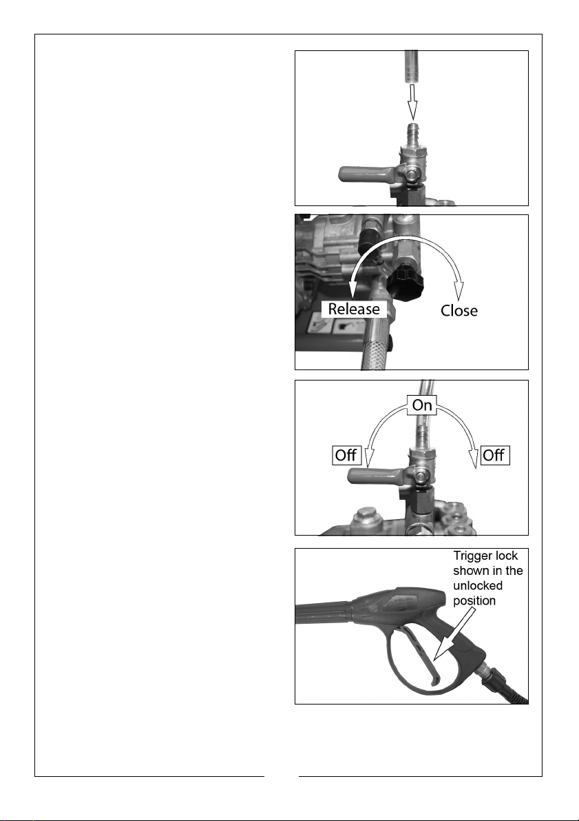
5. Fill the priming bottle with water.
6. Connect the hose from the bottle
to the self-suction valve shown.
7. Place the filter into the water
source and start the pressure
washer, See “Starting your
pressure washer” on page 11.
8. Release the exhaust valve.
9. Turn the self-suction valve to the
on position.
10. Release the trigger lock and pull
the trigger.
11. When the water spray is at high
pressure, close the exhaust valve
and set the suction valve to the
OFF position.
NOTE: If the water butt runs out of
water, the pressure washer will
need to be primed before use
by repeating steps 4-10.
17
Parts & Service: 020 8988 7400 / E-mail: [email protected] or [email protected]
Page 18
STORAGE
1. Disconnect the high pressure hose and drain all water from the hose.
2. Coil the hose and store the gun/lance in the holders located on the side
frame of the pressure washer.
STORAGE PROCEDURE
Make sure that the pressure washer has been thoroughly cleaned before
storing it in a clean dry place. For long term storage See page 20.
MAINTENANCE
CLEANING THE NOZZLE
1. Switch off the pressure washer and the water supply.
2. Pull the trigger to release any water pressure.
3. Disconnect the lance from the gun assembly.
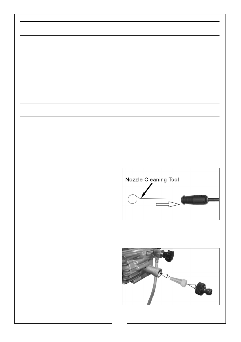
4. Remove all blockages with the
nozzle cleaning tool provided and
back flush with clean water.
5. Run water into the end of the
lance for 30 seconds to back flush
loose particles.
6. Reconnect the lance to the gun
assembly and turn on the water
supply.
CLEANING THE WATER INLET FILTER
1. Remove the filter from the water
inlet of the pump as shown.
2. Clean the filter by flushing both
sides with water.
3. Replace the filter into the water
inlet.
• Do not operate without the
filter properly installed.
18
Parts & Service: 020 8988 7400 / E-mail: [email protected] or [email protected]
Page 19
CLEANING THE FUEL STRAINER
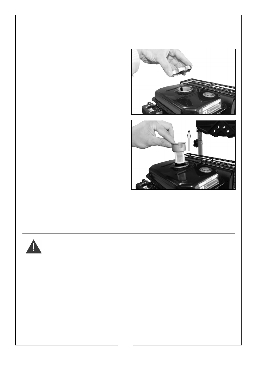
Just inside the fuel tank is a fuel strainer, check this periodically and remove
any contaminants which may have accumulated.
1. Open the fuel tank cap.
2. Remove the fuel strainer.
3. Flush away any contaminants.
4. Replace the fuel strainer.
• Do not operate the pressure
washer without the fuel strainer
properly installed.
CLEANING THE AIR FILTER
1. Remove the two screws on the air
filter cover.
2. Remove the air filter cover
3. Remove the air filter element.
4. Wash it in a solution of warm water and mild detergent.
WARNING: DO NOT USE FLAMMABLE SOLVENTS OR PETROL TO CLEAN THE
AIR FILTER
5. Rinse thoroughly and leave it to dry. Once it is completely dry, immerse the
filter in clean engine oil and squeeze the filter to remove excess oil.
• If the air filter is damaged contact CLARKE spare parts department
for a replacement.
6. Replace the filter into its original position and refix the air filter cover.
19
Parts & Service: 020 8988 7400 / E-mail: [email protected] or [email protected]
Page 20
CHANGING THE SPARK PLUGS
CAUTION: ALLOW THE ENGINE TO COOL BEFORE REMOVING THE SPARK
PLUG.
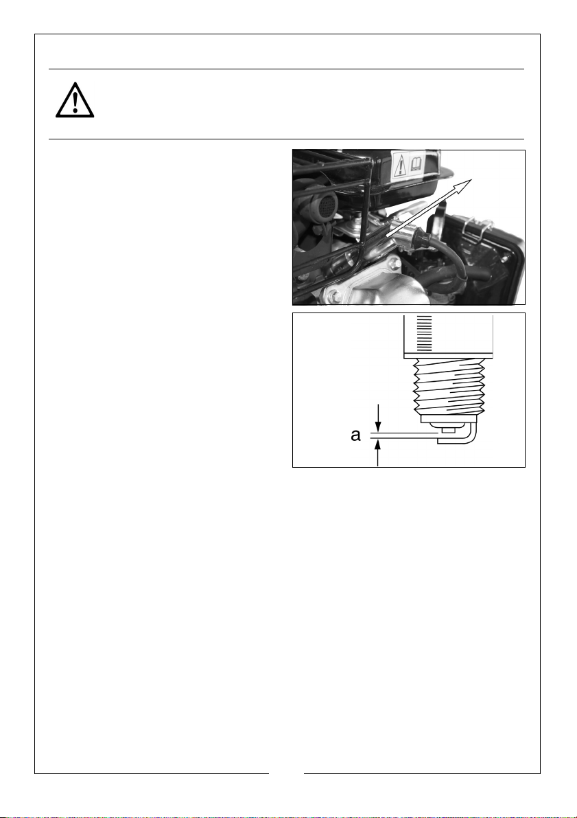
1. Remove the spark plug cap from
the spark plug.
2. Use the supplied spark plug
spanner to remove the spark plug.
3. Remove any carbon that has
accumulated around the sparkplug.
4. Check the overall condition of the
spark plug and replace if
necessary.
5. Check the spark plug gap (a), it
should be between 0.7 and 0.8
mm, adjust if necessary.
6. Reinstall the spark plug and refit
the spark plug cap.
LONG TERM STORAGE
For long term storage;
1. The petrol tank should be drained.
• Ensure that the engine is cold before draining the tank.
2. Remove the fuel tank cap and use a pump type sIphon to drain the petrol
into an appropriate, clean container.
• Do not store petrol for long periods of time.
• Dispose of excess petrol in an environmentally safe way. Your local
recycling centre can advise you on the best method of disposal.
3. After the petrol tank has been drained, start the engine and allow it to use
any petrol that may remain in the engine, or fuel pipe.
4. Make sure that the power washer has been thoroughly cleaned before
storing it in a clean dry place.
20
Parts & Service: 020 8988 7400 / E-mail: [email protected] or [email protected]
Page 21
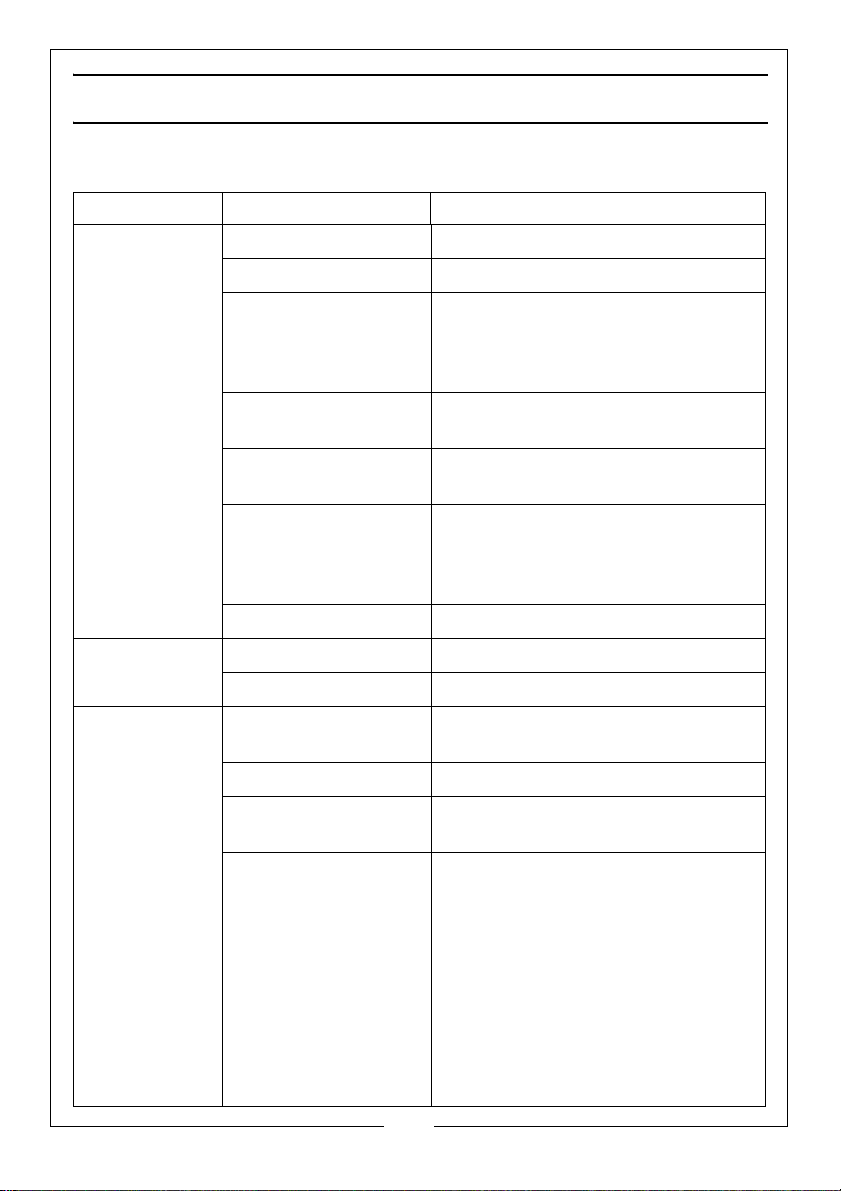
TROUBLESHOOTING
If the following does not solve your problem contact the CLARKE service dept.
PROBLEM CAUSE SOLUTION
Engine will not
start (see
engine manual
for further
engine
troubleshooting
No fuel. Add fuel.
Low oil. Add oil.
Pressure builds up
after two pulls on the
recoil starter or after
initial use.
Squeeze the gun trigger to relieve
the pressure.
Oil leaking at
the pump
Lack of
pressure (initial
use)
Spark plug lead not
attached.
Engine switch is in the
OFF position.
Choke lever is set to
the on position when
the engine is already
warm.
Fuel valve closed. Open the fuel valve.
Oil seals worn. Have them replaced by your dealer.
Worn O-rings. Have them replaced by your dealer.
Leak in the high
pressure hose fitting.
Nozzle is obstructed. Clear the nozzle.
Water filter screen is
clogged.
Air in the hose. Turn off the engine.
Attach the spark plug lead.
Set the engine switch to the ON
position.
Set the choke lever to the OFF (right)
position.
Tighten the fitting, use sealant tape if
required.
Remove and clean the filter.
Turn off the water supply.
Disconnect the water source from
the pump inlet and turn on the water
source to expel the air from the hose.
When all the air has been removed,
turn off the water supply and
reconnect the hose.
Turn on the water supply and pull the
trigger to expel any air in the gun/
lance.
21
Parts & Service: 020 8988 7400 / E-mail: [email protected] or [email protected]
Page 22
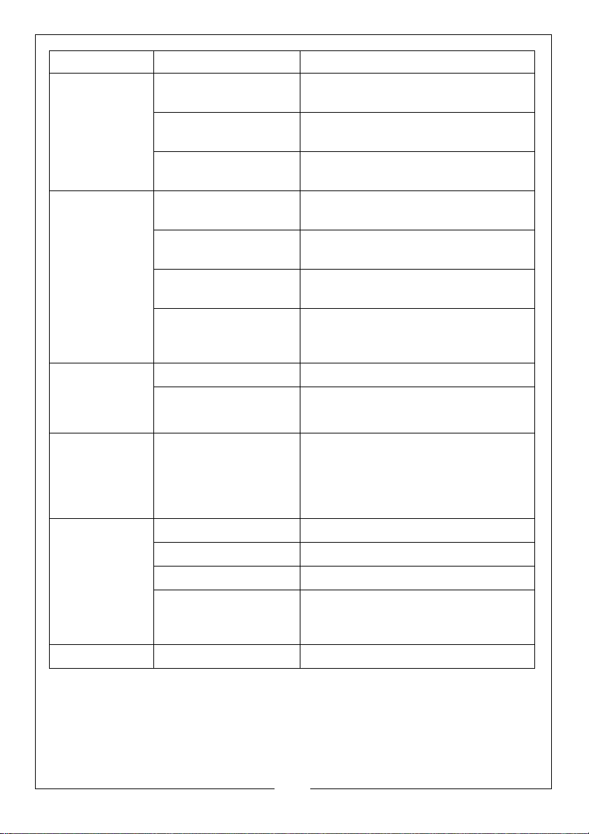
PROBLEM CAUSE SOLUTION
Lack of
pressure (initial
use) continued
Choke lever is in the
ON position.
Throttle control lever is
Set the choke lever to the OFF
position.
Move the throttle control lever to left.
not set high enough.
High pressure hose is
too long.
Make sure the high pressure hose is
under 100 feet.
Will not draw
chemicals
Lack of
pressure (after
a period of
normal use)
Water leaking
from the drain
hose
Water leaking
at the pump
Chemical filter is
Clean the filter.
blocked.
Chemicals being used
are too thick.
High pressure hose is
too long.
Chemical build up
inside the chemical
Dilute the chemicals which should
have the consistency of water.
Use a longer supply hose instead of a
longer high pressure hose.
Have the parts cleaned or replaced
by your dealer.
injector.
Worn seal or packing. Have them replaced by your dealer.
Worn or obstructed
Have them replaced by your dealer.
valves.
Pump is overheating This is a safety feature and should be
expected. It cools the pump by
releasing some of the hot water
within the pump and replacing it with
fresh ‘cool’ water.
Loose connections. Tighten.
Piston rings worn. Have it replaced by your dealer.
Damaged O-rings. Have it replaced by your dealer.
Pump head or tubes
damaged from
Have it replaced by your dealer. See
“Storage” on page 18.
freezing.
Pump pulsates Nozzle obstructed. Clear the nozzle.
22
Parts & Service: 020 8988 7400 / E-mail: [email protected] or [email protected]
Page 23
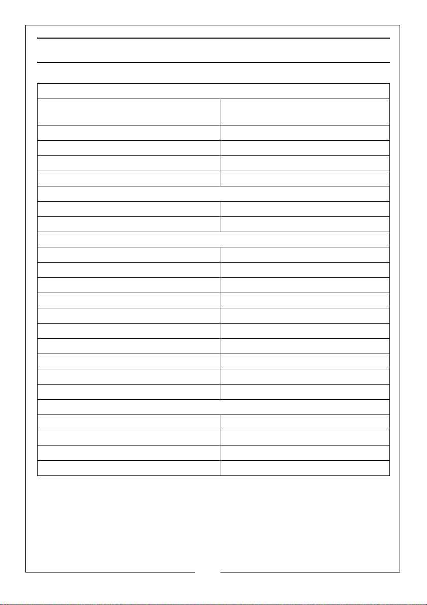
SPECIFICATIONS
ENGINE
Engine type Petrol (unleaded). OHV Single
cylinder 4 stroke forced air cooling
Capacity/displacement: 196 cc
Oil Capacity 0.6 L
Lubrication Grade SAE10W-30
Fuel Tank Capacity (Litres) 4L
WATER CONNECTION
Max. Feed Temperature 60 °C
Max. Feed Pressure 3-6 Bar
PERFORMANCE DATA
Maximum Pump Pressure 200 Bar
Working Pressure 150 Bar
Maximum Water Flow 8 I/min
NOISE & VIBRATION
Sound Pressure Level LpA 86.7 dB(A)
Sound Power Level LWA 103 dB(A)
Guaranteed Sound Power Level LWA 106 dB(A)
Uncertainty Factor K 2.98
Vibration 3.398 m/s
Uncertainty Factor K 1.5
DIMENSIONS
Length 540 mm
Width 630 mm
Height 1020 mm
Weight 31 kg
23
Parts & Service: 020 8988 7400 / E-mail: [email protected] or [email protected]
Page 24
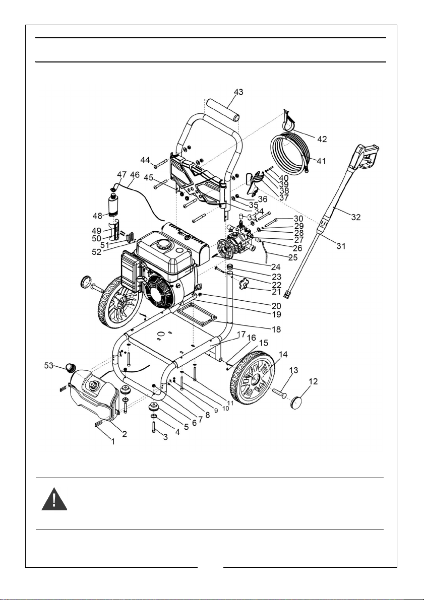
EXPLODED DIAGRAM
WARNING: TO ENSURE MACHINE SAFETY, USE ONLY ORIGINAL SPARE
PARTS FROM CLARKE INTERNATIONAL.
24
Parts & Service: 020 8988 7400 / E-mail: [email protected] or [email protected]
Page 25
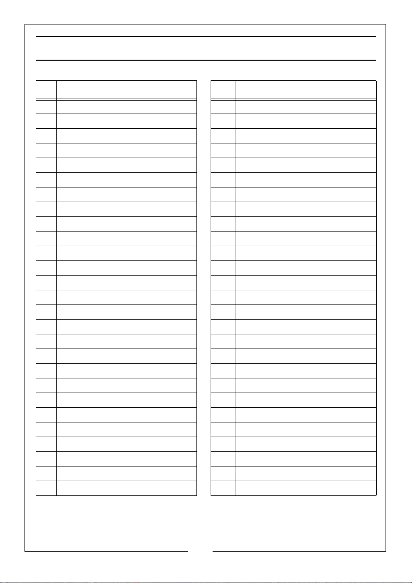
COMPONENT PARTS LIST
NO DESCRIPTION NO DESCRIPTION
1 Cross pan head screw M6x40 28 Flat Washer Ø8
2 Detergent Tank 29 Spring Washer Ø8
3 Inner Hexagon Bolt M8x42 30 Inner Hexagon Bolt M8x25
4 Rubber Foot Washer 31 Lance
5 Rubber Foot 32 Gun
6 Frame 33 Overflow Valve Cover
7Locknut M8 34Panel
8 Flat Washer Ø6 35 Locknut M8
9 Locknut M6 36 Flat Washer Ø5
10 Inner Hexagon Bolt M8x45 37 Gun Holder
11 Flat Washer Ø8 38 Flat Washer Ø5
12 Hub Cover 39 Spring Washer Ø5
13 Wheel Shaft 40 Cross Pan Head Screw M5x16
14 11" Plastic Wheel 41 Hose
15 Clip 42 Hose Strap
16 Spring Wire 43 Handle Foam
17 Baseboard 44 Cross Pan Head Screw M5x42
18 Engine Cushion 45 Nozzle Grommet
19 Engine 46 Injection Hose
20 Locknut M8 47 Bottle Cap
21 Hand Wheel 48 Bottle
22 Square Neck Bolt 49 Bottle Frame
23 Plug 50 Cross Pan Head Screw M5x40
24 Flat Key 51 Bottle Holder
25 Leading Sleeve 52 Locknut M8
26 Drain Hose (320mm) 53 Detergent Tank Cap
27 Drain Hose (320mm)
25
Parts & Service: 020 8988 7400 / E-mail: [email protected] or [email protected]
Page 26
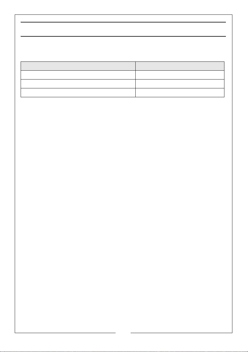
ACCESSORIES
The range of accessories listed below may be purchased from your CLARKE
dealer.
ITEM PART NUMBER
5 Litres Detergent (Traffic Film Remover) 3050821
25 Litres Detergent (Traffic Film Remover) 3050820
5 Litres Wash ‘n’ Wax 3050815
26
Parts & Service: 020 8988 7400 / E-mail: [email protected] or [email protected]
Page 27
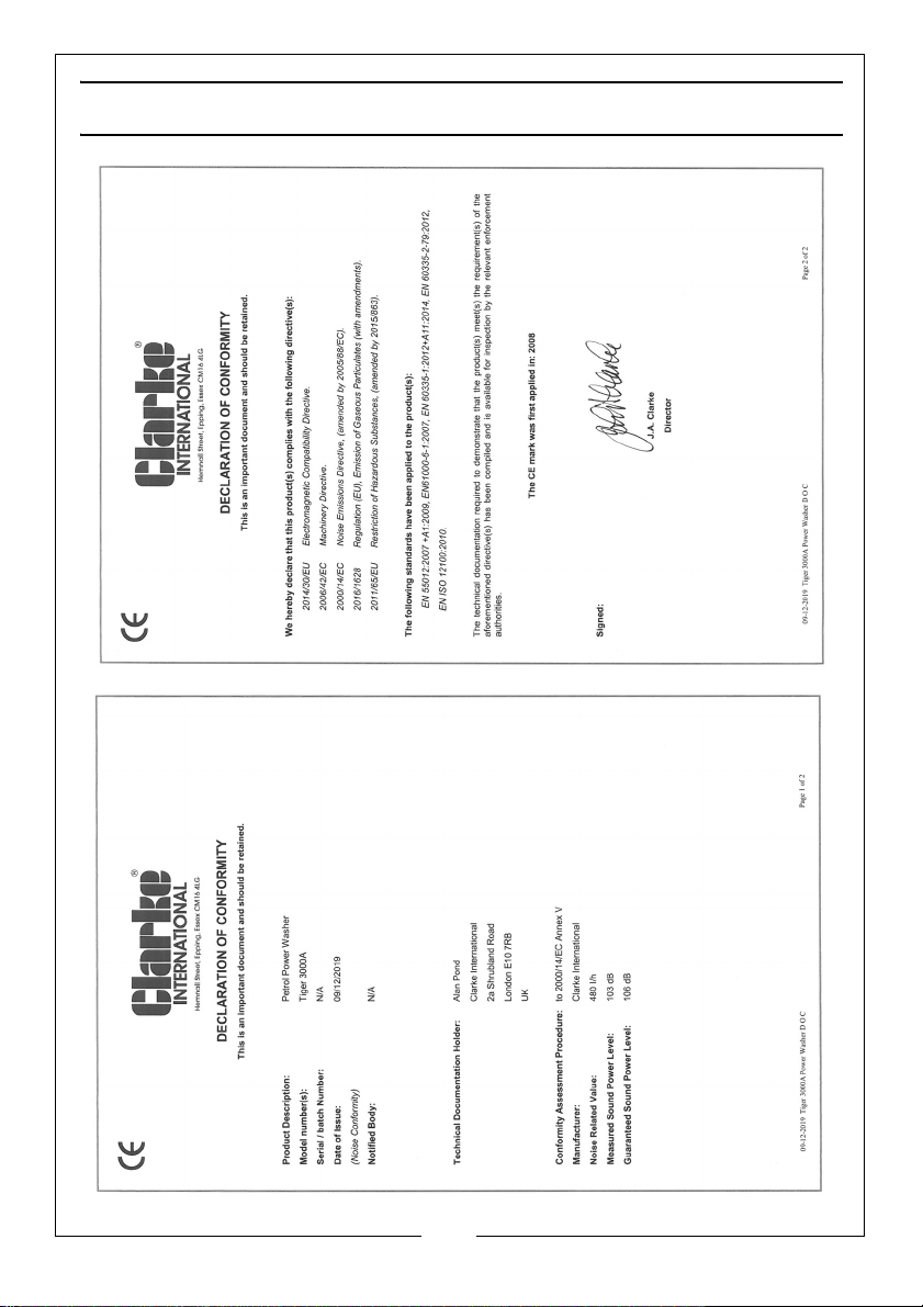
DECLARATION OF CONFORMITY
27
Parts & Service: 020 8988 7400 / E-mail: [email protected] or [email protected]
Page 28

 Loading...