

Page 1
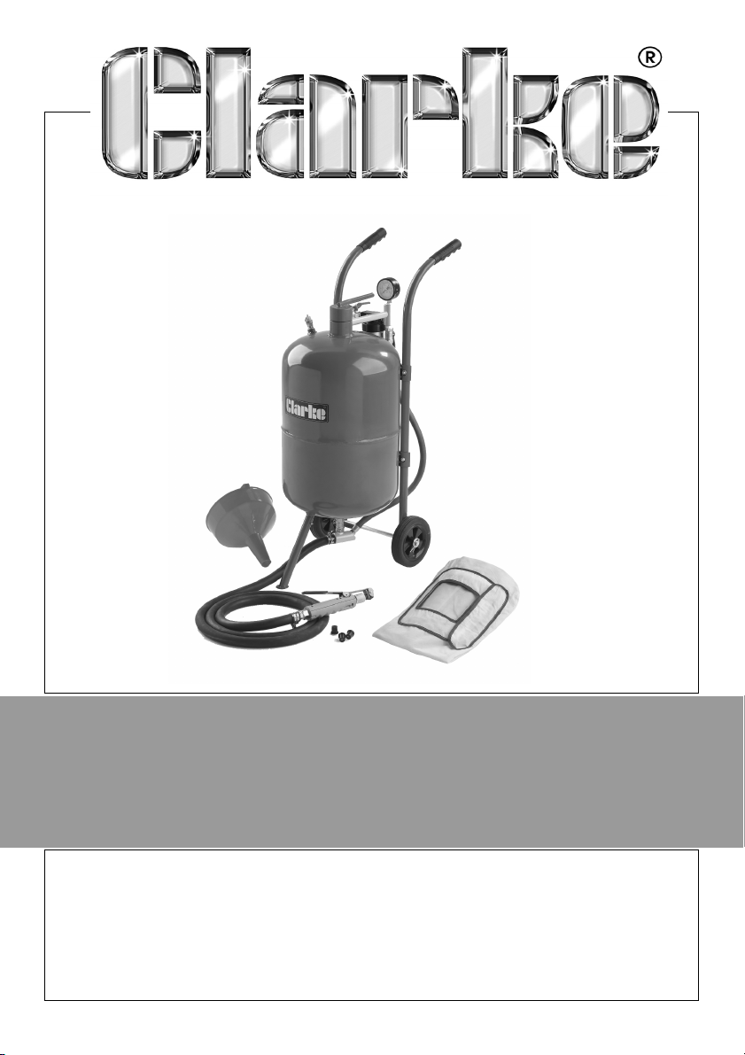
PRESSURISED SANDBLASTER
MODEL NO: CPSB100
PART NO: 7640130
OPERATION & MAINTENANCE
INSTRUCTIONS
ORIGINAL INSTRUCTIONS
LS0917 iss 4
Page 2
INTRODUCTION
Thank you for purchasing this Clarke Pressurised Sandblaster.
Before you try to use this product, read this manual and follow the instructions
carefully. In doing so you will ensure your safety and the safety of others
around you. You can also look forward to a purchase that gives you long and
satisfactory service.
GUARANTEE
This product is guaranteed against faulty manufacture for a period of 12
months from the date of purchase. Please keep your receipt which will be
required as proof of purchase.
This guarantee is invalid if the product is found to have been abused or
tampered with in any way, or not used for the purpose for which it was
intended.
Faulty goods should be returned to their place of purchase, no product can
be returned to us without prior permission.
This guarantee does not effect your statutory rights.
CONSUMABLES
Please be aware that certain parts of this sandblaster will wear, and require
replacing and that these parts may not be covered by your guarantee.
The speed at which certain parts wear depends on the abrasiveness of the
materials used. Replacement parts are available from your nearest Clarke
International dealer.
WHAT IS SUPPLIED
• 1 x Abrasive Tank Assembly
• 2 x Handlebars (with screws, washers and nuts)
• 2 x Wheels and Accessories
• 1 x Wheel Axle
•1 x Sand Hose
• 1 x Funnel
•1 x Hood
• 4 x Nozzle (2mm, 2.5mm, 3mm and 3.5mm)
• 1 x Instruction Manual
2
Page 3

CONTENTS
INTRODUCTION ...................................................................2
GUARANTEE ........................................................................2
CONSUMABLES ...................................................................2
WHAT IS SUPPLIED ...............................................................2
CONTENTS ...........................................................................3
GENERAL SAFETY RULES .....................................................4
ASSEMBLY ............................................................................6
FIT HANDLE BARS TO THE TANK ...............................................6
ASSEMBLE THE FRAME ..............................................................6
ATTACH FRONT LEG .................................................................7
ATTACH THE HOSE ....................................................................7
OPERATION .........................................................................8
SAFETY AND HEALTH CONSIDERATIONS ................................8
ABRASIVE SELECTION ...............................................................8
LOADING THE ABRASIVE ..........................................................9
ABRASIVE FLOW ADJUSTMENT ................................................9
TO START BLASTING ................................................................10
TO STOP BLASTING .................................................................11
RELEASING PRESSURE FROM THE TANK ................................11
MAINTENANCE ..................................................................12
AIR FILTER ................................................................................12
REPLACING THE NOZZLE ........................................................13
SPECIFICATIONS ................................................................14
PARTS & SERVICING ..........................................................14
EXPLODED DIAGRAM & PARTS LIST .................................15
DECLARATION OF CONFORMITY ....................................17
NOTES................................................................................. 18
3
Page 4
GENERAL SAFETY RULES
Warning: Compressed air can be dangerous. Ensure that you are
thoroughly familiar with all precautions relating to the use of
compressors and compressed air supply.
1. Read this instruction manual before connecting the sandblaster to a
compressor.
2. Do not use any silica based abrasives with this tool. Silica based abrasives
have been linked to severe respiratory disease. Always use recommended
abrasives. Abrasives used in this unit may be covered by COSHH
Regulations.
3. Read this manual carefully, Learn the tool's applications and limitations, as
well as potential hazards specific to it.
4. Do not expose tool to moisture. Don't use this tool in damp or wet locations,
Keep out of rain.
5. Keep work area clean and well lit. Cluttered or dark work areas invite
accidents,
6. Keep children away. All children should be kept away from the work area.
Never let a child handle a tool without strict adult supervision.
7. Do not operate this tool if under the influence of alcohol or drugs. Read
warning labels on prescriptions to determine if your judgment or reflexes
are impaired while taking drugs. If there is any doubt, do not attempt to
operate,
8. Use safety equipment. Dust mask, non-skid safety shoes, hard hat, or
hearing protection should be used in appropriate conditions.
9. Don't overreach, Keep proper footing and balance at all times when
operating this product.
10. Always disconnect the tool from the air supply and release pressure from
the tank before storing, servicing, or changing accessories.
11. Use clamps or other practical means to secure and support the work piece
to a stable platform. Do not hold the work by hand or against your body.
12. Do not point the sandblaster at anyone or any objects other than the
intended work object.
13. Check your sandblaster regularly for damage, If part of the sandblaster is
damaged it should be carefully inspected to make sure that it can perform
its intended function correctly. If in doubt, the part should be repaired.
Refer all servicing to a qualified technician. Consult your dealer for advice.
14. Do not attempt to operate this tool near flammable materials or
combustibles. Failure to comply may cause serious injury.
4
Page 5

15. Always check to make sure that the trigger is not on before connecting
blaster to air supply.
16. Store idle tools out of the reach of children and untrained persons. Tools
may be dangerous in the hands of untrained users.
17. Drain water trap periodically during use, Do not allow moisture to fill more
than 1/2 of the water trap bowl. Do not leave water standing in water trap
when storing the sandblaster.
18. Do not allow sandblaster to sit pressurized while unattended or not in use.
19. Periodically check the abrasive medium delivery equipment. Valves, hoses
and nozzles that carry the abrasive medium after it leaves the pressure
tank are subjected to the abrasive blasting action so will wear out more
quickly than other components.
20. Release the air pressure in the tank before opening. See “Releasing
Pressure from the Tank” section, Make sure pressure gauge reads “0”
before opening the tank. Do not attempt any maintenance on the
abrasive blaster until the pressure gauge reads “0”, and it has been
disconnected from the air supply.
21. Maintain correct air pressure whenever working. Do not allow pressure to
exceed 125 psi, If the safety valve does not release excess air pressure, stop
all work and release pressure from the tank (see “Releasing Pressure from
the Tank” section).
22. ALWAYS make sure there is adequate ventilation. Do not spray in confined
areas,
23. In the case of injury seek expert medical advice immediately.
24. SECURE THE WORK Use clamps or a vice to hold the work if it is small or light
weight rather than using your hands. This frees both hands to operate the
nozzle.
5
Page 6
ASSEMBLY
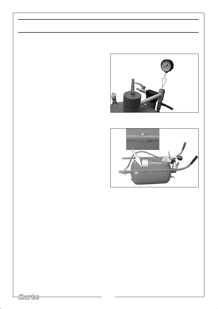
Fig 1
Fig 2
FIT PRESSURE GAUGE TO THE TANK
1.
Screw the pressure gauge onto
the sandblaster as shown in Fig 1.
FIT HANDLE BARS TO THE TANK
1.
Lay the tank on a flat level surface
(such as a workbench or table
top), with the handlebar mounting
brackets facing up, as shown in Fig
2.
• Handlebars are labeled “LEFT”
and “RIGHT.”
2. Align the holes in the left
handlebar with the handlebar
mounting brackets on the left side
of the tank.
3. Place a washer onto each of the four handlebar mounting screws. Insert a
screw through each of the holes in handlebar and mounting brackets,
4. Place a nut onto each of the screws and firmly tighten in place with a
wr
ench.
5. Repeat steps 2-4 for the right
handlebar.
6
Page 7
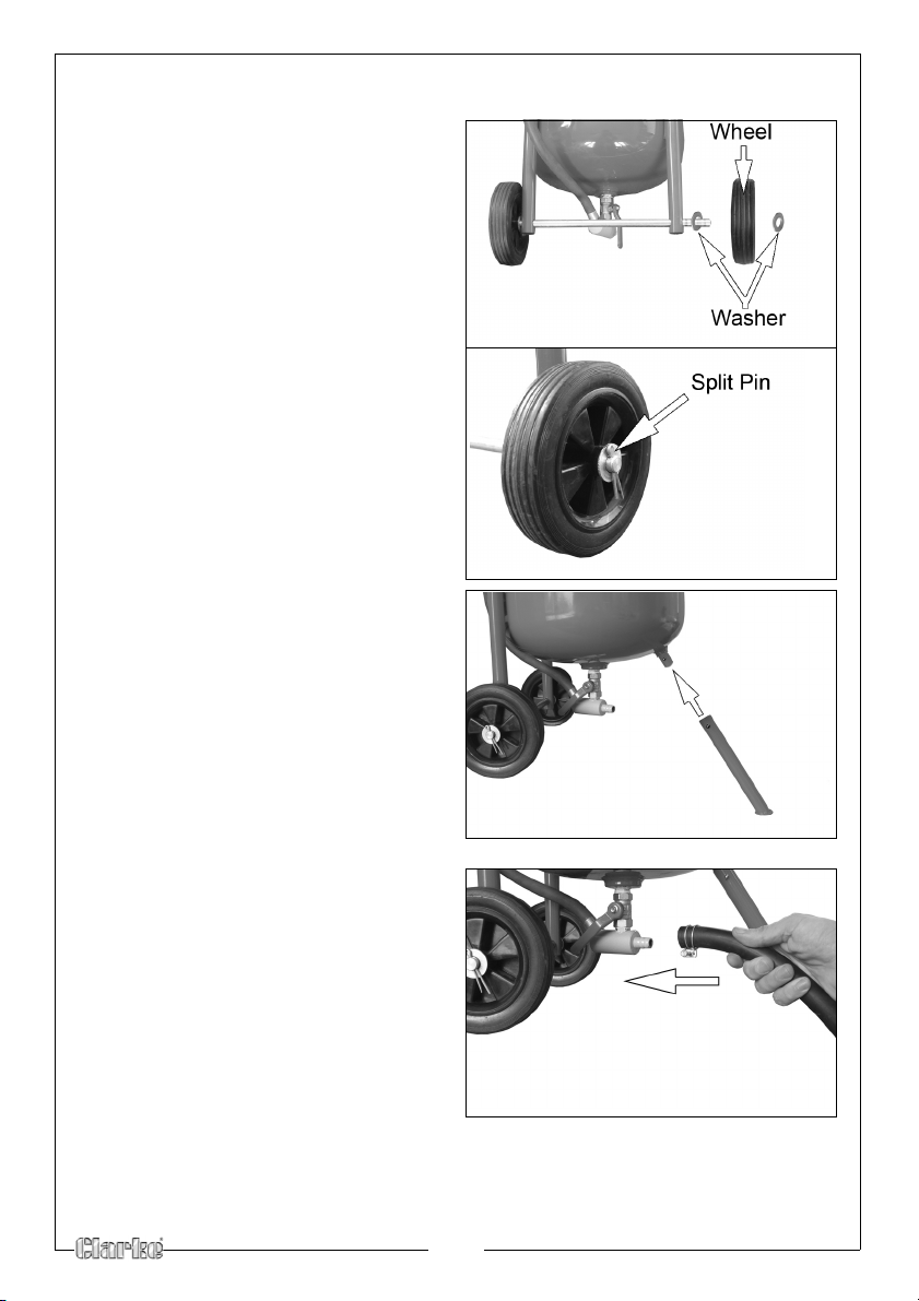
ASSEMBLE THE FRAME
Fig 3
Fig 4
Fig 5
Fig 6
1.
Slide the axle through the axle
holes located at the bottom of
handlebars, see Fig 3.
2. Slide a washer onto each end of
the axle
3.
Place a wheel onto each end of
the axle then slide a washer onto
the axle
4. Insert a split pin through the holes
in each end of the axle and bend
the
off the axle, see Fig 4.
.
.
m so the wheels cannot slide
ATTACH FR ONT LEG
1.
Roll the tank over so that han dlebars
are now facing down.
2. Align the holes of the front foot with
the holes in the foot mount on the
front side of the tank, see Fig 5.
3. Insert a split pin through the holes and
bend it so the front foot ca
slide off the foot mount.
nnot
the
ATTACH THE HOSE
1.
Slide the hose onto the outlet pipe
on the bottom of the sa
as shown in Fig 6.
2. Tighten the clip shown to secure
the hose.
3.Connect the sandblasting gun to
the
other end of the hose, using a
suitable spanner to ensure an air
tight seal.
ndblaster
7
Page 8
OPERATION
WARNING: ALWAYS WEAR YOUR HOOD, DUST MASK AND HEAVY DUTY
CANVAS GLOVES WHEN OPERATING THE SANDBLASTER.
WARNING: BEFORE OPERATING YOUR SANDBLASTER, INSPECT EACH
CONNECTION, DOUBLE CHECKING TO MAKE SURE THAT ALL ARE TIGHT
AND PROPERLY SEALED.
WARNING: THIS SANDBLASTER IS NOT INTENDED FOR USE WITH SILICA BASED
ABRASIVES. WHICH HAVE BEEN LINKED TO SEVERE RESPIRATORY DISEASE.
ALWAYS USE SILICA SUBSTITUTES (SUCH AS CLARKE GLASS BEAD AB RASIVE.
SAFETY AND HEALTH CONSIDERATIONS
• Before opening tank make sure that it is not pressurized. Ensure the
gauge reads “0”. If it does not, release pressure from the tank (See
page 11).
• Disconnect the compressor before opening the tank. Protect
yourself and those around you from “over-spray”. Remember that
your portable abrasive blaster is shooting a powerful spray of
abrasive material. Do not point it at yourself or anyone around you.
• Wear protective clothing including hood (30), and heavy gloves
when using this abrasive blaster.
• Wear a filter or mask over your mouth when using this tool. You will
create a cloud of abrasive material and debris which is dangerous
to inhale.
• Protect anything around you that may be damaged from the
abrasive spray or particles. Nothing subject to contamination
damage or with a fine surface should be near your abrasive
blaster.
ABRASIVE SELECTION
The kind of abrasive you choose will greatly influence the amount of time
needed to clean a given surface area.
8
Page 9
LOADING THE ABRASIVE
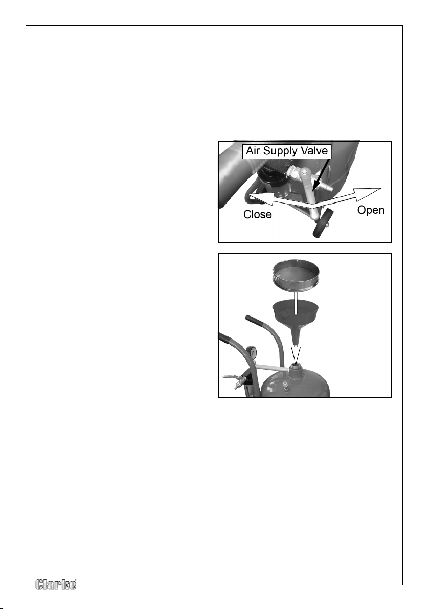
Fig 7
Fig 8
• To prevent clogging, ensure that the abrasive you use is dry.
• While you may re-use abrasive, remember that abrasive grit/
material does wear out. After use, abrasive becomes smoother and
rounder, thus reducing its effectiveness.
NOTE: Re-using abrasive may also cause clogging due to fine debris
contained in the mixture from prior use.
1.
Close the air supply valve by
turning it to the closed position,
see Fig 7
2. Press safety trigger to release any
press
ure from the tank.
• Make sure the pressure gauge
reads “0”
3. Remove the filler cap.
4.
Using the serve and funnel
supplied, pour the selected
abrasive media into the tank, see
Fig 8.
• Do not fill the tank more than ¾
full.
• If humidity in your region is 90%
or more, only fill the tank
and check the water trap more
frequently.
5. Replace the filler cap ensuring the
0-ring
is in place.
NOTE: Place your air compressor in another room to prevent damage
from the intake of abrasive dust laden air.
½ full
ABRASIVE FLOW ADJUSTMENT
• Choose a larger nozzle for a broader spray pattern. Choose a
smaller nozzle for more focused spray.
• Adjust air pressure with the throttle valve. Adjust abrasive flow with
abrasive control valve,
• Watch for abrasive clogging. Release pressure from the tank if
necessary and replace the abrasive with drier or cleaner abrasive.
9
Page 10
TO START BLASTING
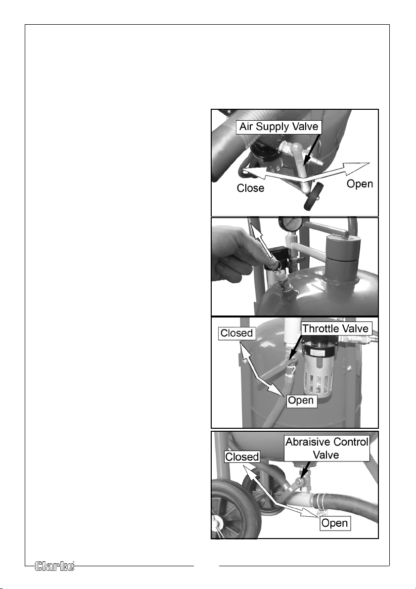
Fig 9
Fig 10
Fig 11
Fig 12
NOTE: Start with all valves in the closed position. Following the instructions
below will help prevent clogging in the delivery hose, outlet
manifold and the safety trigger.
1. Connect compressor to the inlet connector.
2.
Start compressor and open the air
supply valve, see Fig 9.
• The tank will start to pressurise.
Test the safety valve by pulling up
3.
on the valve as shown in Fig 10.
• Air will hiss out when the valve is
pu
lled.
Open the throttle valve, Fig 11.
4.
5. Check for leaks at the filler cap
and along all hoses and fit
the system pressurises. If leaks are
observed, release the pressure
from the tank and repair leaks
immediately.
6. Press and hold the safety trigger
l air is flowing through it.
unti
7.
With the safety trigger open,
slowly open the abrasive control
valve and shown in
abrasive material begins to flow
out of the safety trigger.
8. Adjust the abrasive control valve
until the desired amount of
abrasive material is flowing
through the safety trigger,
9. Begin blasting.
tings as
Fig 12 until
10
Page 11
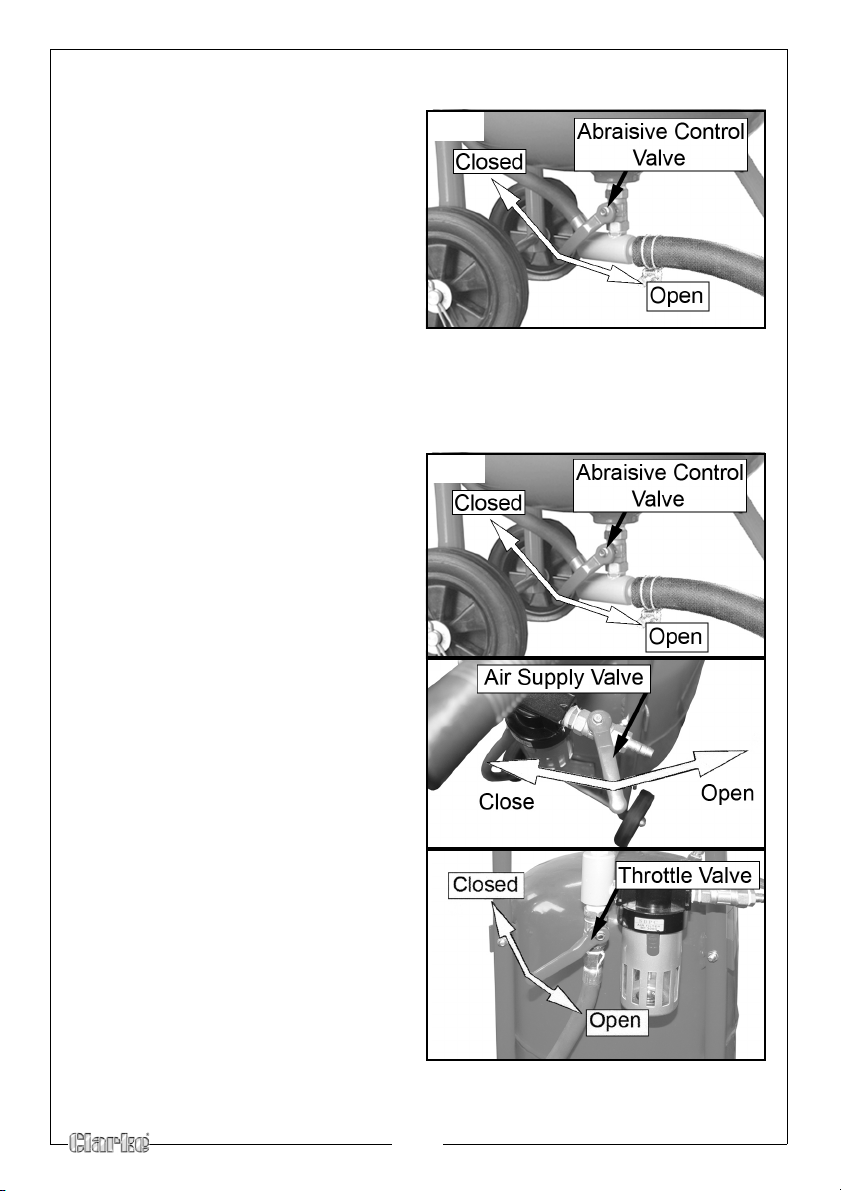
TO STOP BLASTING
Fig 13
Fig 14
Fig 15
Fig 16
1.
While continuing to press and hold
the Trigger, turn the abrasive
rol valve to the closed
cont
position, see Fig 13.
2. When you notice only air (no
abrasive) is coming out of the
safety trigger, you can stop the air
flow by releasing the trigger. By
doing this you are ensuring a
clean and cog-free manifold,
hose, and safety trigger.
3. ALWAYS clean the gun thoroughly after use.
RELEASING PRESSURE FROM THE TANK
1.
When finished blasting, close the
abrasive control valve, see Fig 14.
2. Press and hold the trigger to expel
an
y remaining abrasive material
from the abrasive hose.
3.
When you notice only air (no
abrasive) is coming out of the
safety trigger, Close the Air Supply
Valve, see Fig 15.
4. Ensure the
throttle valve is open,
see Fig 16.
5. Point trigger in a safe direction.
6. Press the trigger until air stops
flowing and pr
essure gauge reads
“0”.
7. Disconnect air supply hose from
supply valve.
11
Page 12
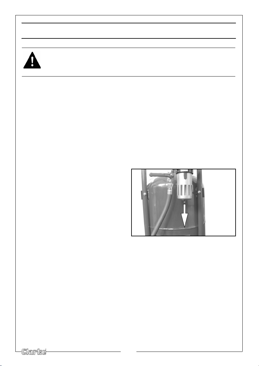
MAINTENANCE
Fig 17
WARNING: DISCONNECT THE SANDBLASTER FROM THE AIR SUPPLY
BEFORE CHANGING ACCESSORIES, ATTEMPTING TO MOVE THE
SANDBLASTER OR PERFORM ANY MAINTENANCE.
1. Keep your sandblaster clean, and protect it from damage.
2. When initially pressurising, check for leaks
hoses and fittings.
3. Leaking joints maybe repa
using teflon tape.
4. Check for worn abrasive hose and fittings,
ired by replacing worn or damaged parts or
AIR FILTER
DRAINING
Condensation will collect in the air filter
1.
Drain the air filter by pulling down
on the drain plug until all the water
comes out, see Fig 17.
at the top of the tank and at all
, which must be drained manually.
12
Page 13
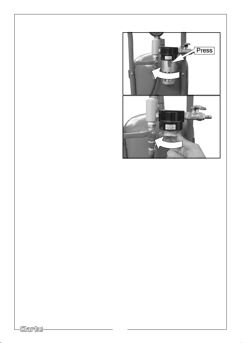
CLEANING/REPLACING
Fig 18
Fig 19
1.
Press the release catch and
unscrew the condensation
chamber, see Fig 18.
Unscrew the filter as shown in Fig
2.
19 and wipe clean.
NOTE: D
o not use harsh or abrasive
chemicals when cleaning
the condensation chamber.
3. Refit the condensation chamber.
REPLACING THE NOZZLE
NOTE: ONLY use identical replacement parts when servicing.
After l0-l2 hours of blasting time the nozzle should be checked for wear. The
nozzle will wear out over time and should be replaced when the hole is no
longer round or the abrasive media does not flow smoothly through. To
replace the nozzle:
1. Disconnect the sandblasting gun from the air hose.
2. Unscrew the nozzle adapter (38),
gun.
3. Remove the old nozzle (37).
4. lnsert new nozzle.
• A pack of 4 Replacement nozzles are available from your Clarke
dealer
5. Replace the nozzle adapter (38) and firmly screw it onto sandblasting gun.
• Keep your sandblaster clean and protect it from damage.
•
Check for worn abrasive hose and fittings. Watch for leaks, blistering,
bulging or thinning of the hose.
• Replace any parts which appear worn.
located at the front of the sandblasting
Part number 7640132.
13
Page 14
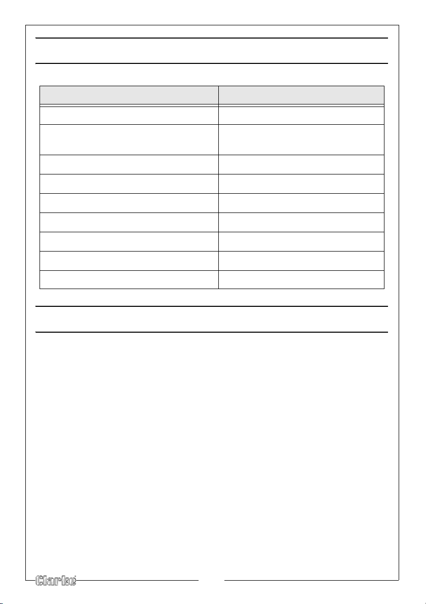
SPECIFICATIONS
CPSB100
Sand Grade Type Above 80 grit
Abrasive Material Aluminium Oxide, Bank Sand,
Beach Sand, Glass
Beads
Tank Capacity (working)
Operating Pressure
Flow Rate Required
Compressor Size
Nozzle Sizes
Dimensions (L x W x H)
Weight (empty) 19 kg
32 Litres (7.04 Gallons)
65 - 125 PSI (4.4 - 8.6 Bar)
6 - 19 CFM (at 115 psi)
2 - 10 HP
2, 2.5, 3, 3.5 mm
440 x 344 x 850 mm
PARTS & SERVICING
For Parts & Servicing, please contact your nearest dealer, or CLARKE
International, on one of the following numbers.
PARTS & SERVICE TEL:
020 8988 7400
PARTS & SERVICE FAX:
020 8558 3622
or e-mail as follows:
PARTS: [email protected]
SERVICE: [email protected]
14
Page 15
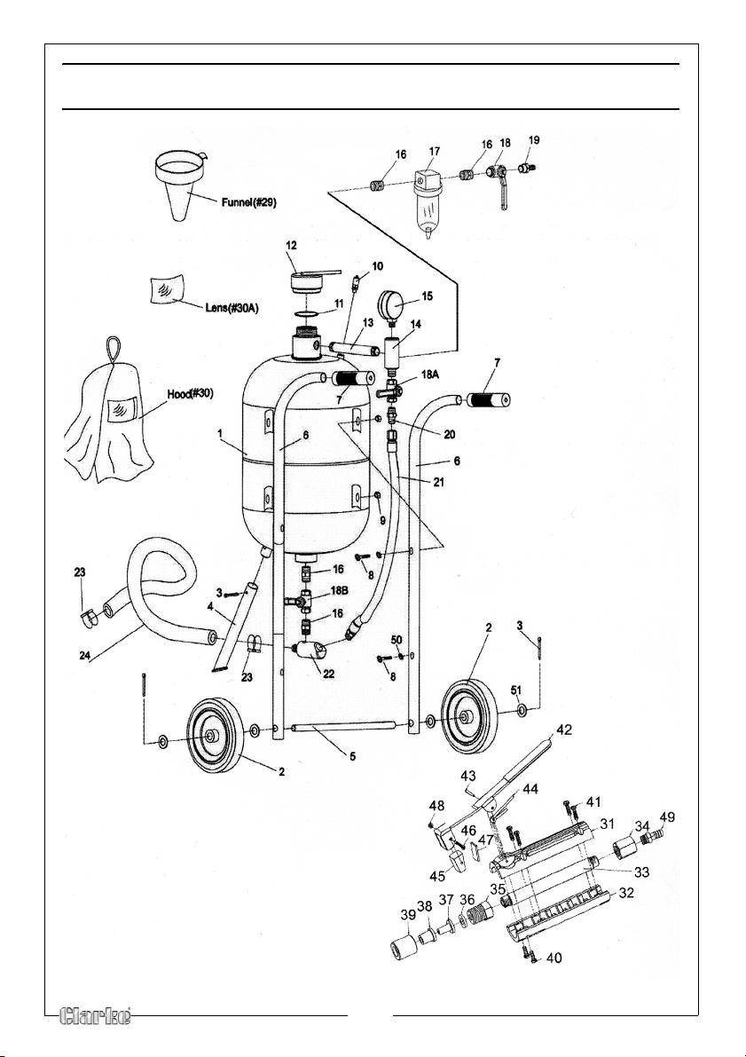
EXPLODED DIAGRAM & PARTS LIST
15
Page 16
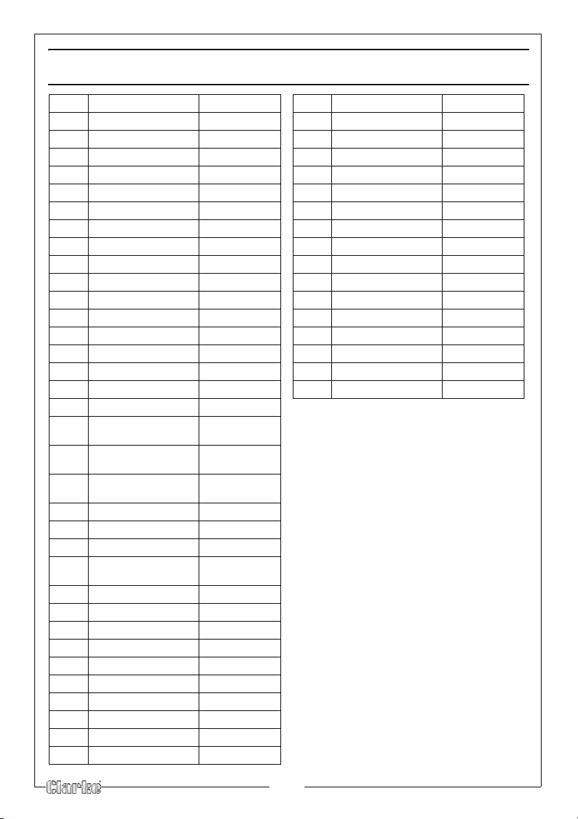
EXPLODED DIAGRAM & PARTS LIST
NO DESCRIPTION PAR T N O
1 Tank HTCPSB10001
2 Wheels HTCPSB10002
3 Cotter Pins HTCPSB10003
4 Front Foot HTCPSB10004
5 Axle HTCPSB10005
6 Handle Bars HTCPSB10006
7 Handle Grips HTCPSB10007
8 Pan Head Screws HTCPSB10008
9 Hex Nuts HTCPSB10009
10 Safety Valve HTCPSB10010
11 0-Ring HTCPSB10011
12 Tank Filler Cap HTCPSB10012
13 Connecting Pipe HTCPSB10013
14 Intake Manifold HTCPSB10014
15 Pressure Gauge HTCPSB10015
16 3/8” Connector HTCPSB10016
17 Water Tr ap Filte r HTCPSB10017
18 3/8” Brass Air Supply
18A 3/8” Brass Throttle
18B 3/8” Steel Abrasive
19 Inlet Connector HTCPSB10019
20 Connector HTCPSB10020
21 Air Hose HTCPSB10021
22 Abrasive Outlet
23 Hose Clamps HTCPSB10023
24 Abrasive Hose HTCPSB10024
29 Funnel HTCPSB10029
30 Hood HTCPSB10030
30A Lens for Hood HTCPSB10030A
31 Upper Body HTCPSB10031
32 Lower Body HTCPSB10032
33 Metal Pipe HTCPSB10033
34 Inlet Connector HTCPSB10034
35 Adapter HTCPSB10035
l ve
Va
Va
l ve
Co
ntrol Valve
Mani
fold
HTCPSB10018
HTCPSB10018A
HTCPSB10018B
HTCPSB10022
NO DESCRIPTION PART NO
36 O-Ring HTCPSB10036
37 Ceramic Nozzle HTCPSB10037
38 Rubber Adapter HTCPSB10038
39 Nozzle Cap Nut HTCPSB10039
40 Screw ST 4.2 x 16 HTCPSB10040
41 Screw ST 4.2 x 12 HTCPSB10041
42 On/Off Control Lever HTCPSB10042
43 Spring Pin HTCPSB10043
44 Spring HTCPSB10044
45 Rubber Pad
46 Screw M3 x 25 HTCPSB10046
47 Hard Alloy Pad HTCPSB10047
48 Nut M3 HTCPSB10048
49 Hose Adapter HTCPSB10049
50 Washer HTCPSB10050
51 Washer HTCPSB10051
HTCPSB10045
16
Page 17
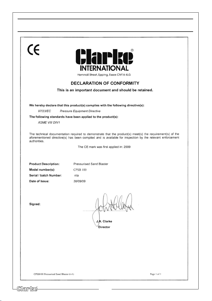
DECLARATION OF CONFORMITY
17
Page 18
NOTES
18
Page 19
NOTES
19
Page 20
 Loading...