

Page 1

2000W VARIABLE SPEED ROUTER
MODEL NO: CR4
PART NO: 6462077
OPERATION & MAINTENANCE
INSTRUCTIONS
ORIGINAL INSTRUCTIONS
GC1018 - ISS1
Page 2

INTRODUCTION
Thank you for purchasing this CLARKE 2000W Variable Speed Router.
The router is designed to be fitted with rotary cutting bits that allows you to cut
slots into or shape the edges of various materials.
Before attempting to use this product, please read this manual thoroughly and
follow the instructions carefully. In doing so you will ensure the safety of yourself
and that of others around you, and you can look forward to your purchase
giving you long and satisfactory service.
GUARANTEE
This product is guaranteed against faulty manufacture for a period of 12
months from the date of purchase. Please keep your receipt which will be
required as proof of purchase.
This guarantee is invalid if the product is found to have been abused or
tampered with in any way, or not used for the purpose for which it was
intended.
Faulty goods should be returned to their place of purchase, no product can
be returned to us without prior permission.
This guarantee does not effect your statutory rights.
ITEMS SUPPLIED
•1 x Router
• 1 x Parallel Fence c/w Guide Rods
• 2 x Fence Rods c/w fixing screws
• 1 x Dust Extraction Port - Internal Ø : 34 mm/external Ø 38mm
• 3 x Collets - 1 x ¼”, 1 x ⅜” and 1 x ½”(fitted)
• 1 x Collet Nut (fitted)
• 1 x Spanner
• 1 x Template Guide Bush 22mm
• 1 x Circle Guide Centre (Trammel Attachment c/w fixings)
• 1 x Roller Guide Assembly
• 1 x Measuring Scale
2
Parts & Service: 020 8988 7400 / E-mail: [email protected] or [email protected]
Page 3
ENVIRONMENTAL RECYCLING POLICY
Through purchase of this product, the customer is taking on the
obligation to deal with the WEEE in accordance with the WEEE
regulations in relation to the treatment, recycling & recovery and
environmentally sound disposal of the WEEE.
In effect, this means that this product must not be disposed of with general
household waste. It must be disposed of according to the laws governing
Waste Electrical and Electronic Equipment (WEEE) at a recognised disposal
facility.
SPECIFICATIONS
Electric Supply 230V 50Hz
Motor Power Rating 2000W
No Load Speed 8000 - 23000 RPM (±10%)
Plunge Range 0 - 66 mm
Collet Size ¼”, ⅜” and ½”
Dust extraction Adaptor Port Size 34 mm I/D / 38 mm O/D
Dimensions: (Length x Height x Width) 155 x 320 x 318 mm
Net Weight 6.25 kg
Sound Pressure level: dB LpA 93 dB
Sound Power level: dB LWA 104 dB (uncertainty factor 3 dBA)
Vibration Levels
Left: 3.184 / right: 4.297m/s
Uncertainty value K (1.5)
2
Specifications are correct at the time of going to print. CLARKE International reserve the
right to change specifications at any time without prior notice.
3
Parts & Service: 020 8988 7400 / E-mail: [email protected] or [email protected]
Page 4

GENERAL SAFETY RULES
1. WORK AREA
a. Keep the work area clean and well lit. Cluttered and dark areas invite
accidents.
b.
Do not operate power tools in explosive atmospheres, such as in the
presence of flammable liquids, gases or dust. Power tools create sparks
which may ignite the dust or fumes.
c.
Keep children and bystanders away while operating a power tool.
Distractions can cause you to lose control.
2. ELECTRICAL SAFETY
a. Power tool plugs must match the outlet. Never modify the plug in any
way. Do not use adapter plugs with earthed (grounded) power tools.
Unmodified plugs and matching outlets will reduce the risk of electric shock.
b.
Do not expose power tools to rain or wet conditions. Water entering a
power tool will increase the risk of electric shock.
c. Do not abuse the cable. Never use the cable for carrying, pulling or
unplugging the power tool. Keep the cable away from heat, oil, sharp
edges or moving parts. Damaged or entangled cables increase the risk
of electric shock.
d. When operating a power tool outdoors, use an extension cable suitable
for outdoor use. Use of a cable suitable for outdoor use reduces the risk of
electric shock.
e. Remove the plug from the socket before carrying out any adjustment,
servicing or maintenance.
f. Fully unwind cable drum extensions to prevent overheating.
g. When an extension cable is required, you must make sure that it has the
right ampere rating for your power tool and is in a safe condition.
3. PERSONAL SAFETY
a. Stay alert, watch what you are doing and use common sense when
operating a power tool. Do not use a power tool while you are tired or under
the influence of drugs, alcohol or medication. A moment of inattention while
operating power tools may result in personal injury.
b.
Use safety equipment. Always wear eye protection. Safety equipment
such as dust mask, non-skid safety shoes, hard hat, or hearing protection used for
appropriate conditions will reduce personal injuries.
Avoid accidental starting. Ensure the switch is in the off position before
c.
plugging in. Carrying power tools with your finger on the switch or plugging in
power tools that have the switch on invites accidents.
4
Parts & Service: 020 8988 7400 / E-mail: [email protected] or [email protected]
Page 5

d. Remove any adjusting key or spanner before turning the power tool on.
A spanner or a key left attached to a rotating part of the power tool may result in
personal injury.
e.
Do not overreach. Keep proper footing and balance at all times. This enables
better control of the power tool in unexpected situations.
f.
Dress properly. Do not wear loose clothing or jewellery. Keep your hair,
clothing and gloves away from moving parts. Loose clothes, jewellery or
long hair can be caught in moving parts.
g. Hold power tool by insulated gripping surfaces, because the cutter may
contact its own cord. Cutting a "live" wire may make exposed metal
parts of the power tool "live" and shock the operator.
h. Use clamps or another practical way to secure and support the
workpiece to a stable platform. Holding the work by your hand or
against the body leaves it unstable and may lead to loss of control.
4. POWER TOOL USE AND CARE
a. Do not force the power tool. Use the correct power tool for your application.
The correct power tool will do the job better and safer at the rate which it was
designed.
b.
Do not use the power tool if the switch does not turn it on and off. Any
power tool that cannot be controlled with the switch is dangerous and must be
repaired.
c.
Disconnect the plug from the power source before making any
adjustments, changing accessories, or storing power tools.
preventive safety measures reduce the risk of starting the power tool
accidentally.
d.
Store idle tools out of the reach of children and do not allow persons
unfamiliar with the power tool or these instructions to operate the power
Power tools are dangerous in the hands of untrained users.
tool.
e. Maintain power tools. Check for misalignment or binding of moving parts,
breakage of parts and any other condition that may affect the power tools
operation. If damaged, have the power tool repaired before use. Many
accidents are caused by poorly maintained power tools.
f.
Keep cutting tools sharp and clean. Well maintained cutting tools with sharp
cutting edges are less likely to bind and are easier to control.
g.
Use the power tool, accessories and tool bits etc, in accordance with
these instructions
could result in a hazardous situation.
. Use of the power tool for operations different from intended
Such
5. SERVICE
a. Have your power tool serviced by a qualified repair person using only
identical replacement parts. This will ensure that the safety of the power tool
is maintained.
5
Parts & Service: 020 8988 7400 / E-mail: [email protected] or [email protected]
Page 6

ADDITIONAL WARNINGS FOR ROUTERS
a. Do not start the router while the bit is touching the workpiece.
b. Make sure that the bit has stopped before engaging the spindle lock.
c. Do not touch the router bits immediately after use - they can be very
hot.
d. Make sure that the plunge spring is always fitted when using hand-held.
e. Only use router bits designed for woodwork and suitable for the speed
rating of this router.
f. Only use bits with a shank diameter exactly matched to the collet(s)
supplied with this router.
g. Extra precautions must be taken when using bits with a diameter
greater then 2" (50mm). Use very slow feed rates and/or multiple
shallow cuts to prevent the motor from overloading.
h. Always examine walls, floors and ceilings for hidden power cables and
pipes.
i. After long work periods external metal parts & accessories can be hot.
j. Handle router bits carefully, they can be extremely sharp.
k. Examine the bit carefully for signs of damage or cracks before use.
Replace damaged or cracked bits immediately.
l. Always use both handles and make sure that you have a firm grip on
the router before starting work.
m. Keep your hands away from the bit.
n. Before using the tool, switch on and let it run for a while. Look for
vibration or wobbling that could indicate an improperly installed bit.
o. Note the direction of rotation of the bit and the direction of feed.
p. Always switch off and wait until the bit has stopped before removing
the router from the work piece and also before putting the router down
on the workbench.
q. Make sure that you have removed foreign objects such as nails and
screws from the workpiece before starting.
6
Parts & Service: 020 8988 7400 / E-mail: [email protected] or [email protected]
Page 7
ELECTRICAL CONNECTIONS
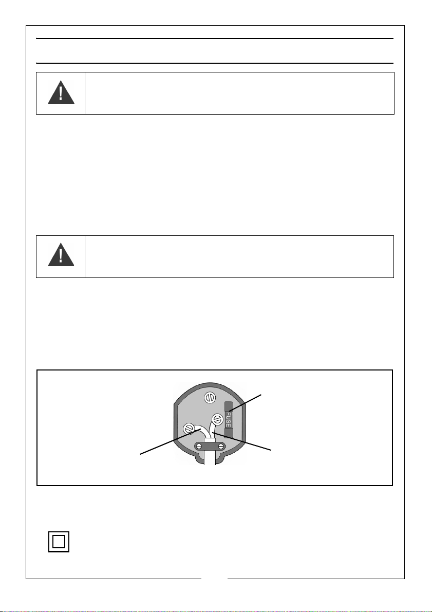
Plug must be BS1363/A approved.
Always fit a 13 Amp fuse.
Ensure that the outer sheath of the cable is firmly held by the clamp
Neutral
(Blue)
Live
(Brown)
WARNING: READ THESE ELECTRICAL SAFETY INSTRUCTIONS
THOROUGHLY BEFORE CONNECTING THE PRODUCT TO THE MAINS
SUPPLY.
Before switching the product on, make sure that the voltage of your electricity supply is
the same as that indicated on the rating plate. This product is designed to operate on
230VAC 50Hz. Connecting it to any other power source may cause damage.
This product may be fitted with a non-rewireable plug. If it is necessary to change the
fuse in the plug, the fuse cover must be refitted. If the fuse cover becomes lost or
damaged, the plug must not be used until a suitable replacement is obtained.
If the plug has to be changed because it is not suitable for your socket, or due to
damage, it should be cut off and a replacement fitted, following the wiring instructions
shown below. The old plug must be disposed of safely, as insertion into a mains socket
could cause an electrical hazard.
WARNING: THE WIRES IN THE POWER CABLE OF THIS PRODUCT ARE
COLOURED IN ACCORDANCE WITH THE FOLLOWING CODE:
BLUE = NEUTRAL BROWN = LIVE
If the colours of the wires in the power cable of this product do not correspond with the
markings on the terminals of your plug, proceed as follows.
• The wire which is coloured Blue must be connected to the terminal which is
marked N or coloured Black.
• The wire which is coloured Brown must be connected to the terminal which is
marked L or coloured Red.
We strongly recommend that this machine is connected to the mains supply via a Residual
Current Device (RCD)
This symbol indicates that this is a Class II product, and does
not require an earth connection.
Parts & Service: 020 8988 7400 / E-mail: [email protected] or [email protected]
7
Page 8
Page 9

OVERVIEW
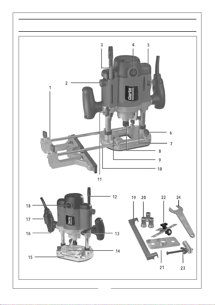
DESCRIPTION DESCRIPTION
1 Parallel Guide 13 Plunge Locking Lever
2 Depth Adjusting Knob 14 Dust Extractor Port
3 Depth Stop Scale 15 Base Plate
4 Brush Access Cover 16 Safety Button
5 Speed Control 17 Trigger
6 Side fence locks 18 Brush Access Cover
7 Spindle Lock 19 Width Measuring Scale
8 Collet Retaining Nut 20 Collets
9 Depth Stop Turret 21 Template Guide Bush
10 Guide Rod 22 Circle Guide Assembly
11 Depth Stop Locking Knob 23 Trammel Attachment
12 Fine Depth Adjuster 24 Spanner
9
Parts & Service: 020 8988 7400 / E-mail: [email protected] or [email protected]
Page 10
BEFORE USE
INSTALLING AND REMOVING A ROUTER BIT
WARNING: MAKE SURE THAT THE ROUTER IS ISOLATED FROM POWER
SUPPLY BEFORE YOU CHANGE THE BIT.
WARNING: MAKE SURE THAT YOU USE THE RIGHT SIZE COLLET FOR THE BIT
BEING USED.
WARNING: ONLY USE ROUTER BITS THAT HAVE A SPEED RATING THAT
EXCEEDS THE MAXIMUM SPEED OF THIS ROUTER.
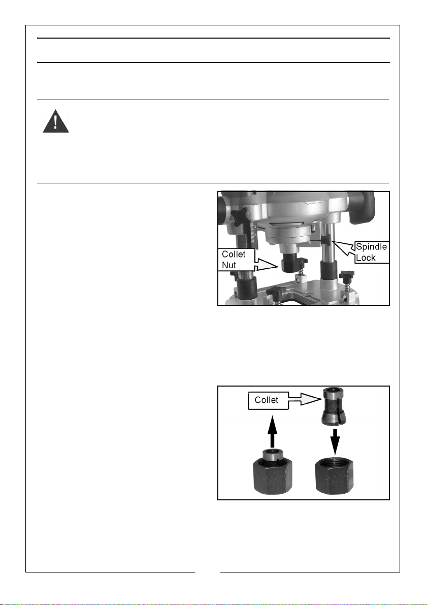
1. Push and hold the spindle lock.
2. Turn the spindle until the spindle
locks into position.
3. Use the spanner supplied to
loosen the collet nut and remove
the bit if one is installed.
4. Slide a bit into the spindle and
tighten the collet nut.
NOTE: At least ¾ of the shank must
be inside the collet.
• Do not tighten the collet nut without a bit installed.
5. Release the spindle lock.
CHANGE THE COLLET SIZE
1. Push and hold the spindle lock.
2. Turn the spindle until it locks into
position.
3. Loosen the collet nut using the
spanner supplied.
4. Carefully remove the collet from
the nut and replace with the
collet you need.
• Your router is supplied with 3
collets, ¼”, ⅜” and ½”.
5. Replace the nut.
10
Parts & Service: 020 8988 7400 / E-mail: [email protected] or [email protected]
Page 11
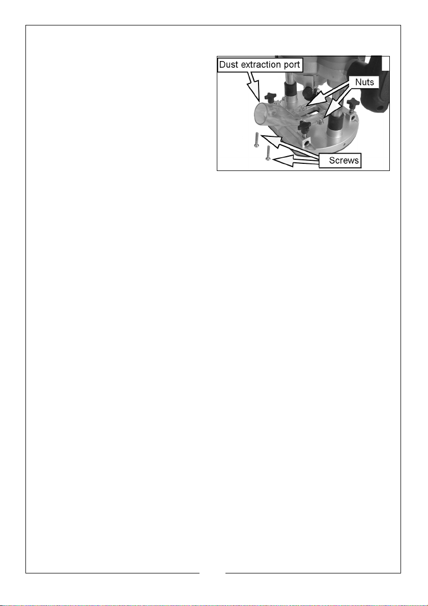
INSTALL AND REMOVE THE DUST EXTRACTION PORT
1. Fit the dust extraction port to the
router as shown using the screws
and nuts supplied.
2. Sit nuts in the sockets on the dust
extraction port and insert the
screws from underneath.
• The dust extraction port has an
internal diameter of 34 mm.
11
Parts & Service: 020 8988 7400 / E-mail: [email protected] or [email protected]
Page 12
OPERATION
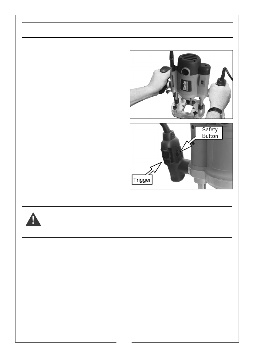
CORRECT HAND POSITION
The correct way to hold the router is
as shown.
SWITCHING ON/OFF
1. Grip the router with both hands,
making sure that the handle with
the trigger is in the right hand.
2. Push and hold the safety button
and squeeze the trigger.
• Let the motor reach full speed
before use.
• To stop the router, release the
trigger.
WARNING: THE CUTTER WILL CONTINUE TO TURN BRIEFLY AFTER THE
TRIGGER IS RELEASED.
12
Parts & Service: 020 8988 7400 / E-mail: [email protected] or [email protected]
Page 13
ADJUSTING THE DEPTH OF CUT
CAUTION: TO PREVENT DAMAGE TO THE MOTOR OR DIFFICULTY
CONTROLLING THE TOOL, THE DEPTH OF CUT SHOULD BE LIMITED TO 5-6
MM IN EACH PASS. IF YOU REQUIRE MORE THAN THIS MAKE MULTIPLE
CUTS WITH GRADUALLY DEEPER SETTINGS.
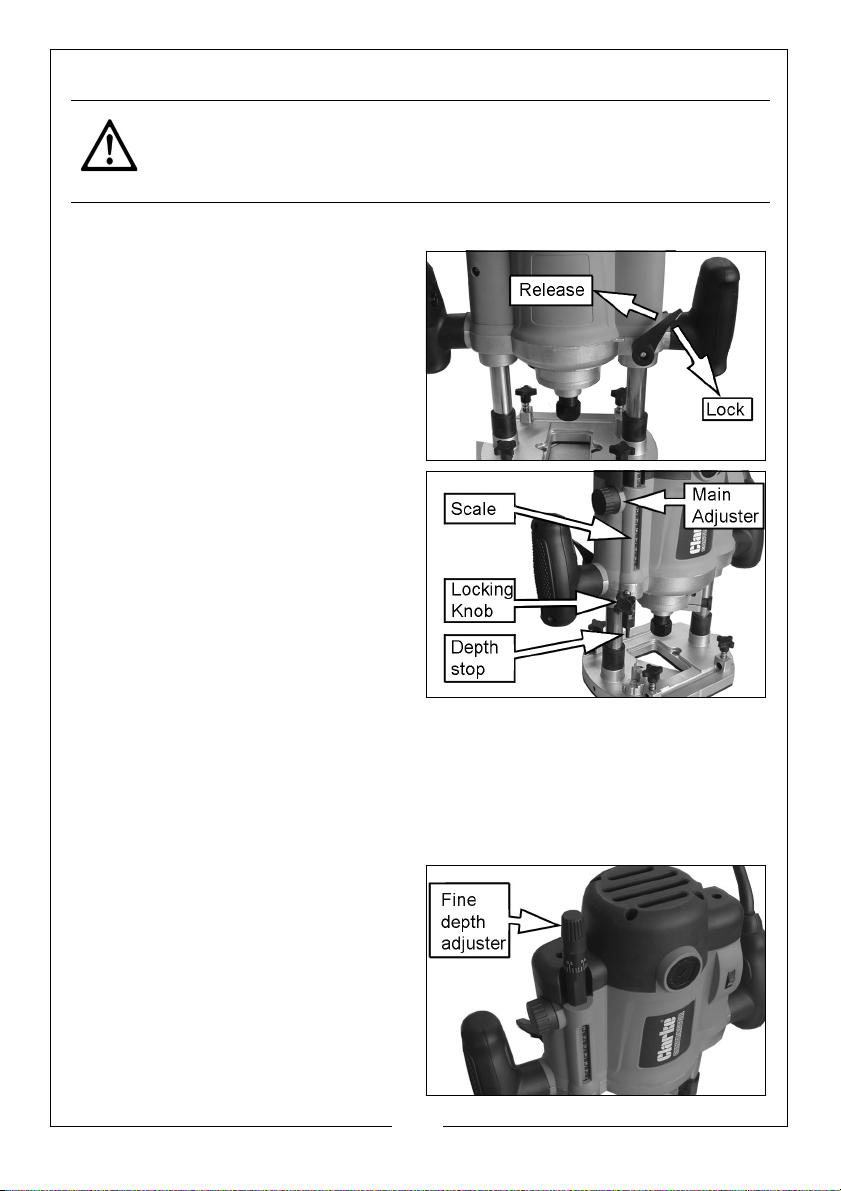
1. Install the cutter into the router and put the router on a flat surface.
2. Release the plunge lock lever and
lower the router body until the bit
just touches the surface, then
apply the plunge lock to lock the
router in position.
3. Slacken the depth stop locking
knob and lower the depth stop
until the rod touches the turret at
its lowest setting.
• Rotate the turret if needed.
4. Twist the main adjuster and the
fine depth adjuster until the scale
for each one reads zero. This is
your starting point.
5. Turn the knob to raise the height
of the main depth stop by the depth you want to cut into the workpiece.
• The scale is marked in mm.
6. Tighten the depth stop locking knob to secure the setting.
USING THE FINE DEPTH ADJUSTER
1. Make fine adjustments by twisting
the fine depth adjuster.
• This is calibrated in 0.2 mm
increments
• Twisting clockwise will drive the
stop rod towards the turret
stop, reducing the depth of
plunge.
13
Parts & Service: 020 8988 7400 / E-mail: [email protected] or [email protected]
Page 14
USING THE MULTI-STOP TURRET
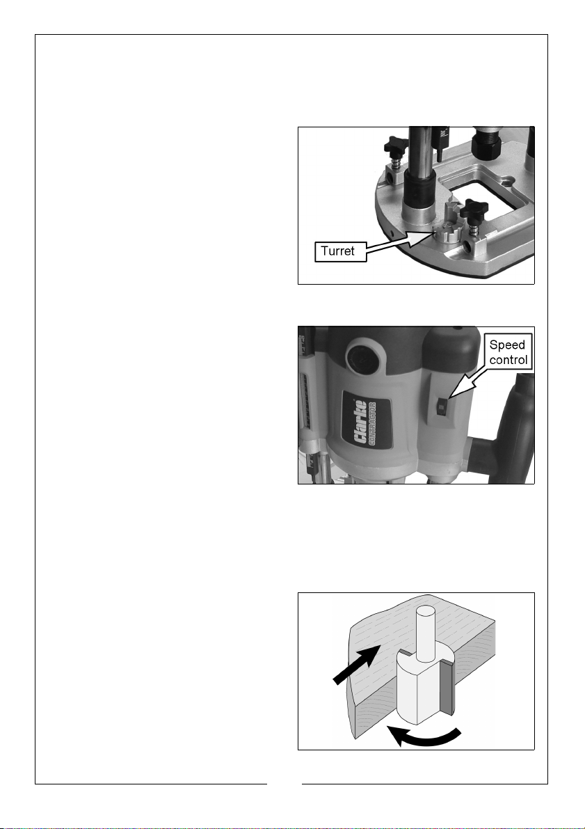
The multi-stop turret can be used to assist in making multiple passes. Using the
turret in this manner removes the necessity for resetting the depth stop for
each pass. Each stop on the turret is approximately 3 mm.
1. With the total depth set and the
router raised fully, turn the turret to
its highest position.
2. Make the first pass across the
wood.
3. Rotate the turret to a lower setting
and make the second pass.
4. Repeat this until the final cut is
made.
CHANGING THE SPINDLE SPEED
The router speed is infinitely variable
from 8000 to 23000 rpm.
1. Turn the speed control to the
required setting.
• Generally, the larger the
diameter of the bit, the slower
the tool speed should be
• The correct setting will also
depend on the density of the
material being cut, the feed
speed and the depth of cut.
2. It is advisable to make practice cuts on a piece of scrap timber to
determine the best speed as a large loss of RPM will overload the motor.
FEED DIRECTION
Remember that the direction the bit
is fed into the wood must always be
against the direction of rotation as
shown in the diagram on the right.
This ensures a quality finish and also
ensures that the cutting action pulls
the router into the wood.
14
Parts & Service: 020 8988 7400 / E-mail: [email protected] or [email protected]
Page 15
FEED SPEED
The speed at which the router is moved along the workpiece must not be so
fast that it causes the motor to slow down, or so slowly that the bit starts to
leave burn marks on the timber.
The proper feed rate to use depends on the bit size, the material being cut,
the depth of the cut and the speed selected.
Practice judging the feed speed on scrap timber by listening to the router
during use.
MOULDING NATURAL TIMBERS
Always route the end grain of natural timber first. This will ensure that any
breakout is removed when the long grain is routed.
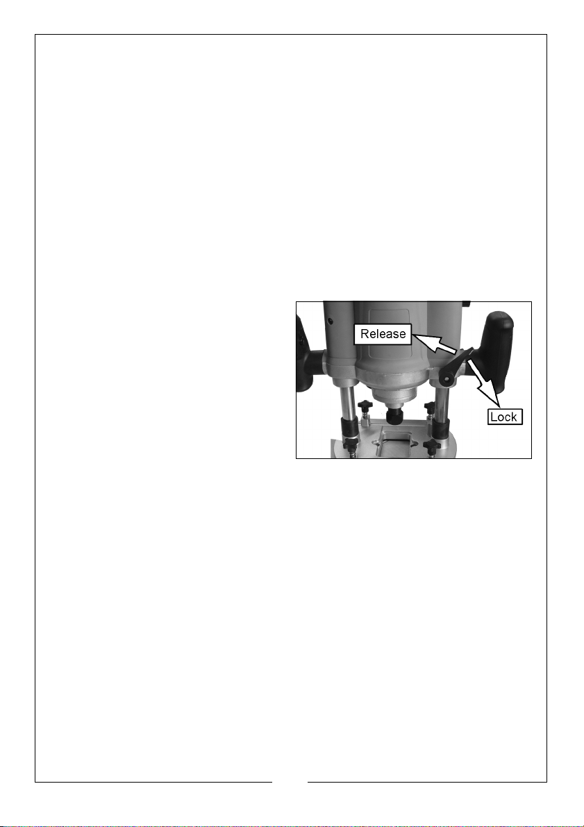
PLUNGE CUTTING
1. Set the required depth of cut. See
page 13.
2. With the motor running, press
down on the two handles to
plunge the cutter into the wood.
3. Depress the plunge locking lever
to lock the motor carriage in
position.
4. Carry out the routing operation.
5. Release the plunge locking lever to return the motor carriage to its normal
position.
15
Parts & Service: 020 8988 7400 / E-mail: [email protected] or [email protected]
Page 16
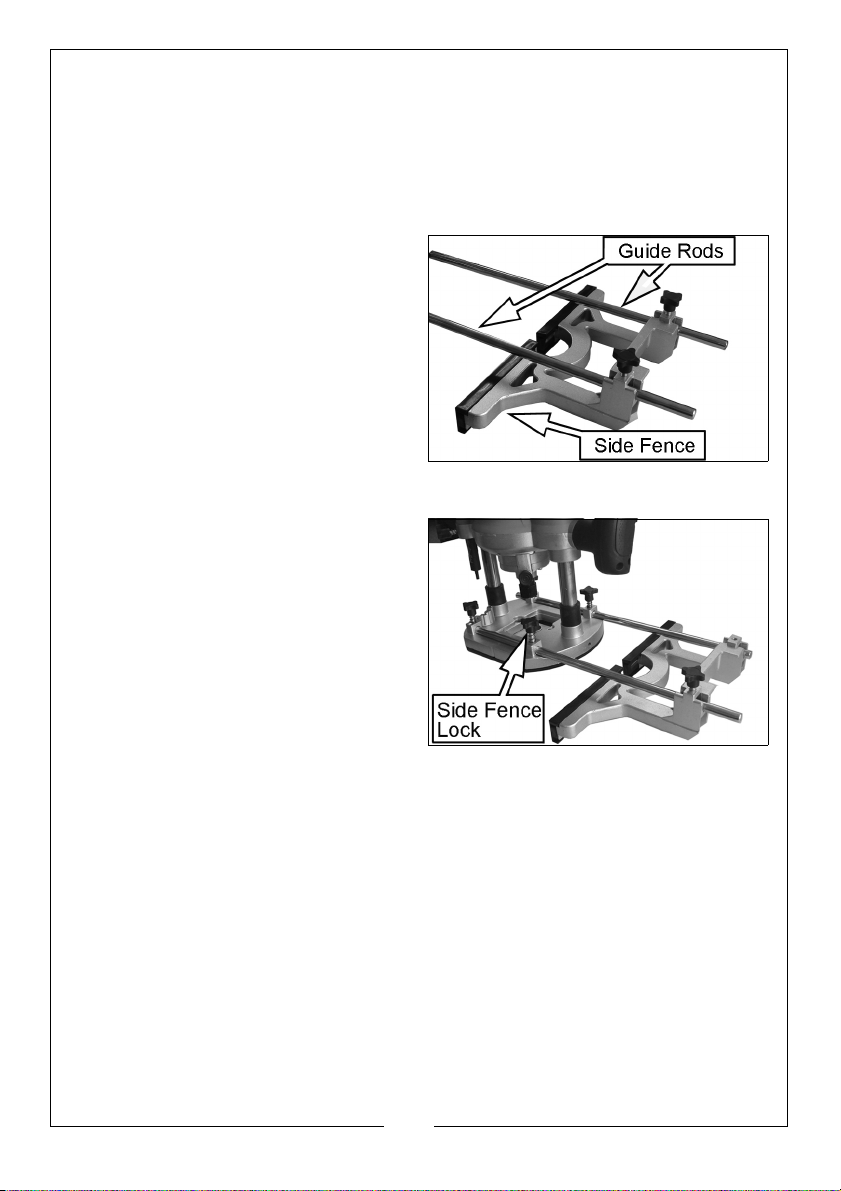
SIDE FENCE ROUTING
The side-fence is used to guide the router when routing grooves and slots
parallel to the workpiece edge.
• The edge of the workpiece must be straight and true.
FITTING THE SIDE FENCE
1. Fit the guide rods to the side
fence and secure using the
screws, washers and spring
washers supplied.
2. Make sure that the side fence
locks are fully loosened.
3. Slide the guide rods into the router
base.
4. Tighten the side fence locks.
USING THE SIDE FENCE
1. Adjust the side-fence as required
and lock in place using the side
fence locks.
2. Set the depth of cut, see page 13.
3. When the router reaches full
speed, gently lower the cutter into
the workpiece and lock the
plunge lever.
4. Move the router along the
workpiece, maintaining a
sideways pressure to ensure the side fence does not come away from the
workpiece and downward pressure on the inside hand to prevent the
router from tipping over.
NOTE: When starting the cut, increase the pressure slightly on the front of the
side fence and as you reach the end of the workpiece increase the
pressure on the rear half on the side fence, this will prevent the router
cutter from ‘snatching’ around the workpiece
5. When finished, release the plunge lever to raise the router and switch off.
16
Parts & Service: 020 8988 7400 / E-mail: [email protected] or [email protected]
Page 17
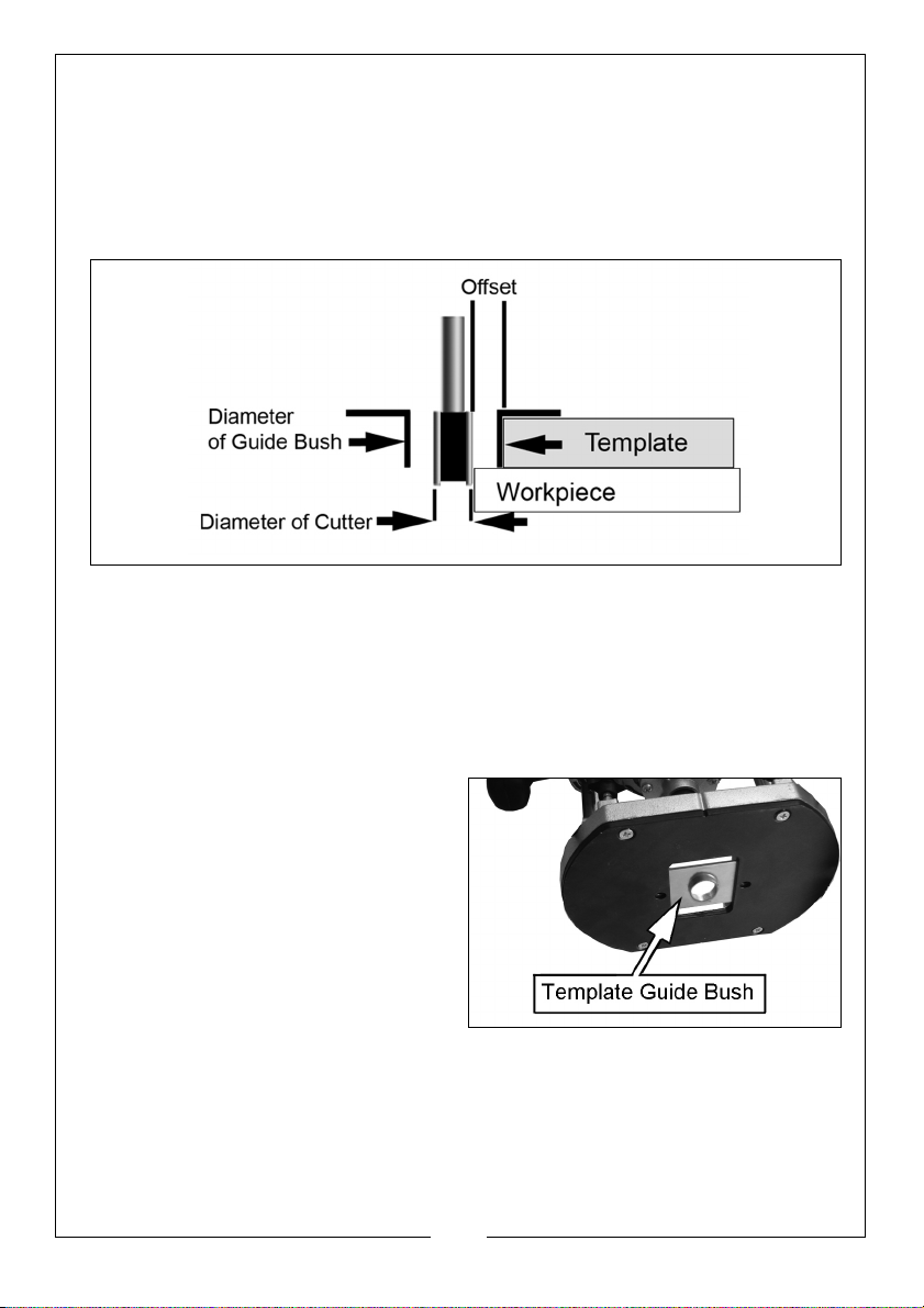
MAKING A TEMPLATE
Router templates must have a minimum thickness of 6 mm and can be home
made or shop bought.
When making templates, you must remember to allow for the distance from
the edge of the guide bush to the edge of the bit, this is known as the offset.
CALCULATIONS FOR THE TEMPLATE OFFSET
The offset is calculated as follows:
• (The outer diameter of the guide bush minus (-) the diameter of the
cutter) divided by 2.
For example, if you use the supplied 22 mm guide bush and a 12 mm router
cutter the offset would be 5 mm.
USING THE TEMPLATE GUIDE BUSH
The Guide Bush Plate should be used
when template/jig cutting.
1. Remove the dust extraction port
(14) by first removing the two bolts
and nuts that secure it.
2. Remove the protective plastic
pad from underneath the base
plate by removing the four screws
that secure it.
3. On the internal side of the plastic
pad fit the Guide Bush Plate into the recess with the bush (circular flange)
facing downwards below the router.
4. Refit the plastic pad with the four screws.
5. Refit the dust extraction port.
17
Parts & Service: 020 8988 7400 / E-mail: [email protected] or [email protected]
Page 18
6. Fit the router bit at the correct height position suitable for the template or
jig to be used.
7. Make the cut as required carefully following the template or jig pattern.
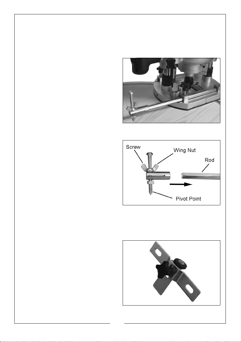
FITTING THE CIRCLE GUIDE (TRAMMEL)
The Circle Guide allows accurate
circles and arcs to be cut.
1. Slide a guide rod into the sockets
in the top of the base plate.
2. Tighten the guide rod locking
knobs to secure the rod.
3. Fit the Circle Guide onto the end
of the guide rod with the point
facing downwards so that it is
positioned on the correct side of
the router for the cut that you intend to make.
4. Assemble the screw and wing nut
on the Circle Guide as shown.
5. Adjust the screw and wing nut
until the pivot point on the screw is
touching the workpiece.
6. Ensure the Circle Guide assembly
is held securely on the guide rod
by tightening the screw or wing
nut.
7. Adjust the guide rod position in
the router base to achieve the required length (radius) from the anchor
position to the centre of router bit.
USING THE ROLLER GUIDE
The Roller Guide attaches to the
parallel guide. It enables the router to
follow the curved shape of the wood.
18
Parts & Service: 020 8988 7400 / E-mail: [email protected] or [email protected]
Page 19
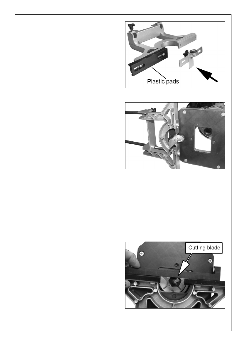
1. Remove the two plastic pads from
the parallel guide by removing
the four screws.
2. Attach the Roller Guide using two
of the screws to the two inner
threaded holes of the parallel
guide.
• The Roller Guide wheel should
face away from the parallel
guide, so that the wheel faces
the cutter.
3. Attach the parallel guide fitted
with the Roller Guide to the router
using both guide rods, and secure
using the guide rod locking knobs.
4. Adjust the distance between the
router bit and roller by loosening
the guide rod locking knob on
each side and positioning the
Roller Guide at the correct
distance. Tighten the Knobs to set
the position.
5. Adjust the Roller Guide height if required using the wing nut.
6. To use, hold the router securely with both hands and make the cut by
allowing the Roller Guide to follow the outline shape of the wood. This can
be used for curved workpieces.
NOTE: Ensure the Roller Guide wheel is kept clean and rotates freely.
Lubricate with a suitable PTFE spray if necessary.
USING THE WIDTH MEASURING SCALE
1. With your chosen router bit fitted,
press down on the router so that
the bit protrudes below the base
plate. Lock the router in that
position.
2. Slide the parallel guide assembly
forward until the working face of
the guide is in line with the cutting
edge of the bit.
3. Rotate the bit so that one of the
two cutting blades is in line with the face of the guide.
19
Parts & Service: 020 8988 7400 / E-mail: [email protected] or [email protected]
Page 20
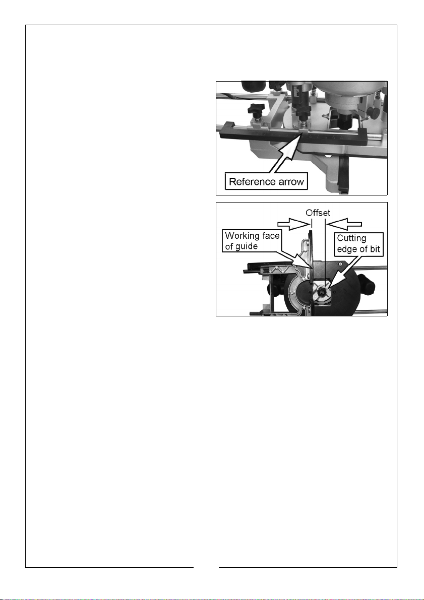
4. Use the scale as a straight edge to confirm this.
5. When correct, lock the parallel guide in that position with the
thumbscrews.
6. Clip the reference scale to the
guide rod, noting that there is a
reference mark (arrow) at the
location shown on the base.
7. Release both guide rods and slide
the guide assembly away from
the router, noting that the scale
shows the distance that the guide
moves away from the cutting bit.
• This will be the maximum offset
distance between the cutting
side of router bit and the
parallel guide touching the
edge of the workpiece.
REPLACEMENT ROUTER BITS
Replacement bits are available from your Clarke dealer as follows:
CHT362:- 15 piece router bit set ¼” shank - Part No 1801362
CHT363:- 15 piece router bit set ½” shank - Part No 1801363
20
Parts & Service: 020 8988 7400 / E-mail: [email protected] or [email protected]
Page 21

MAINTENANCE AND CARE
GENERAL INSPECTION
Make sure that all nuts, bolts and screws are tight and secure.
Always have any damaged or worn parts repaired or replaced.
Always have your router repaired by qualified service personnel. Do not
attempt to repair the router unless you are qualified to do so.
CLEANING
Keep your router clean at all times. Dirt and dust will cause internal parts to
wear quickly and shorten the machine’s service life.
Clean the body of your machine with a soft brush or dry cloth.
Never use caustic agents to clean plastic parts. If dry cleaning is not sufficient,
a mild detergent on a damp cloth is recommended. Water must never come
into contact with the machine.
If available, use clean, dry, compressed air to blow dust away from the routers
moving parts.
Keep the cooling vents on the motor housing unobstructed at all times. Blow
out any dust and dirt at regular intervals with compressed air if available.
MOTOR BRUSHES
Over time the carbon brushes inside the motor may become worn. Excessively
worn brushes may cause loss of power, intermittent failure or visible sparking.
To replace the brushes, remove the two brush access covers. Remove the
worn brushes and ensure the sockets are clean. Carefully replace with new
brushes and then replace the brush access covers.
After fitting, run the router without load for 2-3 minutes to help the brushes bed
in. The process of the brushes fully bedding in may take repeated uses. Motor
sparking may continue until new carbon brushes have bedded in
Alternatively, have the machine serviced at an authorised service centre.
LUBRICATION
The bearings of this router are sealed for life and require no maintenance.
STORAGE
Make sure that the router has been thoroughly cleaned before storing it in a
clean, dry place out of the reach of children.
21
Parts & Service: 020 8988 7400 / E-mail: [email protected] or [email protected]
Page 22
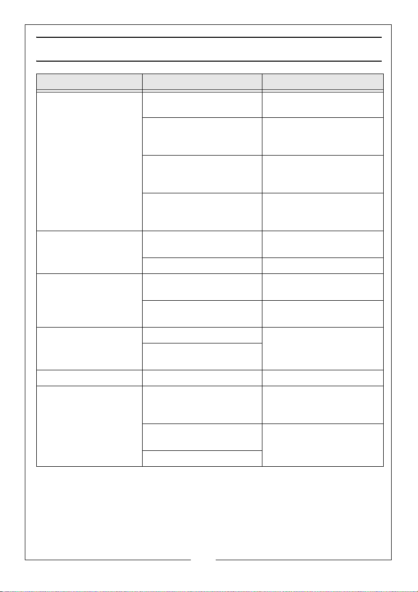
TROUBLESHOOTING
Problem Reason Solution
Router will not operate. No supply of power Check that power is
available at source
Brushes worn or sticking Replace as described on
page 21 or request your
dealer to replace.
Switch is faulty Contact the CLARKE
service department (0208
988 7400)
Motor components open
or short circuited
Router runs slowly. Variable speed set low Increase variable speed
Motor is overloaded Reduce pressure on router.
Router is overheating. Ventilation holes are
blocked / machine is dirty.
Router is overloaded. Do not use put excessive
Makes an unusual
sound.
Excessive vibration. Bent cutter shank Replace cutter
Heavy sparking occurs
inside motor housing.
Mechanical obstruction Contact the CLARKE
Armature has shorted
sections
Brushes not moving freely Disconnect power,
Armature short circuited
or open circuited
Commutator dirty
Contact the CLARKE
service department (0208
988 7400)
setting.
Make sure the ventilation
holes are clear.
pressure on the cutter.
service department (0208
988 7400)
remove brushes, clean or
replace
Contact the CLARKE
service department (0208
988 7400)
22
Parts & Service: 020 8988 7400 / E-mail: [email protected] or [email protected]
Page 23
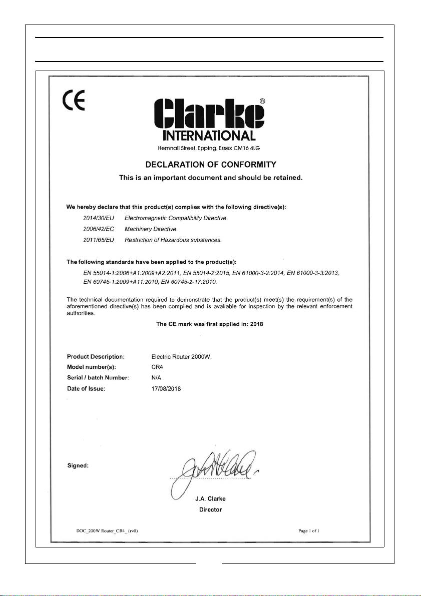
DECLARATION OF CONFORMITY
23
Parts & Service: 020 8988 7400 / E-mail: [email protected] or [email protected]
Page 24

 Loading...