

Page 1
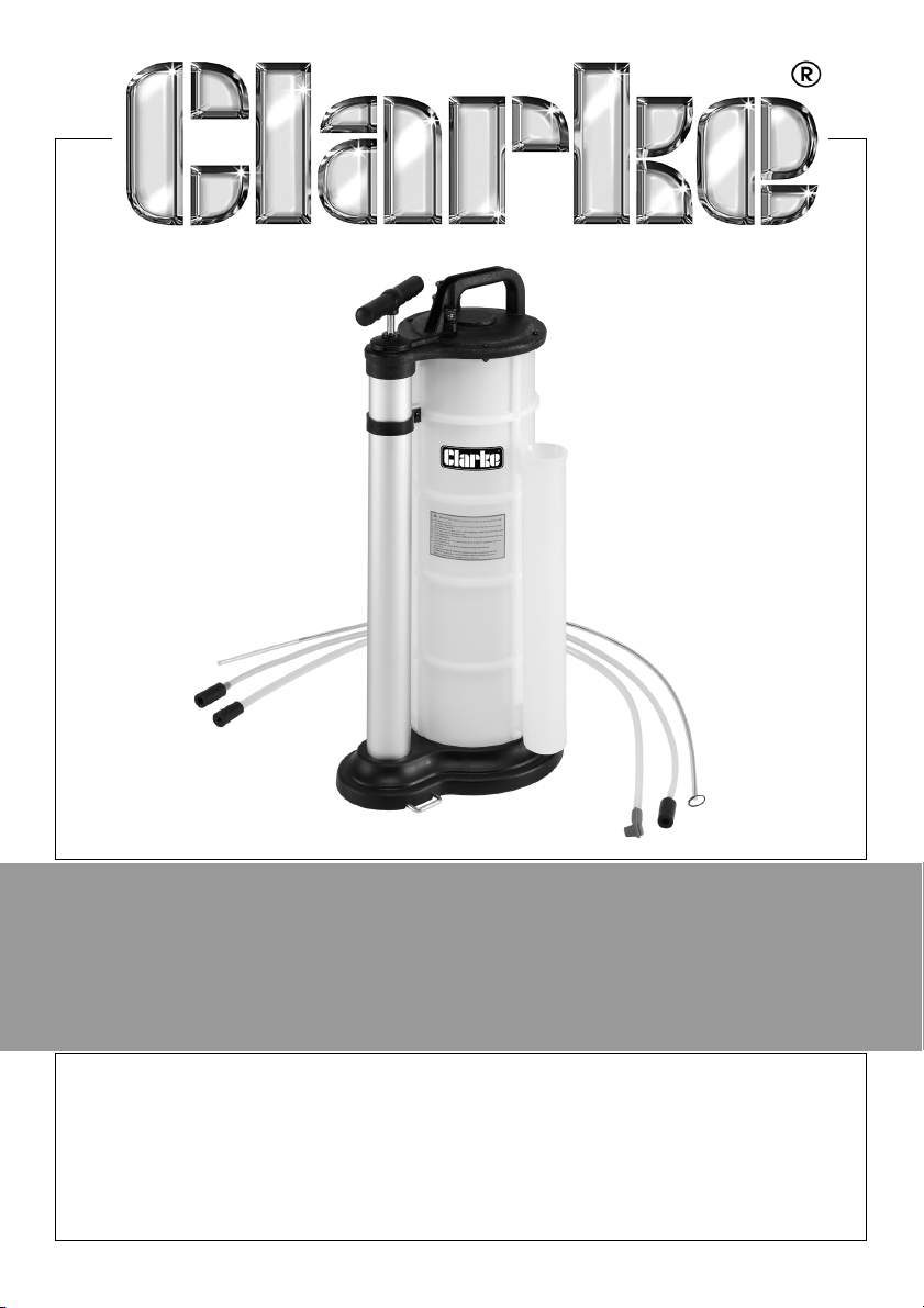
9L OIL / FLUID EXTRACTOR
MODEL NO: CHT928
PART NO: 1801928
OPERATION & MAINTENANCE
INSTRUCTIONS
LS1020ORIGINAL INSTRUCTIONS
Page 2
INTRODUCTION
Thank you for purchasing this CLARKE 9L Oil / Fluid Extractor.
This product is suitable for extracting Water, Oils and liquids, Motor Oil, Brake
Fluid, Antifreeze,
THIS PRODUCT IS NOT SUITABLE FOR EXTRACTING, PETROL OR DIESEL
Before attempting to use this product, please read this manual thoroughly and
follow the instructions carefully. In doing so you will ensure the safety of yourself
and that of others around you, and you can look forward to your purchase
giving you long and satisfactory service.
GUARANTEE
This product is guaranteed against faulty manufacture for a period of 12
months from the date of purchase. Please keep your receipt which will be
required as proof of purchase.
This guarantee is invalid if the product is found to have been abused or
tampered with in any way, or not used for the purpose for which it was
intended.
Faulty goods should be returned to their place of purchase, no product can
be returned to us without prior permission.
This guarantee does not effect your statutory rights.
SAFETY SYMBOLS
Refer to instruction
manual Wear protective gloves
Wear eye protection Wear protective mask
2
Parts & Service: 020 8988 7400 / E-mail: [email protected] or [email protected]
Page 3
SAFETY WARNINGS
WARNING: MAKE SURE THAT HEALTH & SAFETY, LOCAL AUTHORITY, AND
GENERAL WORKSHOP PRACTICE REGULATIONS ARE STRICTLY ADHERED
TO WHEN USING THIS EQUIPMENT.
IMPORTANT: Make sure that you
wear protective clothing, gloves,
goggles, face mask as
appropriate for the fluid being
extracted.
1. Keep the extractor clean and
maintain it in good condition.
2. Replace or repair damaged
parts. Use genuine CLARKE parts
only. Unauthorised parts may be
dangerous and will invalidate the
warranty.
3. Check extractor connections
and fittings before use. Check
that there are no leaks.
4. Ensure that the extractors tank
capacity exceeds the amount of
fluid to be collected.
5. Make sure that the end of the
suction tube is fully submerged in
the fluid before operating.
6. When not in use, store in a safe,
dry, childproof area.
7. Keep the work area clean,
uncluttered and ensure there is
adequate lighting.
8. Maintain correct balance and
footing. Ensure the floor is not
slippery and wear non-slip shoes.
9. Keep children and unauthorised
persons away from the working
area.
10. Dispose of waste fluids in
accordance with local authority
regulations. DO NOT ALLOW
UNCONTROLLED DISCHARGE OF
FLUIDS, THUS POLLUTING THE
ENVIRONMENT.
11. DO NOT pull or yank any pipes or
hoses and do not attempt to
move the extractor by pulling the
hose.
12. Use only to extract engine or
transmission oils, or similar NONcorrosive fluids. The unit may also
be used for the transfer of water.
13. DO NOT use to extract hazardous
or harmful chemicals, solvents,
petrol, diesel, kerosene, alkaline
or acids. If such fluids are used in
the unit, it must be immediately
drained and thoroughly cleaned.
Use with prohibited fluids will
invalidate your warranty.
14. DO NOT store fluids in the
extractor. Fluids must be emptied
into an approved receptacle as
soon as possible.
15. DO NOT dismantle, tamper or
adapt the extractor for any
purpose other than for which it is
designed.
16. DO NOT store in areas of high
temperature, direct sunlight, rain
or snow.
3
Parts & Service: 020 8988 7400 / E-mail: [email protected] or [email protected]
Page 4
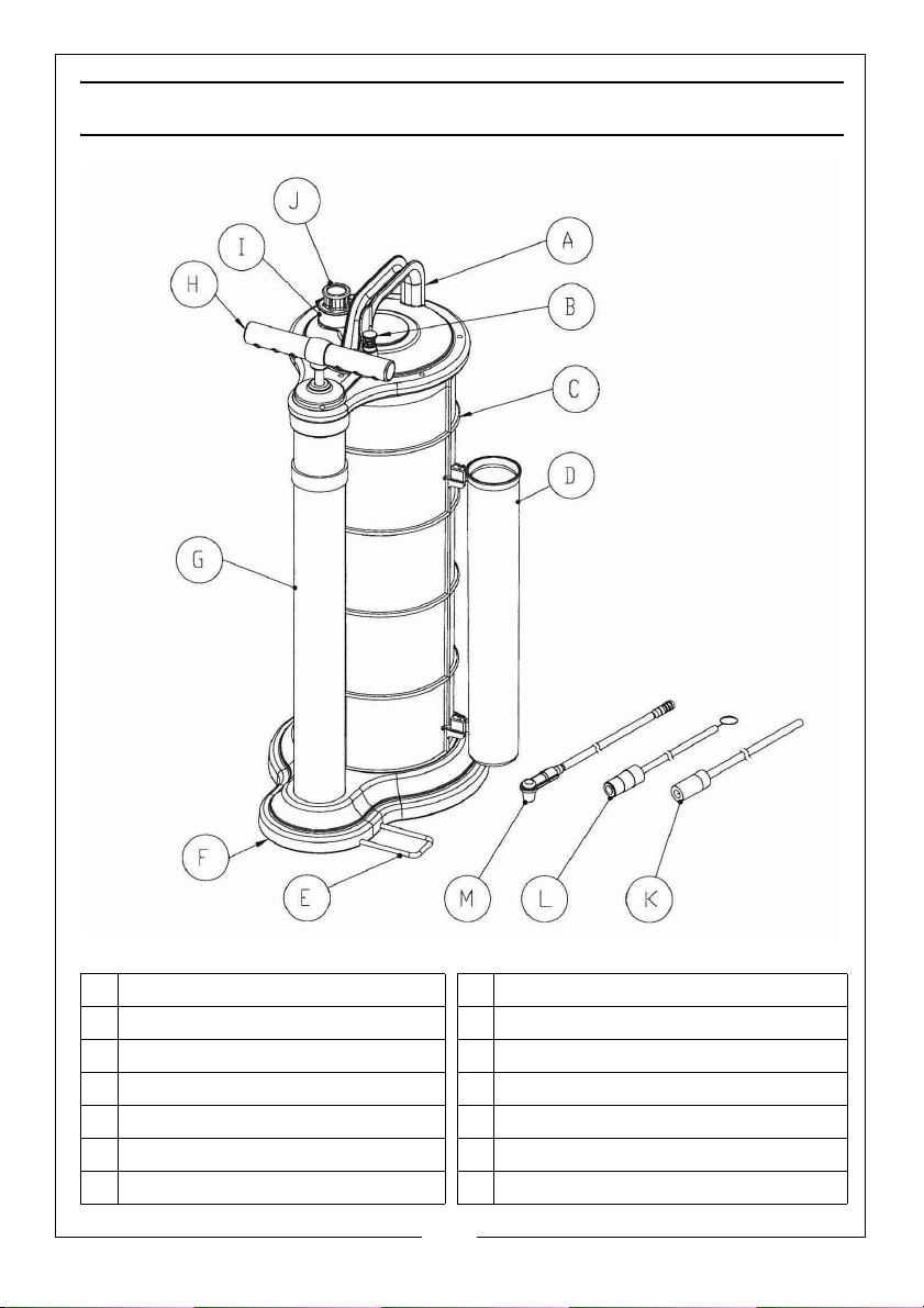
PART IDENTIFICATION
A Housing Cover H Pump Handle
B Release Button I Fluid Outlet Housing
C Tank J Fluid Inlet Coupler
D Tube Storage Unit K Suction Tube with adaptor
E Foot rest L Extraction Tube with adaptor
F Base M Brake Tube with Rubber Fitting
GHand Pump
4
Parts & Service: 020 8988 7400 / E-mail: [email protected] or [email protected]
Page 5
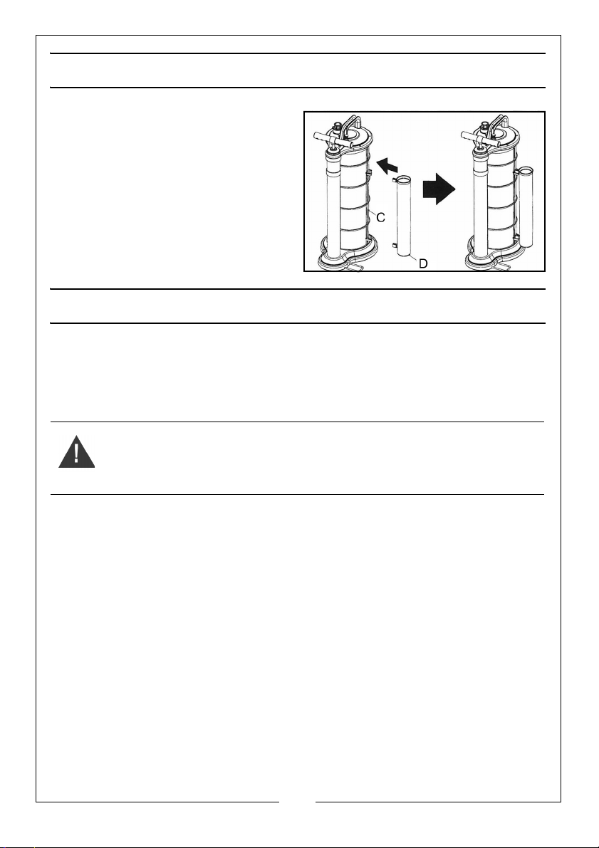
ASSEMBLY
1. Fit the Tube Storage Unit (D) on to
the hooks of the Tank (C) as
shown.
2. Push down until the Tube Storage
Unit (D) snaps into position.
BEFORE USE
When using the fluid extractor to extract engine oil:
• Make sure the vehicle is level.
• Run the engine for 5 minutes to warm the oil and allow any sludge or
contamination within the oil to mix.
WARNING: MAKE SURE THAT THE OIL TEMPERATURE DOES NOT EXCEED
o
C.
70
• Turn off the engine, before using the extractor.
5
Parts & Service: 020 8988 7400 / E-mail: [email protected] or [email protected]
Page 6
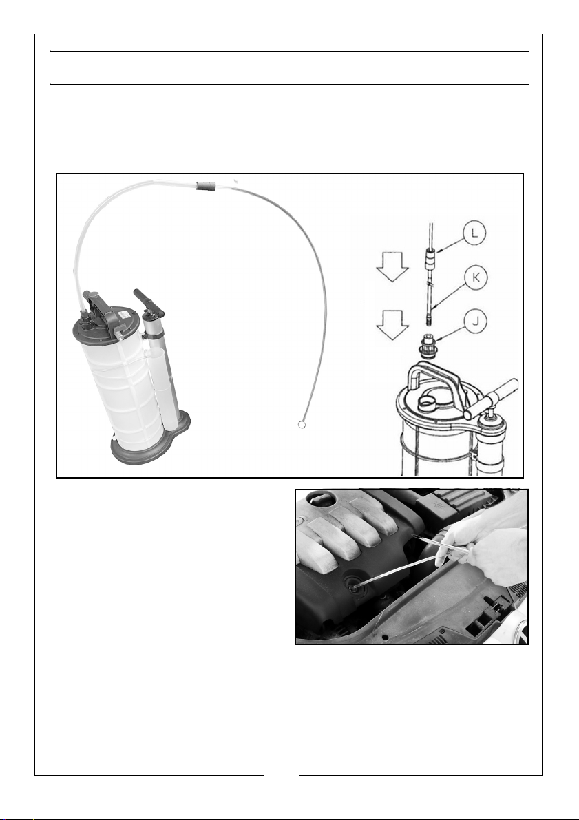
OPERATING INSTRUCTIONS
1. Position the extractor near the engine.
2. Connect the Suction Tube (K) to the Fluid Inlet Coupler (J) with the Suction
Tube Adapter. Connect the other end of the Suction Tube (K) to the
Extraction Tube (L) with the Extraction Tube Adapter.
3. Remove the oil dipstick from the
engine.
4. Put the Extraction Tube (L) into the
dipstick hole until it touches the
bottom of the oil sump.
NOTE: Put the wire supplied into the
extracting tube to keep the
tube rigid if necessary.
6
Parts & Service: 020 8988 7400 / E-mail: [email protected] or [email protected]
Page 7
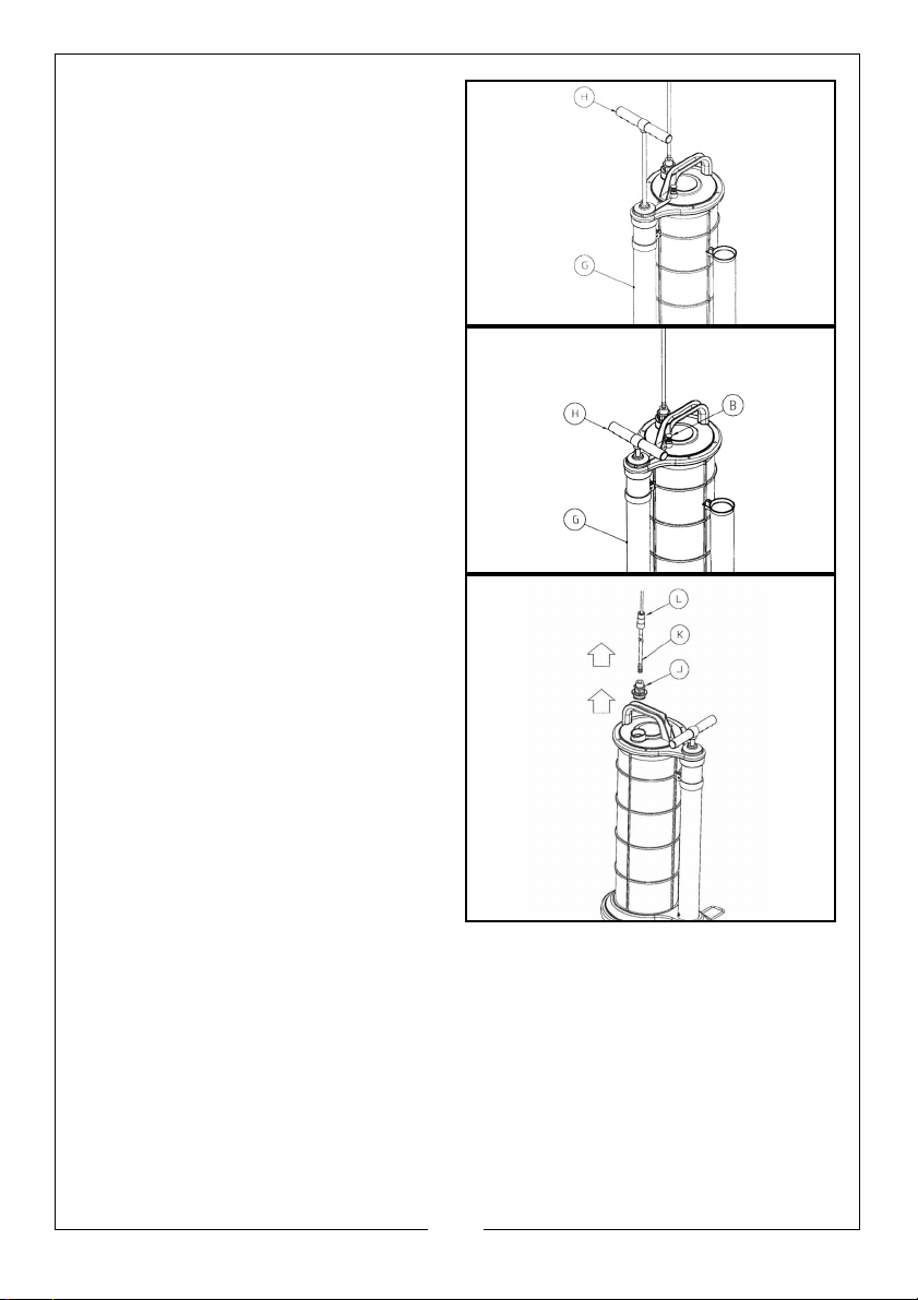
5. Extend the foot rest.
6. Put your foot on the foot rest to
steady the unit.
7. Pump the handle up and down
through its full travel.
• As you pump up and down, the
tank starts to fill.
8. When the tank is full, an auto shut
off mechanism operates and the
pump handle will lock up.
• To return the handle (H) to the
down position hold down the
release valve button (B) at the
top of the pump body and
push the handle down
9. Disconnect the Suction Tube (K)
and the Extracting Tube (L)
removing them from the dipstick
hole.
10. Remove the extractor probe from
the dipstick tube and replace the
dipstick. Disconnect the fluid inlet
coupling from the top of the unit
and pour the extracted fluid into
a suitable container. Discard the
fluid according to local authority
regulations.
7
Parts & Service: 020 8988 7400 / E-mail: [email protected] or [email protected]
Page 8
TROUBLESHOOTING
Cause Remedy
The extractor doesn't suck up
any fluid.
1. Make sure the tube is fully inserted.
2. Has all of the fluid been removed.
3. Make sure that the extractor isn't full.
BRAKE FLUID SAFETY
WARNING: BRAKE FLUID IS FLAMMABLE - KEEP AWAY FROM SOURCES OF
IGNITION, INCLUDING HOT SURFACES E.G. EXHAUST MANIFOLD.
WARNING: BRAKE FLUID WILL DAMAGE PAINT WORK. ANY SPILLAGE
SHOULD BE FLUSHED WITH WATER IMMEDIATELY.
1. Dispose of waste liquids in accordance with local authority regulations.
2. Always read and comply with the warnings on the brake fluid container.
3. Wear eye protection and keep skin contact to a minimum. If brake fluid
enters the eyes rinse with plenty of water and seek medical advice. If
swallowed seek medical advice immediately.
BRAKE BLEEDING
WARNING: FAMILIARISE YOURSELF WITH THE HAZARDS OF BRAKE FLUID READ MANUFACTURERS INSTRUCTIONS ON THE CONTAINER.
NOTE: Do not touch the vehicle’s brake pedal whilst bleeding the brakes with
this extractor.
Refer to the vehicle manufacturers instructions before proceeding. If no
specific instructions exist, follow the instructions detailed below.
1. Remove the brake fluid reservoir lid on the vehicle.
2. Fill the reservoir to its maximum mark.
8
Parts & Service: 020 8988 7400 / E-mail: [email protected] or [email protected]
Page 9
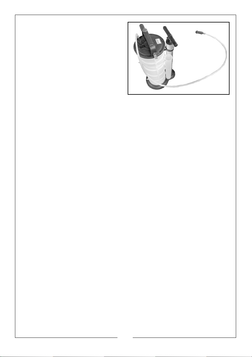
3. Identify the brake bleeding tube
which has a blue flexible plastic
brake nipple connector at one
end and a black rubber adaptor
at the other.
4. Connect the brake bleeding tube
(M) to the top of the fluid
extractor tank by pushing the
black rubber adaptor into the
fluid inlet coupling.
5. Push the blue flexible plastic brake
nipple connector onto the brake nipple on the first wheel and open the
nipple about 1/4 of a turn.
6. Operate the pump. A vacuum will be created which will draw the brake
fluid from the vehicles brake system. Operate the unit for a few seconds
only to avoid draining the vehicles brake fluid reservoir entirely.
IMPORTANT: Check the level of brake fluid in the vehicles reservoir and top
up regularly as required. If possible a reservoir top up device should be
fitted to the brake fluid reservoir.
7. Continue to bleed the system and top up the vehicle reservoir until there
are no air bubbles visible in the clear tube.
8. Close the brake nipple and remove the rubber pipe.
9. Repeat the process at each wheel in turn.
CHANGING THE BRAKE FLUID
1. Repeat the brake bleeding procedure as described until the master
cylinder reservoir is at its minimum level.
2. Fill the reservoir with new brake fluid and continue to bleed the system.
• Check the reservoir level regularly.
3. When new fluid can be seen in the clear tube tighten the brake nipple.
4. Repeat this procedure at every wheel.
• When brake bleeding and/or fluid changing is complete, test the
action of the brake pedal to ensure that the brakes are working
correctly before driving the vehicle.
• Apply copper grease to the brake bleed nipples before and after
the brake bleeding procedure to eliminate the possibility of seized
nipples when the brakes are next bled.
9
Parts & Service: 020 8988 7400 / E-mail: [email protected] or [email protected]
Page 10
Page 11
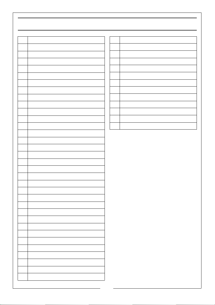
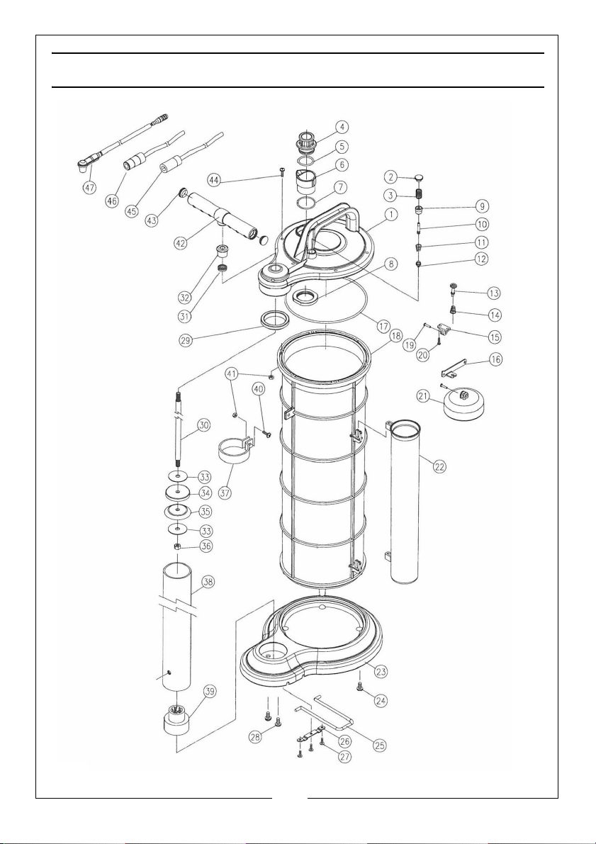
PARTS LIST
1 Housing Cover
2Release Button
3Spring
4 Fluid Inlet Coupler
5O Ring
6 Fluid Outlet Housing
7O Ring
8Lock Nut
9 Locking Bushing
10 Shaft
11 Spring
12 Check Valve
13 Safety Cup
14 Spring
15 Bracket Base
16 Arm
17 O Ring
18 Tank
19 Pin
20 Screw 3.8x10mm
21 Float
22 Tube Storage Unit
23 Base
24 Screw 6x15mm
25 Foot rest
26 Fixed Strip
27 Screw 4x10mm
28 Screw M8x16mm
29 Ring Seal
30 Shaft
31 Oil Seal
32 Holder
33 Flat Washer
34 Piston Spacer
35 Piston
36 Hex Nut M8
37 Pump Holder
38 Pump Cylinder
39 Pump Base
40 Screw M5x16mm
41 Nut M5
42 Handle
43 End Cap
44 Screw M5x20mm
45 Suction Tube With Adapter
46 Extracting Tube With Adapter
47 Brake Tube With Rubber Fitting
11
Parts & Service: 020 8988 7400 / E-mail: [email protected] or [email protected]
Page 12
 Loading...