

Clarke CHL500SD, CHL Series, CHL500D, CHL150D, CHL1000TD Assembly & Operating Instructions
...Page 1
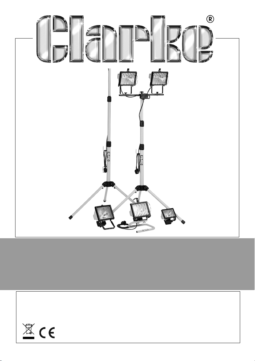
HALOGEN LIGHT
MODEL NO: CHL100-1000
PART NO: SEE PAGE 2
ASSEMBLY & OPERATING
INSTRUCTIONS
ORIGINAL INSTRUCTIONS GC0617 - ISSUE 2
Page 2
INTRODUCTION
Thank you for purchasing this CLARKE Halogen Light.
Before attempting to use this product, please read this manual thoroughly and
follow the instructions carefully. In doing so you will ensure the safety of yourself
and that of others around you, and you can look forward to your purchase
giving you long and satisfactory service.
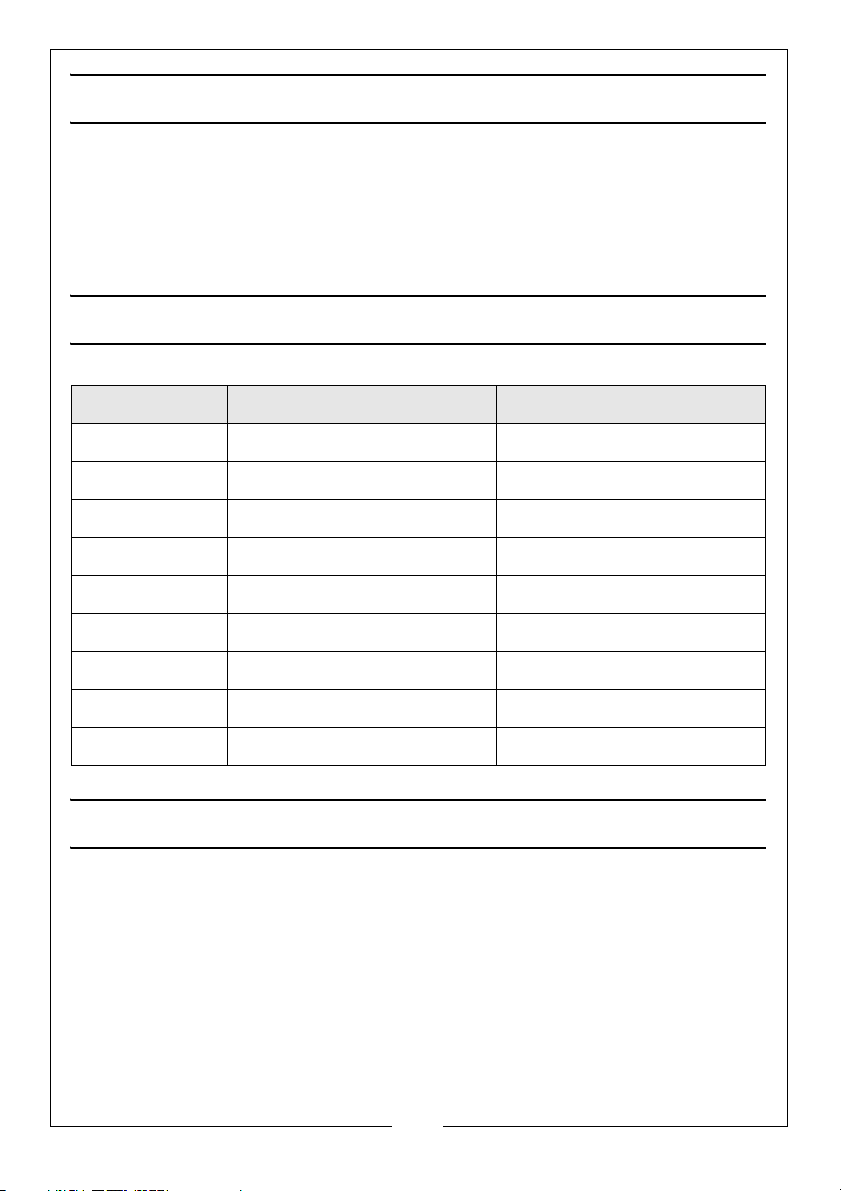
SPECIFICATIONS
Model No SUPPLY REQUIRED OUTPUT PER LAMP
CHL500D 230V 50HZ 500W
CHL500SD 230V 50HZ 500W
CHL500TD 230V 50HZ 500W
CHL1000TD 230V 50HZ 500W
CHL150D 230V 50HZ 150W
CHL151D 230V 50HZ 150W
CHL100D 110V 50HZ 500W
CHL110D 110V 50HZ 500W
CHL120D 110V 50HZ 500W
GUARANTEE
This product is guaranteed against faulty manufacture for a period of 12
months from the date of purchase. Please keep your receipt which will be
required as proof of purchase.
This guarantee is invalid if the product is found to have been abused or
tampered with in any way, or not used for the purpose for which it was
intended.
Faulty goods should be returned to their place of purchase, no product can
be returned to us without prior permission. This guarantee does not effect your
statutory rights.
2
Parts & Service: 020 8988 7400 / E-mail: [email protected] or [email protected]
Page 3
SAFETY PRECAUTIONS
1. Before moving your Halogen Light or replacing a broken part, always
ensure that the power supply is disconnected at the mains.
2. This unit must not be immersed in water.
3. Do not install this unit within 2 metres of combustible material. The lamp
housing can exceed temperatures of 110°C (230°F).
4. Do not move your Halogen Light or replace bulbs or broken parts with wet
hands, or when standing on a wet or damp surface or in water. Always
ensure the power supply is disconnected at the mains.
5. The external part of the light head develops high operating temperatures.
To avoid possible injury do not touch. Wait until the power supply has been
disconnected and the unit cooled down.
6. Do not use this lamp in hazardous locations, such as flammable or
explosive environments.
7. Do not sit directly in front of this unit, as the high operating temperatures
can burn the skin.
8. Do not look directly into the lamp when switched on as this can damage
the eyes.
9. When using tripod legs they should be suitably weighted to prevent the unit
from toppling over, causing damage to individuals or property.
10. If used with an extension cable always ensure that the extension cable is
fully unwound.
11. We recommend that a Residual Current Device (RCD) is used in
conjunction with your CLARKE Halogen Light.
12. Do not use this unit if it has a broken lens, casing or damaged supply cable.
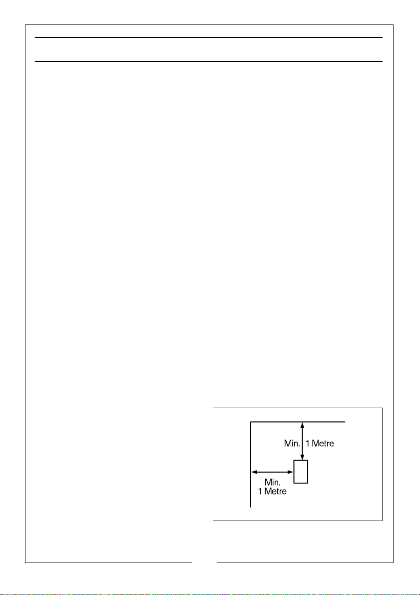
13. Always ensure that the front and
the top of the halogen lamp is at
least 1 metre away from any flat
or fixed surface (as shown).
3
Parts & Service: 020 8988 7400 / E-mail: [email protected] or [email protected]
Page 4
ELECTRICAL CONNECTIONS
Plug must be BS1363/A approved.
Always fit a 13 Amp fuse.
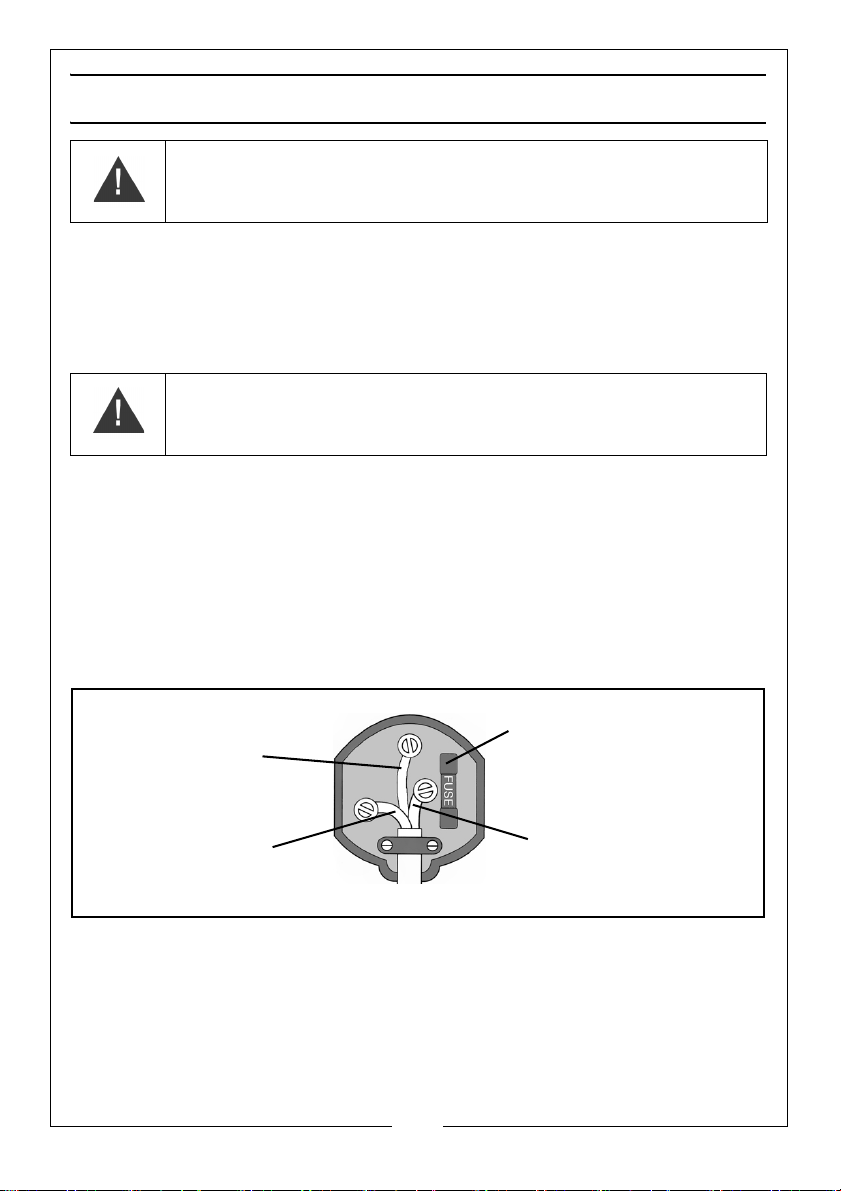
Ensure that the outer sheath of the cable is firmly held by the clamp
Neutral
(Blue)
Live
(Brown)
Earth
(Green and Yellow)
WARNING! READ THESE ELECTRICAL SAFETY INSTRUCTIONS
THOROUGHLY BEFORE CONNECTING THE PRODUCT TO THE
MAINS SUPPLY.
230 VOLT MODELS
The battery charger for this product is provided with a standard 13 amp, 230
volt (50Hz), BS 1363 plug, for connection to a standard, domestic electrical
supply. Should the plug need changing at any time, ensure that a plug of
identical specification is used.
WARNING! THE WIRES IN THE POWER CABLE OF THIS PRODUCT
ARE COLOURED IN ACCORDANCE WITH THE FOLLOWING CODE:
BLUE = NEUTRAL BROWN = LIVE
As the colours of the flexible cable of this appliance may not correspond with
the coloured markings identifying terminals in your plug, proceed as follows:
• Connect the GREEN & YELLOW coloured cord to the plug terminal
marked with a letter E or Earth symbol.
• or coloured GREEN or GREEN & YELLOW.
• Connect the BROWN coloured cord to the plug terminal marked a
letter “L” or coloured RED
We strongly recommend that this machine is connected to the mains supply
via a Residual Current Device (RCD)
If in any doubt, consult a qualified electrician. DO NOT attempt any repairs
yourself.
If this appliance is found to be fitted with a plug which is moulded on to the
electric cable (i.e. non-rewireable) please note:
Parts & Service: 020 8988 7400 / E-mail: [email protected] or [email protected]
4
Page 5

1. The plug must be thrown away if it is cut from the electric cable. There is a
danger of electric shock if it is subsequently inserted into a socket outlet.
2. Never use the plug without the fuse cover fitted.
3. Should you wish to replace a detachable fuse carrier, ensure that the
correct replacement is used (as indicated by marking or colour code).
4. Replacement fuse covers can be obtained from your local Clarke dealer
or most electrical stockists.
FUSE RATING
The fuse in the plug must be replaced with one of the same rating and this
replacement must be ASTA approved to BS1362.
We strongly recommend that this machine is connected to the mains supply
via a Residual Current Device (RCD).
110 VOLT MODELS
These units include a fitted industrial plug to BS4343 and MUST be connected
to a 110 Volt, 1 phase 50Hz supply through a suitably fused isolator switch.
The user should purchase a suitable connecting lead which is compatible with
the appliance socket. A length of 2-3 metres is recommended as giving
mobility to the heater but without becoming a trip hazard.?????????????
If in any doubt, consult a qualified electrician. DO NOT attempt any electrical
repairs yourself.
5
Parts & Service: 020 8988 7400 / E-mail: [email protected] or [email protected]
Page 6
ASSEMBLY & MOUNTING INSTRUCTIONS
INSTALLING THE BULB AND GRILL
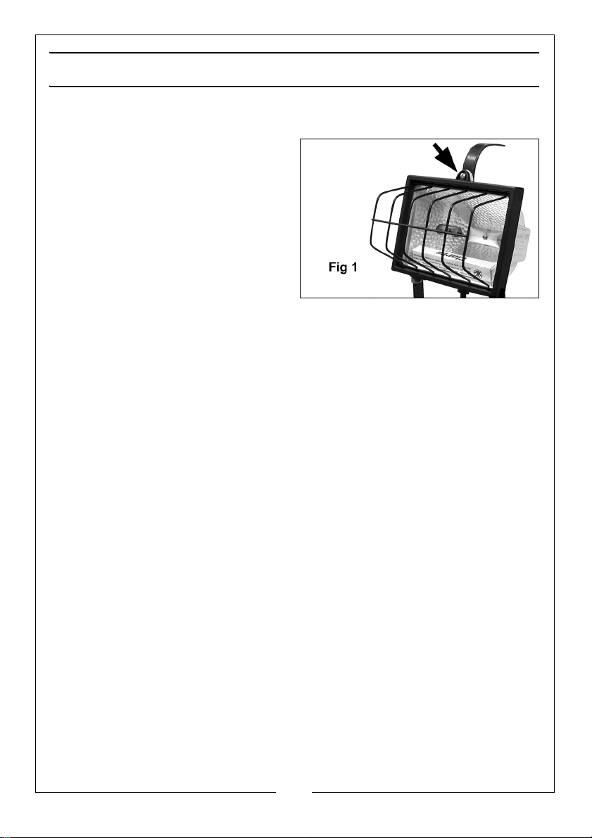
The bulb is stored within the lamp
housing as illustrated in Fig 1.
1. Remove the wing nut securing the
handle where fitted, and then the
screw securing the lamp housing
cover, arrowed in Fig.1, and install
the halogen bulb as follows:
2. Holding the bulb with a soft cloth,
carefully locate one end into the
ceramic mounting. Whilst pushing
the end of the bulb against the metal pin, gently slide the other end of the
bulb into position in the other ceramic mounting until it is secure. Do not use
force when installing the bulb.
NOTE: DO NOT TOUCH THE BULB WITH FINGERS, this will cause damage. If
it has been touched, wipe it carefully with a soft cloth dampened
with methylated spirits.
3. To install the grill, Gently prise out the glass - ease one side of the frame
sideways. Slide the grill into place ensuring it locates correctly into its slots one at each corner, then replace the glass. Finally screw the lamp housing
cover back firmly, ensuring the gasket is correctly seated, then reattach
the handle where fitted.
MODELS 150D &500D ONLY
These models are designed for wall or other independent mounting and may
be used with PIR or other security systems. They are not supplied with electric
cable.
The cable used should be suitable for outdoor use, 3-core with a conductor
size of at least 1.5mm2, manufactured to BS6500.
6
Parts & Service: 020 8988 7400 / E-mail: [email protected] or [email protected]
Page 7
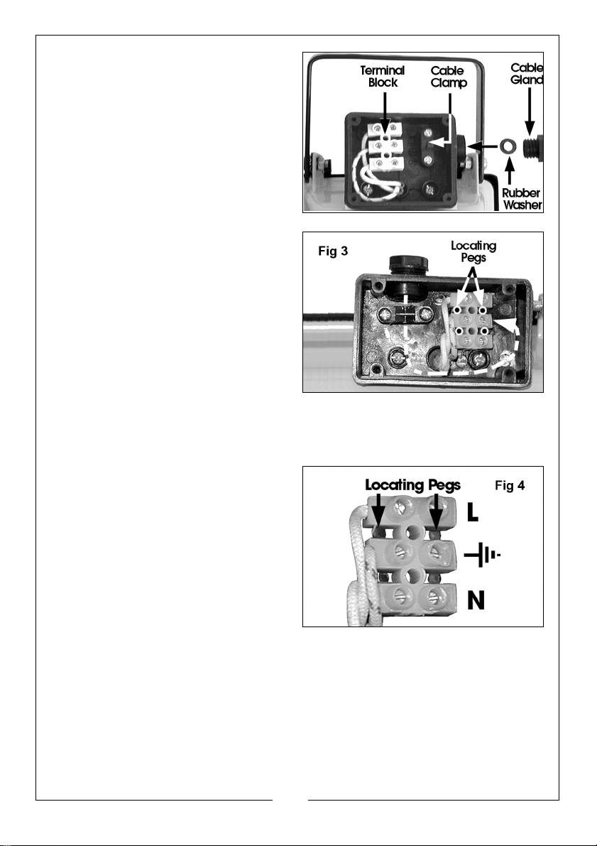
Wiring up these models should be
carried out as follows:
1. Remove the cable gland and
rubber washer from the cable
inlet and retain. Fig. 2 shows the
gland and washer removed from
model 150D.
2. Remove the Terminal Box cover
by unscrewing the four securing
screws.
3. Remove the screws securing the
cable clamp.
4. Thread the cable gland, followed
by the rubber washer over the
cable, then thread the cable
through the cable inlet.
5. Carefully strip the outer insulation
from the conductors for a
distance of approx. 30mm taking
care not to damage the
conductor insulation.
6. Strip the conductor insulation, for a distance of approx. 8mm and twist the
strands together, on each conductor.
7. Identify the terminals by observing
the embossed symbols on the
base of the junction box, and
indicated in Fig.4.
These are L - Live, N - Neutral and
earth.
Connect the conductors
accordingly.
NOTE: The cable path for the 500SD
is shown by the dotted line in
Fig. 3.
8. Replace the cable clamp ensuring it firmly clamps the OUTER insulation, or
sheathing, and NOT the conductors.
9. Push the rubber washer into the cable inlet and screw in the cable gland
firmly. Do not overtighten as this could strip the plastic threads.
10. Before replacing the cover, ensure the terminal black is located snugly on
the locating pegs, illustrated in Figs. 3 and 4.
7
Parts & Service: 020 8988 7400 / E-mail: [email protected] or [email protected]
Page 8
The cover should be firmly secured, but again, do not overtighten the screws.
The lamp may be mounted to a convenient surface using the holes provided
in the mounting bracket, and then tilted to the desired angle. Tighten the
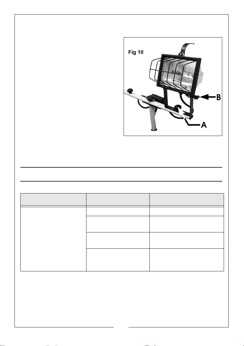
mounting bracket pivot screws (B, Fig.10) to secure.
MODELS 100D, 151D & 500SD
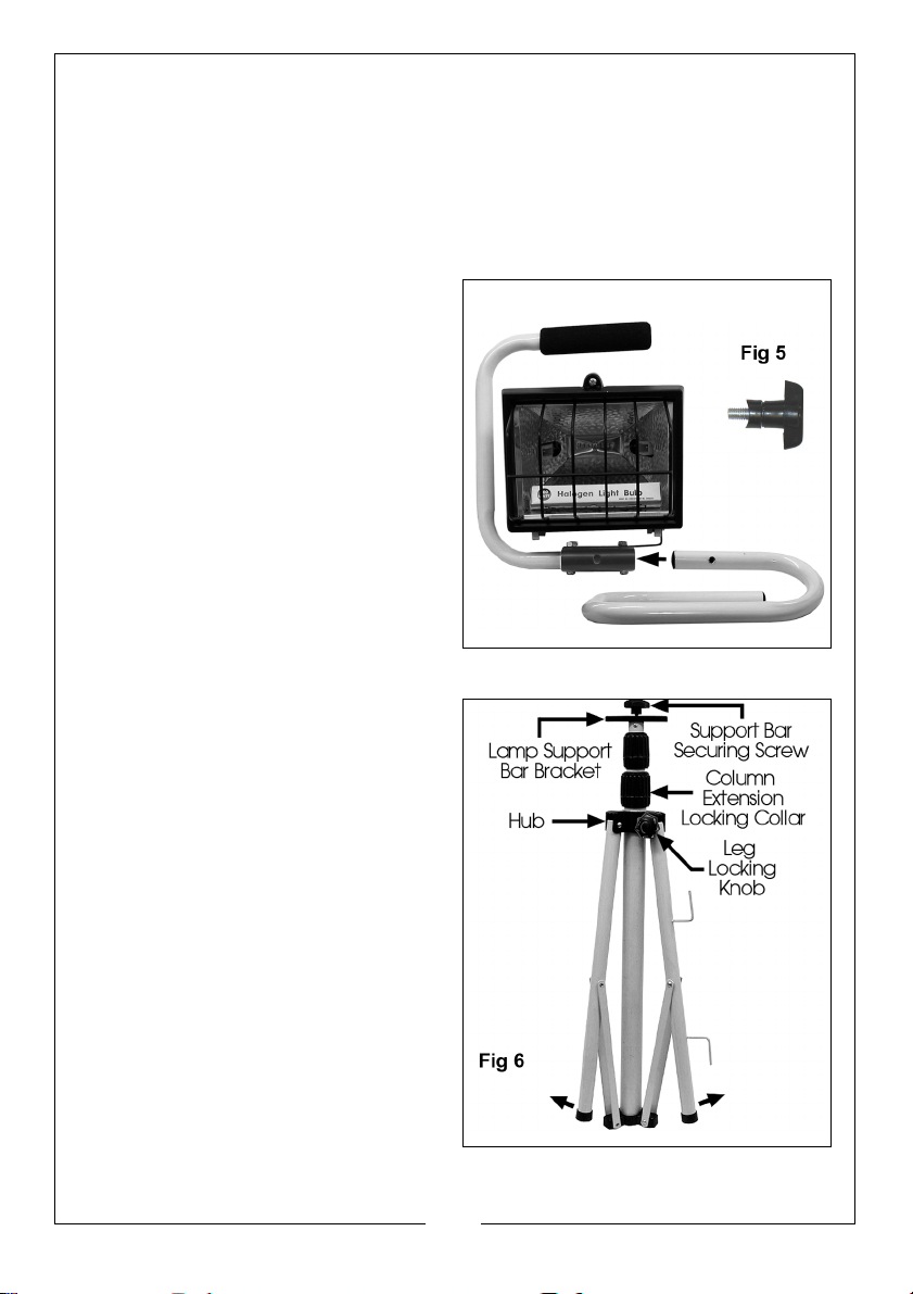
These models are mounted on a carry frame, which is assembled as follows:
1. Remove the fixing screw (inset
Fig.5) from the base of the carry
frame, then insert the tubular base
into the frame attachment, as
indicated in Fig. 5.
2. Line up the holes in the two
sections of the frame then
replace and tighten the fixing
screw.
OTHER MODELS
All other models are tripod mounted,
either single lamp or twin
THE TRIPOD
The tripod is folded so that the legs lie flat along the column.
To erect the stand, pull the legs away
from the column by prising them from
within the support linkage, taking care
not to trap your fingers. Pull the legs in
the direction of the arrows shown in
Fig. 6.
The hub will slide down the legs and
the legs will spread.
NOTE: It may be necessary to
slacken the Leg Locking Knob
in order for the hub to move.
Remember to retighten when
the legs are spread correctly.
8
Parts & Service: 020 8988 7400 / E-mail: [email protected] or [email protected]
Page 9
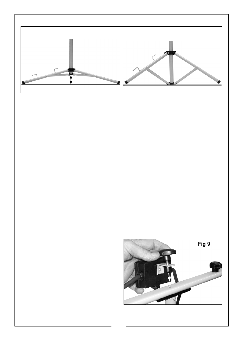
IMPORTANT: Ensure the legs are spread wide enough so that the centre
Fig 7 Fig 8
column is clear of the ground as shown in Fig 7., otherwise the centre
column will act as a fourth leg and the stand will therefore be unstable. Fig.
8 illustrates the stand in an unstable condition.
The tripod is telescopic up to a max. height of 2M (excluding the height of the
lamps). The two extension pieces are locked by the Column Locking Collars
shown in Fig.6.
To extend the column, grasp the column with one hand and turn the
respective locking collar anticlockwise to unlock. Pull out the extension tube to
the desired height and re-lock by turning the collar clockwise.
NOTE: In the interests of safety, it is recommended that the tripod legs be
secured by placing sand bags or similar weights over each leg, if
this unit is used:
• On uneven or rocky surfaces.
• With a long extension cable.
• In windy conditions; or when any of the extension tubes are
extended beyond the normal closed position.
THE LAMPS
Lamps on the single lamp models are
simply attached to the top of the
column using the single securing
screw provided in the centre hole of
the lamps’ mounting bracket.
The twin lamp models should be
assembled as follows:
1. Remove the support bar securing
screw from the top of the tripod
column (see Fig. 6).
9
Parts & Service: 020 8988 7400 / E-mail: [email protected] or [email protected]
Page 10
2. Rest the lamp support bar on the bracket on top of the column as shown in
Fig.9.
3. With the two lamps being
supported (e.g., resting on a
workbench or similar, in order to
take their weight), thread the
securing screw through the hole in
the cable junction box fixing
bracket, as shown in Fig.9,
through the hole in the lamp
support bar, and screw it into the
threaded hole on top of the
column. Ensure it is tight.
4. Attach the lamps to the support
bar using the single screw
provided and shown at ’A’, Fig.10.
NOTE: The lamp may be swivelled
by slackening the screw ‘A’
Fig.10, or tilted by slackening the screw ‘B’. Ensure the screws are
tightened when adjustments are completed.
TROUBLESHOOTING
SYMPTOM PROBLEM SOLUTION
Lamp will not operate. Bulb broken Replace bulb
Poor contact between
lamp and socket.
Improper wiring. Have unit checked by a
Incorrrect voltage: voltage at fixture too high/
low.
10
Parts & Service: 020 8988 7400 / E-mail: [email protected] or [email protected]
Check to see if lamp is
securely installed in socket
qualified electrician.
Have supply checked by a
qualified electrician.
Page 11
MAINTENANCE
1. Clean the lens at regular intervals using a non-abrasive glass cleaner.
2. When handling the bulb use clean paper or cloth...DO NOT allow your
fingers to come into contact with the glass
REPLACEMENT BULBS
Replacement bulbs can be obtained from your local dealer or Clarke
International Spares Department.
230V, 150W Part No. 5460625
230V, 500W Part No. 5460503
110V, 150W Part No. 5460620
110V, 500W Part No. 5460504
ENVIRONMENTAL RECYCLING POLICY
Through purchase of this product, the customer is taking on the obligation to
deal with the WEEE in accordance with the WEEE regulations in relation to the
treatment, recycling & recovery and environmentally sound disposal of the
WEEE.
In effect, this means that this product must not be disposed of with general
household waste. It must be disposed of according to the laws governing
Waste Electrical and Electronic Equipment (WEEE) at a recognised disposal
facility.
11
Parts & Service: 020 8988 7400 / E-mail: [email protected] or [email protected]
Page 12

 Loading...