

Page 1

NON-SUBMERSIBLE
NON-SUBMERSIBLE
WATER PUMP
WATER PUMP
CEB102
Part Nos. 7230325
OPERATING & MAINTENANCE
INSTRUCTIONS
0410
Page 2
Thank you for purchasing this CLARKE Water Pump, which is a general purpose
pump, suitable for a variety of applications involving the transfer of clean, cold
water ONLY.
The CEB102 has a brass body designed for longer life, and an increased resistance
to corrosion.
To help ensure long, trouble free performance and the protection afforded by the
warranty, please follow carefully all the instructions and recommendations given in
this booklet.
GUARANTEE
This CLARKE product is guaranteed against faulty manufacture for a period of 12
months from the date of purchase. Please keep your receipt as proof of purchase.
This guarantee is invalid if the product is found to have been abused or tampered
with in any way, or not used for the purpose for which it was intended.
Faulty goods should be returned to their place of purchase. No product can be
returned to us without prior permission. This guarantee does not effect your
statutory rights.
SAFETY PRECAUTIONS
1. Ensure the pump is installed in a horizontal position with the outlet facing
vertically upwards, and that it is firmly anchored via its fixing screws.
2. Ensure there is an adequate air flow around the pump. DO NOT mount it in an
enclosed atmosphere.
3. Ensure all water pipes - supply or discharge, are adequately supported where
necessary, so as not to put a strain on the pump connections.
4. DO NOT allow the pump to run dry, as this will cause serious damage to the
pump seals.
5. Ensure the inlet to the pump is completely unrestricted.
6. Ensure the pump is protected from the elements, neither the motor nor the
electrical terminal box is intended to be waterproof.
7. Ensure that all pipes are protected against damage where necessary, and
that they are suitably lagged to avoid the possibility of freezing during cold
weather.
8. DO NOT attempt to pump water when the ambient temperature is greater
than 40ºC or the water temperature is greater than
9. DO NOT use this pump for pumping anything other than CLEAN WATER
10. DO NOT wrap the pump motor or pump head in cold conditions in the
mistaken belief that this will stop the pump from freezing.
11. ALWAYS install a foot valve/filter when lifting water (suction lifting), Foot filters
are available from your CLARKE dealer.
40ºC or less than 0ºC.
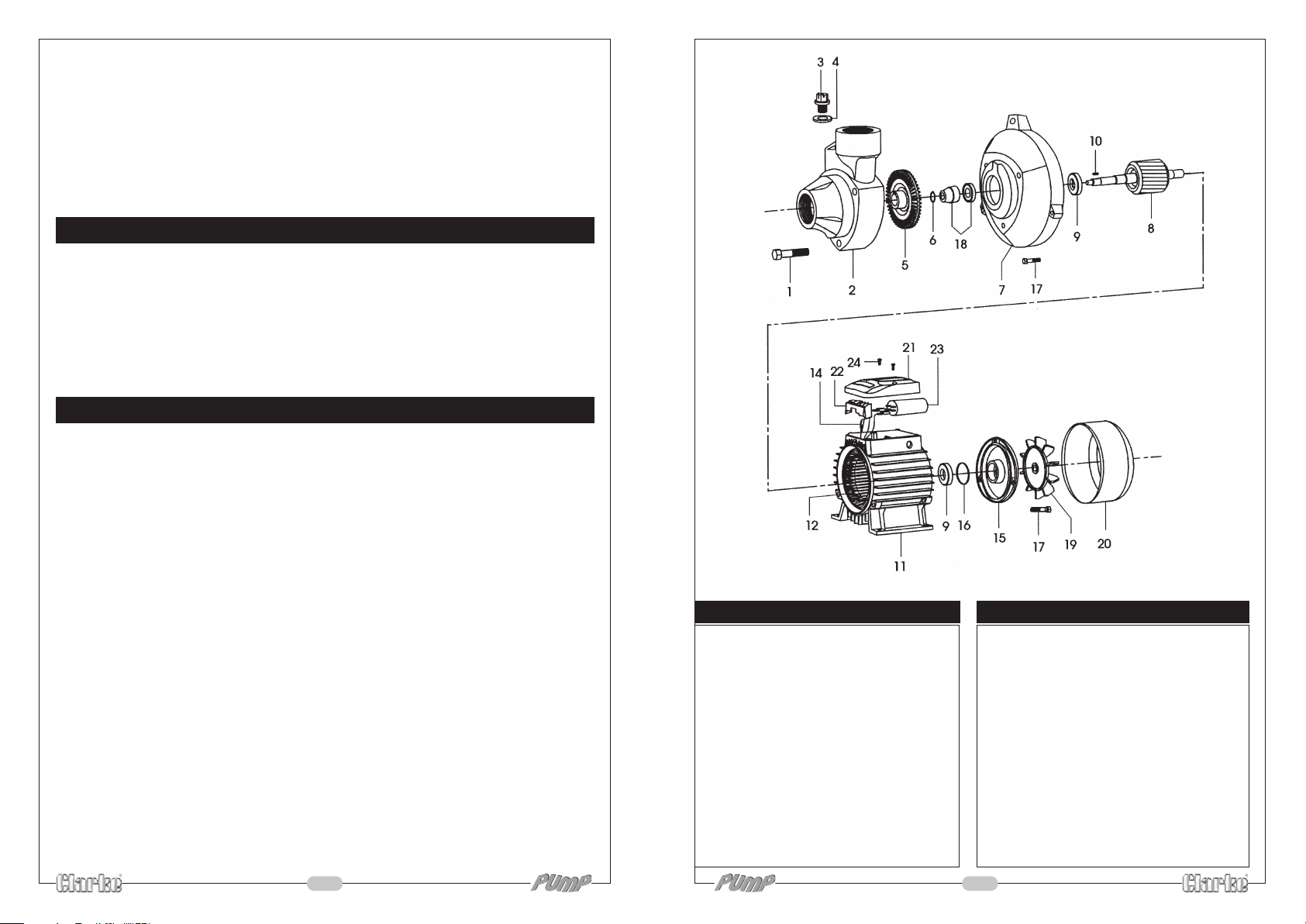
Description Part No
1 Bolt 7G01
2 Pump Body ZG02B
3 Priming Plug 7G03
4 Washer ZG04
5 Impeller ZG05
6 Locking Ring 7G06
7 Front Cover ZG07B
8 Rotor ZG08
9 Ball Bearing ZG09
10 Key ZG10
11 Main Body ZG11
12 Stator Compl. ZG12
Description Part No
13 Stator Coil ZG13
14 Connection Wire ZG14
15 Motor End Cover ZG15
16 Spring Washer ZG16
17 Bolt ZG17
18 Mechanical Seal 7G18
19 Fan ZG19
20 Fan Cover ZG20
21 Terminal Cover ZH21
22 Terminal Block ZG22
23 Capacitor ZG23
24 Screw ZG24
2
7
Page 3
ACCESSORIES
ELECTRICAL CONNECTIONS
1” Foot Valve Filter 7950561
1” BSP Spigot Hose Connector 7950210
1” I.D. Reinforced Hose for suction and delivery. 7955010
1” I.D. Layflat Hose for delivery only. 7955110
SPECIFICATIONS
CEB102
Motor 230V 50Hz 1ph
Power 0.5HP (370W)
Speed 2850 RPM
Max. Head 35M
Max. Lift (Suction) 8M
Bore Size 1”BSP
Max. Output 35 litres/min
Weight 6.25kg
Part Number 7230325
Please note that the details and specifications contained herein, are correct at the time of going to
print. However, CLARKE International reserve the right to change specifications at any time without prior
notice. Always consult the pump’s data plate
When disposing of this product, do not dispose of with general waste. It must be disposed of according to the laws
governing Waste Electrical and Electronic equipment, at a recognised disposal facility.
PARTS & SERVICE
PARTS & SERVICE
CLARKE International, on one of the following numbers.
Please contact your nearest dealer, or
PARTS & SERVICE TEL: 020 8988 7400
PARTS & SERVICE FAX: 020 8558 3622
WARNING: THIS MACHINE MUST BE EARTHED.
Installation should be carried out by a qualified electrician in accordance with
I.E.E. Regulations. However, in the further interests of safety we would emphasize
the following :-
This pump should be connected to a standard domestic 13 amp, 230 volt (50Hz),
electrical supply and we strongly recommend that the connection be made via
a Residual Current Device (RCD).
IMPORTANT: Should the supply be taken from a normal 13 amp socket, then the
plug used must be to BS 1363 standard, and the wires should be wired up in
accordance with the following colour code:
Green & Yellow .......... Earth or marked with a letter “E” or Earth symbol “ ”.
Blue ............................. Neutral or terminal marked with a letter “N”
Brown .......................... Live or terminal marked with a letter “L”
FUSE RATING
The fuse in the plug must be rated at 5 amps
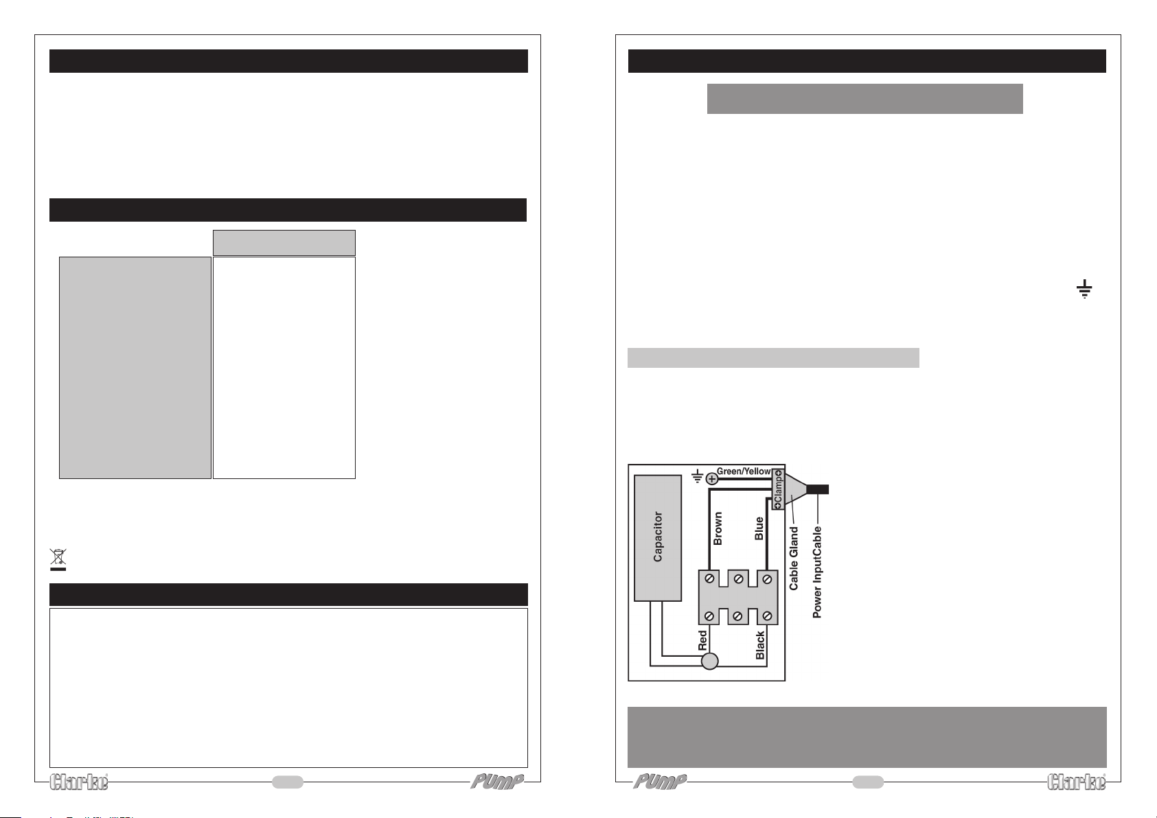
The pump MUST be wired according to the diagram below, and ensuring the
following precautions are strictly observed:
1. The cable used must be of sufficient size
to ensure it is a tight fit in the cable gland.
2. Ensure the cable gland is correctly used.
The clamp must firmly clamp the outer
cable sheath and NOT the conductors.
3. Ensure the earth conductor is correctly
connected to the earth terminal.
The bare conductor should be wrapped
around the body of the screw, positioned
between the two washers, and the screw
suitably tightened.
or e-mail as follows:
PARTS: [email protected]
SERVICE: [email protected]
6
WARNING:
DO NOT attempt electrical installation work if you are in any doubt as to how it
should be properly carried out. Consult a qualified electrician.
3
Page 4
WATER CONNECTIONS
IMPORTANT: The pump must not be connected to the power supply until the hose/
pipe installation is completed.
If any part of the system is to be connected to the mains water supply, do ensure
that you comply with your local water authority regulations.
Because of the variety of possible installations, no plumbing accessories are supplied
as standard with your pump. However, accessories designed specifically for this
range of pumps are available from your CLARKE dealer and are listed on page 7.
The pump must always be installed and operated in a horizontal position i.e. with
the outlet port facing vertically upwards. The fixing holes in the base should be
used as necessary to secure the pump firmly in its operating position. Also, ensure
that there is adequate air circulation around the motor.
Avoid situations where there is the risk of water coming into contact with the
outside of the pump. Neither the motor or the terminal box are intended to be
waterproof.
These notes are for guidance on how to achieve a proper working system.
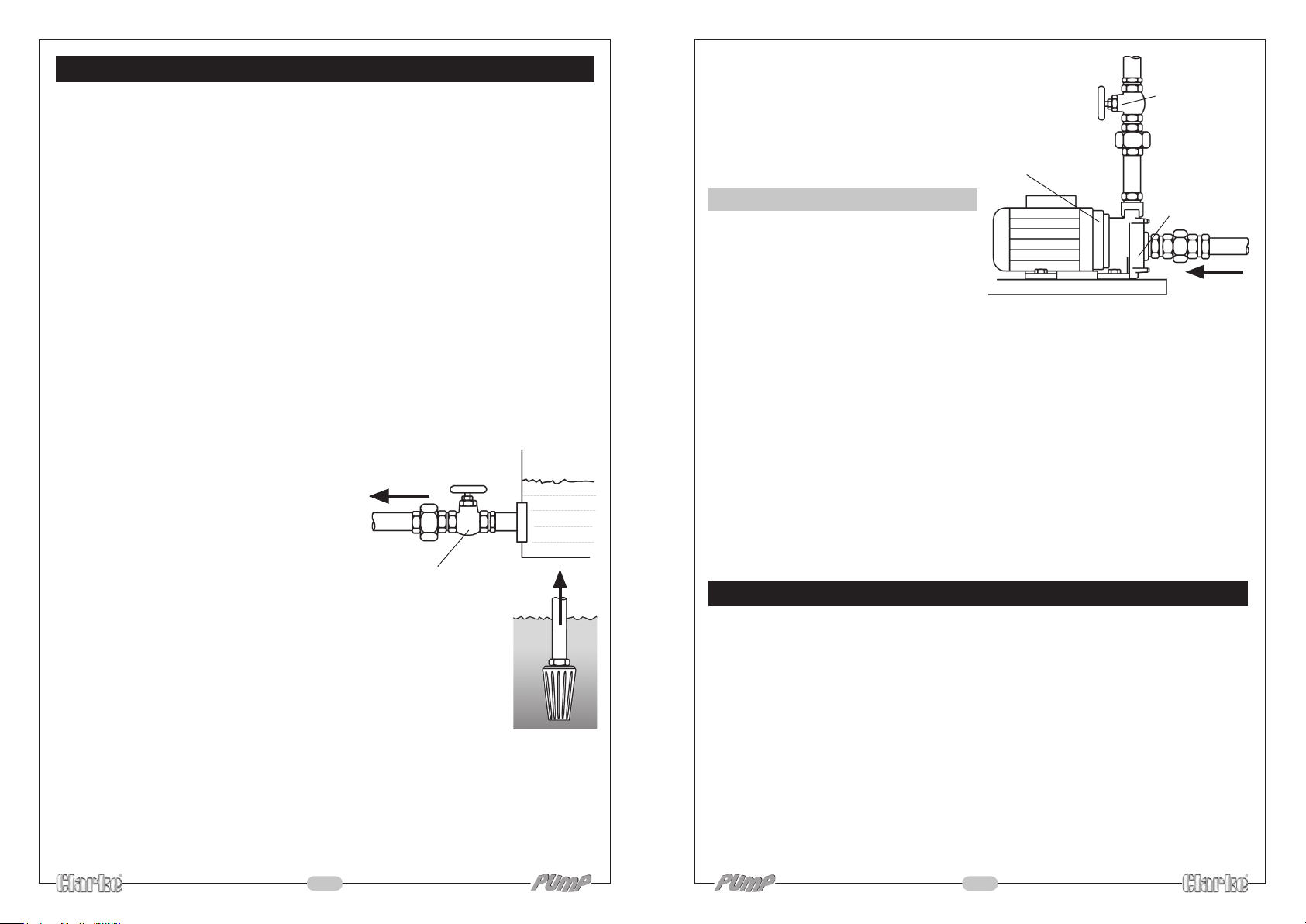
The schematic diagrams illustrate possible methods of pipework installation. Water
intake can be by means of either:-
Water being taken in by the pump should,
whenever possible, be fed by means of
gravity (Method A). However, if this is not
possible then water may be drawn from a
lower level by means of suction (Method B).
The suction lift i.e. the vertical distance
between the water level and the pump
should not exceed distance specified for your
pump (see Specifications on page 7).
When using this method, a foot valve, must be fitted to the lower
end of the suction hose, (as illustrated), so as to help retain water
in the suction system.
The delivery head i.e. the vertical distance between the pump
and the point of discharge should be at least 5 feet. If this cannot
be achieved naturally, then it can be simulated by restricting the
outlet flow from the pump.
The illustration shows a gate valve (V) installed in-line on the
delivery side of the pump which can be set as required to regulate
the flow of water.
Do not place any such restriction on the suction side of the pump unless it serves
only to isolate a gravity fed water supply.
To prevent unnecessary strain or possible distortion to the pump, ensure that
adequate support is provided to the hoses and/or pipes. Remember they will be
considerably heavier when filled with water.
A. Gravity Feed
4
or
B. Suction Lift.
A - Gravity Feed
To Pump
Isolating Valve
Filter Foot
Valve
Should sand, chemical or other
contaminant come into contact with the
pump, flush through with cold clean
water as soon as possible.
Protect the pump and pipework from
freezing. The formation of ice may cause
serious damage.
PRIMING
When suction lift is used to draw water into
the pump it is essential that all connections
and hoses are completely air tight,
otherwise the system will not work.
Before pumping will start it is necessary
to completely fill the suction side with
water. This is known as priming the pump and is carried out as follows :-
B - Suction lift
Outlet Port
Outlet Restricter
V
Inlet Port
Valve
From Supply
1. With the pump, all pipes/hoses and the foot valve in position, unscrew the
priming plug (small hexagon nut on top of pump body, adjacent to the pump
outlet) and fill to capacity with clean water. Replace the priming plug.
NOTE: As the filler hole is quite small, it is recommended that you fill the inlet pipe with water
before it is connected to the pump, and top up through the filler plug once the pipe is
connected.
2. Adjust any device which may be fitted to the outlet side of the pump, so as to
ensure as great a flow as possible.
3. Switch on the pump. Water should start to flow through the system. Check for
leaks and adjust the flow if necessary using the gate valve (or other type of
restriction) on the delivery side of the pump. Remember that some resistance
(head) is required on the outlet side of the pump to prevent motor overload.
TROUBLE SHOOTING
If the system is set up properly, there is little likelihood of problems arising, but if
water will not flow as it should then check the following points:-
1. The suction hose and connections including the filler plug need to be
completely air tight, otherwise air will be drawn in and either reduce or
completely stop the flow of water.
2. Ensure that the system has been fully primed with water up to the level of the
filler plug.
3. Check to see that no foreign matter is fouling the intake system and check
the filter is not blocked or obstructed.
4. Check that the vertical height between the level of the water intake and the
ultimate discharge point does not exceed 38 metres. If this should be the
case then the height must be reduced.
Should you still experience problems, then contact your Clarke dealer, or CLARKE
International Service Department for advice.
5
 Loading...