

Page 1
DRILL STAND WITH VICE
Model No: CDS3
Part No: 6500224
ASSEMBLY INSTRUCTIONS
GC09/13
Page 2
INTRODUCTION
Thank you for purchasing this CLARKE product.
Please read and follow the instructions carefully. In doing so you will ensure
the safety of yourself and others around you, and you can look forward to
the product giving you long and satisfactory service.
Please keep these instructions in a safe place for future reference
GUARANTEE
This product is guaranteed against faulty manufacture for a period of 12
months from the date of purchase. Please keep your receipt which will be
required as proof of purchase.
This guarantee is invalid if the product is found to have been abused or
tampered with in any way, or not used for its intended purpose. Faulty goods
should be returned to their place of purchase. No product can be returned
to us without prior permission.
This guarantee does not effect your statutory rights.
SPECIFICATION
erutaeF noisnemiD
htpeDgnillirDmumixaMmm06
thgieHnmuloCmm005
thgieWgk83.3
)HxWxD(snoisnemiDmm894x061x253
seziSralloCllirDmm34/83
2
Parts & Service: 020 8988 7400/E-mail:[email protected] or [email protected]
Page 3
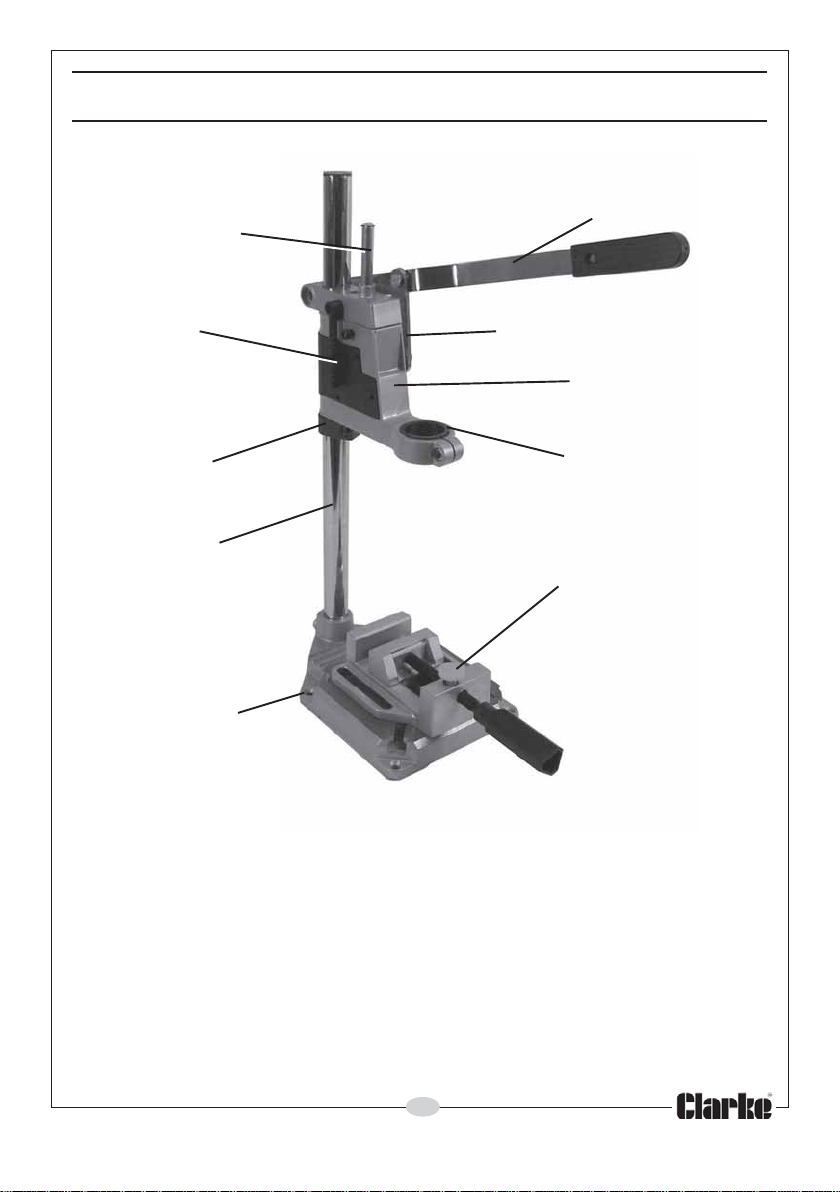
COMPONENT PARTS
DEPTH ADJUSTER
ROD
DEPTH SCALE
LOWER COLLAR
COLUMN
MOUNTING HOLE
OPERATING LEVER
CONNECTING ARM
HEAD ASSEMBLY
DRILL LOCKING COLLAR
WITH REDUCING SLEEVE
VICE JAW QUICK
RELEASE
FIG 1
The component parts of your CDS3 drill stand are shown in fig 1.
• Any electric drill with a standard 43mm diameter neck may be fitted
directly to the head assembly.
• A reducing sleeve is provided, allowing a drill with a 38mm diameter neck
also to be accommodated.
• The depth of travel of the drill may be controlled by using the depth
adjuster. A depth scale is provided so that accurate drilling depths may
be set.
3
Parts & Service: 020 8988 7400/E-mail:[email protected] or [email protected]
Page 4
ASSEMBLY
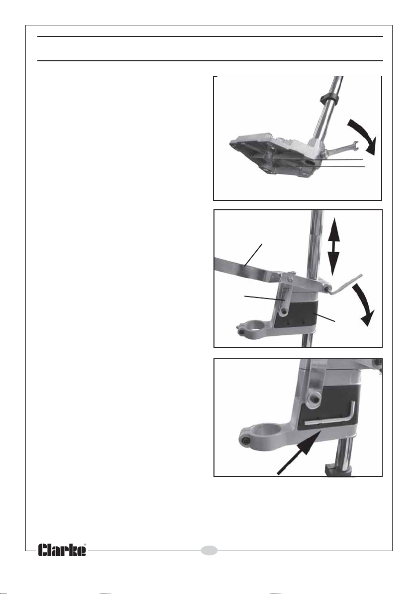
1. Insert the column into the base
and secure with the bolt using a
14mm wrench.
• Ensure the column does not
project below the base.
2. Slide the lower collar onto the
column and secure
approximately half way up the
column using the hex key.
3. Slide the head assembly onto the
column.
4. Attach the operating lever to
both the head assembly and to
the connecting arm using the
nut/bolt at one end, using a
10mm wrench and tighten the
hex key loosely at the other end.
Fig 2
Operating Lever
Connecting
Arm
Fig 3
Column level
with base
Head
Assembly
5. Always store the hex key in the
clips on the side of the head
assembly.
Fig 4
4
Parts & Service: 020 8988 7400/E-mail:[email protected] or [email protected]
Page 5
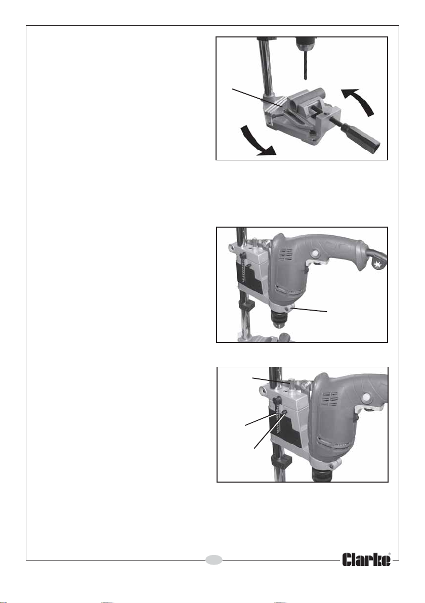
6. Secure the vice to the base using
two suitable bolts with nuts and
washers (not supplied).
• To position the vice relative to
the column, slacken the two
vice securing bolts and
manoeuvre the vice as
required.
Bolt/nut
IMPORTANT!
Fig 5
Secure the base to a workbench or sturdy table using suitable bolts (not
supplied). Drill the work-bench/table accordingly, using the four mounting
holes in the stand base as a template.
FITTING A DRILL
1. Fit an electric drill with a
standard 43mm diameter neck to
the head assembly and secure in
the locking collar as shown in Fig
6. Tighten the locking collar using
the hex key.
2. If using a drill with a 38mm neck,
fit the reducing sleeve provided
into the locking collar before
Hex bolt in
locking collar
inserting the drill.
SETTING THE DEPTH
1. Decide on the depth of hole
required to be drilled.
2. Release the hex head bolt which
locks the depth adjusting rod.
3. Using the operating arm, lower
the drill until the required reading
is showing on the scale and lock
the depth adjuster rod at this
position using the hex key.
4. It is recommended that a light
smearing of lubricant be applied to the column to assist with free
movement.
Depth
Adjusting
Rod
Depth
Scale
Hex head
bolt
Fig 6
Fig 7
5
Parts & Service: 020 8988 7400/E-mail:[email protected] or [email protected]
Page 6
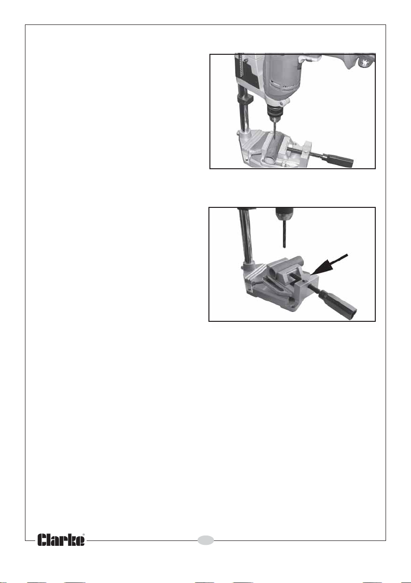
DRILLING THE HOLE
1. Lower the head assembly until
the drill bit is just touching the
workpiece as in Fig 8, and set the
head assembly in position using
the hex key shown in Fig 3.
2. Switch the drill on, and press
down on the operating lever as
the drill bit starts drilling. The
depth of hole will be restricted by
the depth stop.
ADJUSTING THE VICE
1. A quick setting button is provided
for the vice jaw adjustment. Press
the red button whilst pushing IN or
pulling OUT the handle.
Fig 8
Fig 9
6
Parts & Service: 020 8988 7400/E-mail:[email protected] or [email protected]
Page 7

NOTES
__________________________________________________________________________
__________________________________________________________________________
__________________________________________________________________________
__________________________________________________________________________
__________________________________________________________________________
__________________________________________________________________________
__________________________________________________________________________
__________________________________________________________________________
__________________________________________________________________________
__________________________________________________________________________
__________________________________________________________________________
__________________________________________________________________________
__________________________________________________________________________
__________________________________________________________________________
7
Parts & Service: 020 8988 7400/E-mail:[email protected] or [email protected]
Page 8
 Loading...