

Page 1
OPERATING & MAINTAINENCE
INSTRUCTIONS
0508
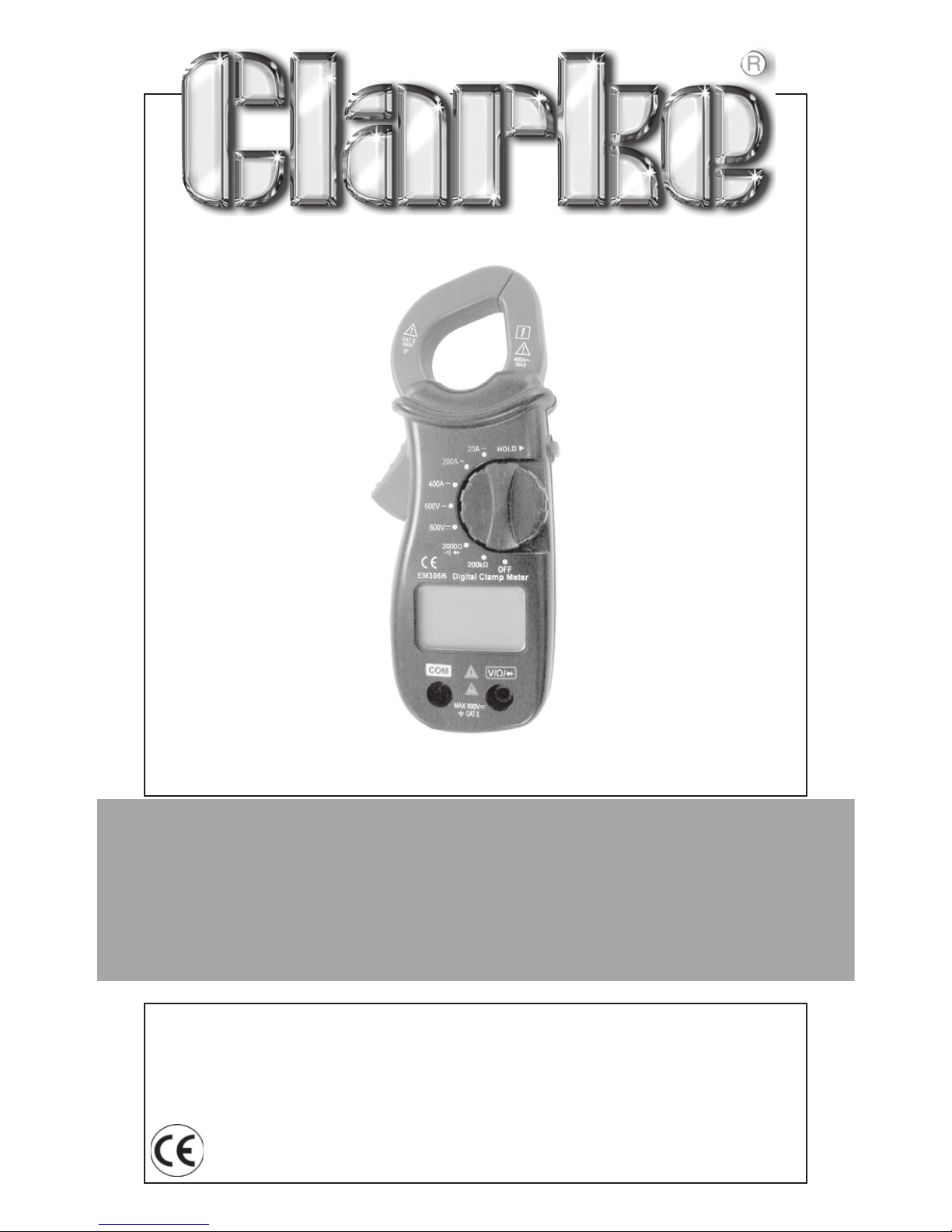
OPEN JAW DIGITAL MULTIMETER
OPEN JAW DIGITAL MULTIMETER
MODEL No: CDM85
Part No: 4500095
Page 2

2
Thank you for purchasing this CLARKE CDM85 Digital Multimeter.
Please read this leaflet thoroughly and follow the instructions
carefully, in doing so you will ensure that operations are carried out in
complete safety, and you can look forward to the tool giving you
long and satisfactory service.
GUARANTEE
This CLARKE product is guaranteed against faulty manufacture for a
period of 12 months from the date of purchase. Please keep your
receipt as proof of purchase. This guarantee is invalid if the product is
found to have been abused or tampered with in any way, or not used
for the purpose for which it was intended.
Faulty goods should be returned to their place of purchase, no
product can be returned to us without prior permission.
This guarantee does not effect your statutory rights.
SAFETY INFORMATION
This clamp meter has been designed according to IEC-61010
concerning electronic measuring instruments with a measurement
category (CAT II 600 V) .
ELECTRICAL SYMBOLS
~ AC (Alternating Current)
DC (Direct Current)
· Important safety information. Refer to the manual.
· Dangerous voltage may be present.
Earth ground
Conforms to European Union directives
Double insulated
Diode
Page 3

3
WARNING
To avoid possible electric shock or personal injury, follow these
guidelines:
• Do not use the meter if it is damaged. Before you use the meter,
inspect the case. Pay particular attention to the insulation
surrounding the connectors.
• Inspect the test leads for damaged insulation or exposed metal.
Check the test leads for continuity. Replace damaged test leads
before you use the meter.
• Do not use the meter if it operates abnormally. Protection may
be impaired. When in doubt, have the meter serviced.
• Do not operate the meter around explosive gas, vapor, or dust.
• Do not apply more than the rated voltage, as marked on the
meter, between terminals or between any terminal and earth
ground.
• Before use, verify the meter’s operation by measuring a known
voltage.
• When servicing the meter, use only specified replacement parts.
• Use with caution when working above 30V ac rms, 42V peak, or
60V dc. Such voltages pose a shock hazard.
• When using the probes, keep your fingers behind the finger
guards on the probes.
• Connect the common test lead before you connect the live test
lead. When you disconnect test leads, disconnect the live test
lead first.
• Remove the test leads from the meter before you open the
battery door or measure AC current.
• Do not operate the meter with the battery door or portions of the
case removed or loosened.
• To avoid false readings, which could lead to possible electric
shock or personal injury, replace the batteries as soon as the low
battery indicator appears.
• Before using the clamp jaws to clamp the conductor to be
measured, make sure that all the test leads have been removed
from the clamp meter.
• Remove test leads from the meter and remove the clamp jaw
from the clamped conductor before opening the meter case or
the battery door.
Page 4

4
• Remaining endangerment: When an input terminal is connected
to dangerous live potential it is to be noted that this potential at
all other terminals can occur!
• CATII - Measurement Category II is for measurements performed
on circuits directly connected to low voltage insta I lation. (Exam
pies are measurements on household appliances, portable tools
and similar equipments.) Do not use the meter for measurements
within Measurement Categories III and IV.
CAUTION
To avoid possible damage to the meter or to the equipment under
test, follow these guidelines:
• Disconnect circuit power and discharge all high-voltage
capacitors before testing resistance,diode and continuity.
• Use the proper function and range for your measurements.
• Before moving the rotary switch to change functions, disconnect
test leads from the circuit under test and remove the clamp jaws
from the clamped conductor.
GENERAL SPECIFICATION
Display: ........................................ 3 1/2 -digit LCD
Overrange indication : .............. “1” shown on LCD
Sampling rate: ............................ Approximate 3 times per sec.
Jaw opening capability : .......... 27mm
Max. measurable conductor : .. (D 25mm
Battery : ....................................... 3V, CR2032, three batteries
Operation temperature : .......... 0°C -40°C <75%RH
Storage temperature : ............... -20°C -60 °C, <85%RH
Dimensions: ................................ 151 mm X 65mm X 34mm
Weight : ....................................... about 127g( including battery )
Page 5
5
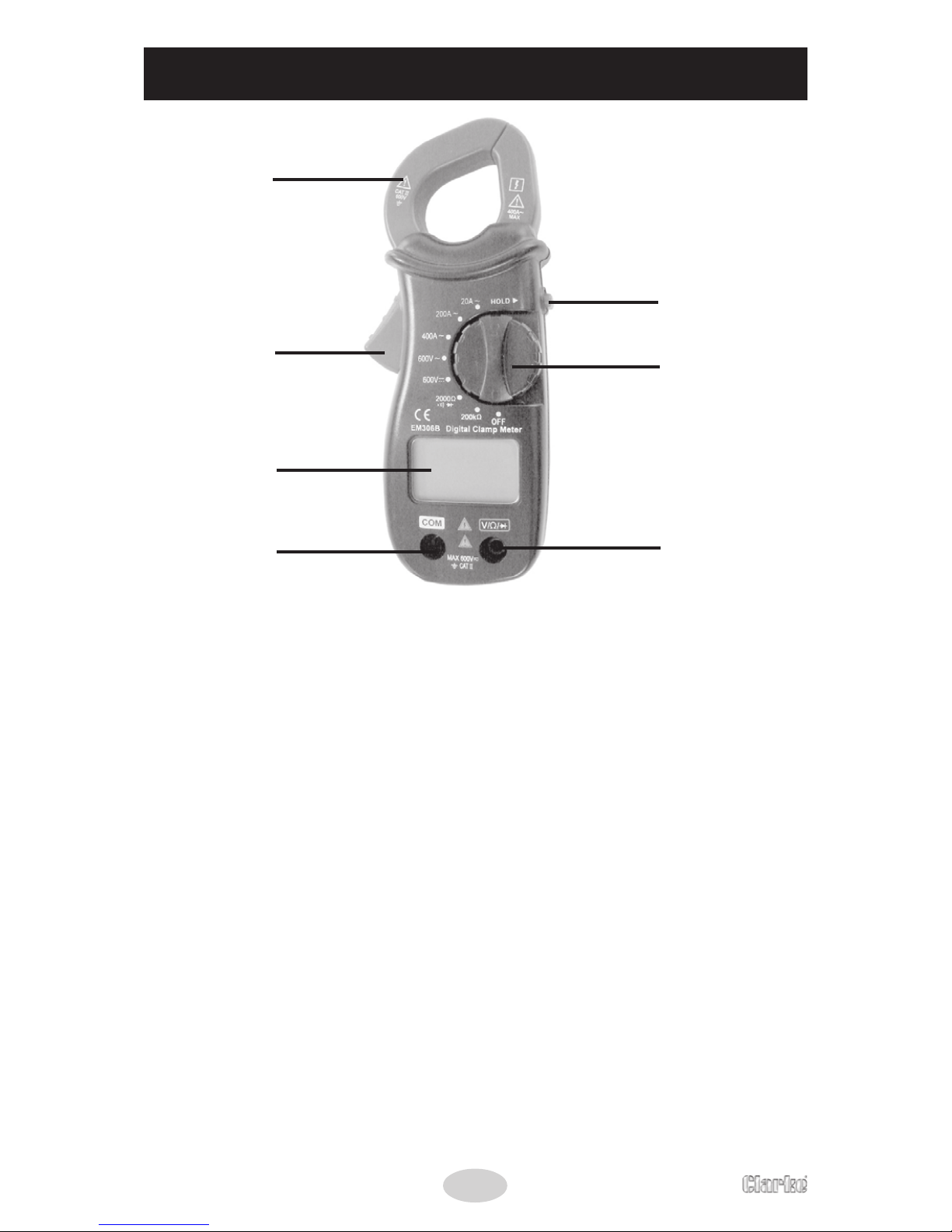
PARTS ID
1. Clamp Jaw
Used to clamp the conductor to be measured. To get more
accurate reading, the conductor should be in the center of the
jaws.
2. Trigger
Used to open and close the jaws for AC current measurement.
3. Display
3 1/2-digit LCD, with a max. reading 1999.
4. “COM” Jack
Plug-in jack for the black (Negative) test lead.
5. “V Q -0+” Jack
Plug-in jack for the red (Positive) test lead.
6. Rotary Switch
Used to select desirable function and range as well as to turn the
meter on/off.
7. “HOLD” Button
After pressing the button, the present reading is held on the
display, meanwhile “HOLD” is displayed on LCD as an indicator.
To exit the Hold Mode, press the button again and the indicator
“HOLD” will disappear.
1
2
3
4
5
6
7
Page 6
6
OPERATING INSTRUCTIONS
Measuring DC Voltage
1 Insert the plug of the black test lead to the “COM” jack, the
plug of the red test lead to the ‘V Ω ’ jack.
2 Set the rotary switch to “600V position.
3 Connect the test leads to the source or load to be measured.
4 Read the voltage value on the LCD. The polarity of the red test
lead connection will be indicated as well.
Measuring AC Voltage
1 Insert the plug of the black test lead to the “COM” jack, the plug
of the red test lead to the ‘V Ω ’ jack.
2 Set the rotary switch to “600V ~position.
3 Connect the test leads to the source or load to be measured.
4 Read the voltage value on the LCD.
Measuring AC Current
1 Set the rotary switch to the desired AC current range position.
2 Press the trigger and clamp the conductor to be measured with
the jaws.
Make sure that the jaws are perfectly closed.
Note:
a. Each time only one conductor should be clamped.
b. The conductor should be in the center of the area closed
by the jaws in order to get an accurate reading.
c. Don’t touch the conductor with your hand or skin.
3 Read the reading on the display.
Page 7
7
Measuring Resistance
1 Insert the plug of the black test lead to the “COM” jack, the plug
of the red test lead to the ‘V Ω ’ jack.
2 Set the rotary switch to the desired resistance range position
(“2000Ω “ or “200kΩ “).
3 Connect the test leads across the load to be measured.
4 Read the reading on LCD.
Note:
The built-in buzzer will sound when the resistance being measured is
less than about 30Ω with the rotary switch in “2000Ω” position.
Before you do in-circuit resistance measurement, make sure that the
power of the circuit has been disconnected and all the capacitors
have been discharged.
Measuring for continuity
1 Insert the plug of the black test lead to the “COM” jack, the plug
of the red test lead to the ‘V Ω ’ jack.
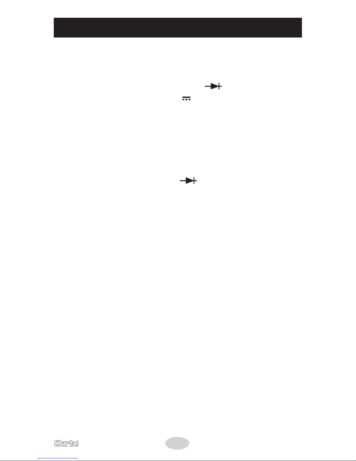
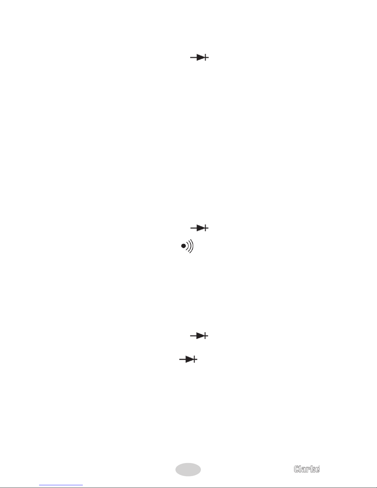
2 Set the rotary switch to the “ “ position.
3 Connect the test leads across the load to be measured.
4 When the resistance being measured is less than about 30Ω, the
buzzer will sound.
Measuring Diode
1 Insert the plug of the black test lead to the “COM” jack, the plug
of the red test lead to the ‘V Ω ’ jack. ( the polarity of the red
test lead is “+”).
2 Set the rotary switch to the “ ” position.
3 Connect red test lead to the anode of the diode, black test lead
to the cathode of the diode.
Read the approximate forward voltage on LCD.
Note: Reading’s unit is “mV”.
Page 8
8
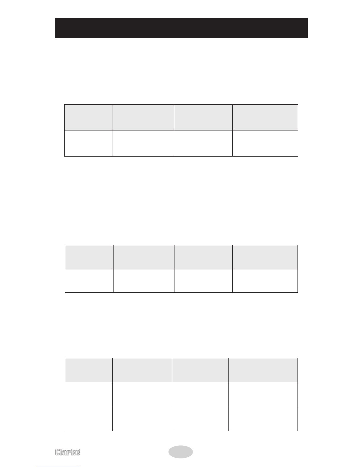
TEST RANGE SPECIFICATION
Accuracy specifications take the form of:
±(% of Reading+number of least significant digits).
AC Voltage
egnaR noituloseR ycaruccA
daolrevO
noitcetorP
V006V1)3+%2.1(±
V006CD
smrv006CA
Input impedance: 9MΩ
Frequency Response: 40Hz~400Hz
Maximum permited input voltage: 600Vrms
DC Voltage
egnaR noituloseR ycaruccA
daolrevO
noitcetorP
V006V1)2+%0.1(±
V006CD
smrv006CA
Input impedance: 9MΩ
Maximum permited input voltage: 600Vrms
Resistance
egnaR noituloseR ycaruccA
daolrevO
noitcetorP
0002
Ω
1
Ω
)2+%2.1(±
V052CD
smrV052CA
k002
Ω
001
Ω
)2+%5.1(±
V052CD
smrV052CA
Page 9
9
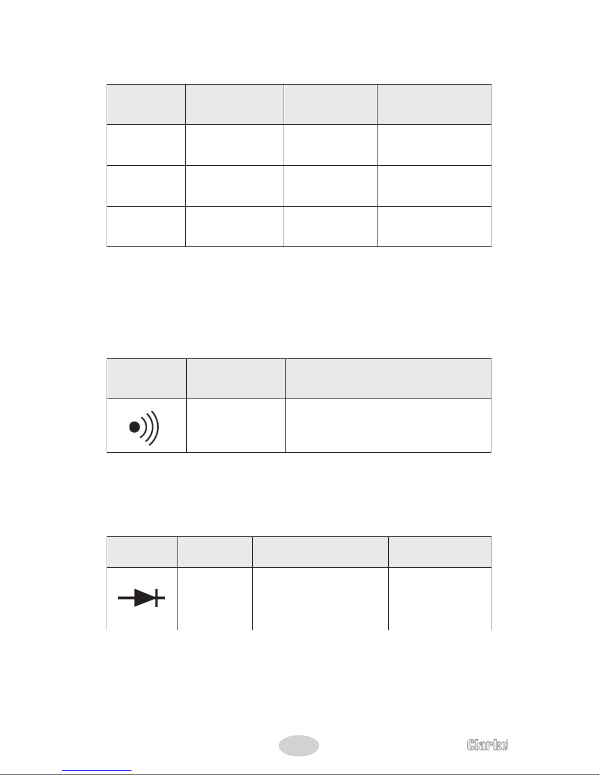
AC Current
egnaR noituloseR ycaruccA
daolrevO
noitcetorP
A02Am01)5+%0.3(±
A005
)sdnoceS03(
A002Am001)5+%5.2(±
A005
)sdnoceS03(
A004A1)5+%5.2(±
A005
)sdnoc
eS03(
Response: Average, calibrated in rms of a sine wave
Frequency range: 50 ~ 60 Hz
Audible Continuity
egnaR noituloseR ycaruccA
1
Ω
spordecnatsiserehtnehW
03tuobawoleb
Ω
rezzubehT,
dnuoslliw
Diode
egnaR noituloseR ycaruccA
daolrevO
noitcetorP
Vm1
drawrof.xorppA
eblliwpordegatlov
.deyalpsid
egatlovtiucricnepo(
)V3dnuorasi
V052CD
smr
V052CA
Page 10
10
GENERAL MAINTAINANCE
Periodically wipe the case with a damp cloth and mild detergent. Do
not use abrasives or solvents.
Dirt or moisture in the jacks can affect readings.
Clean the jacks as follows:
1 Make sure that no object is clamped in the jaws.
2 Turn the meter off and remove the test leads.
3 Shake out any dirt that may be in the jacks.
4 Soak a new swab with alcohol. Work the swab around in each
jack.
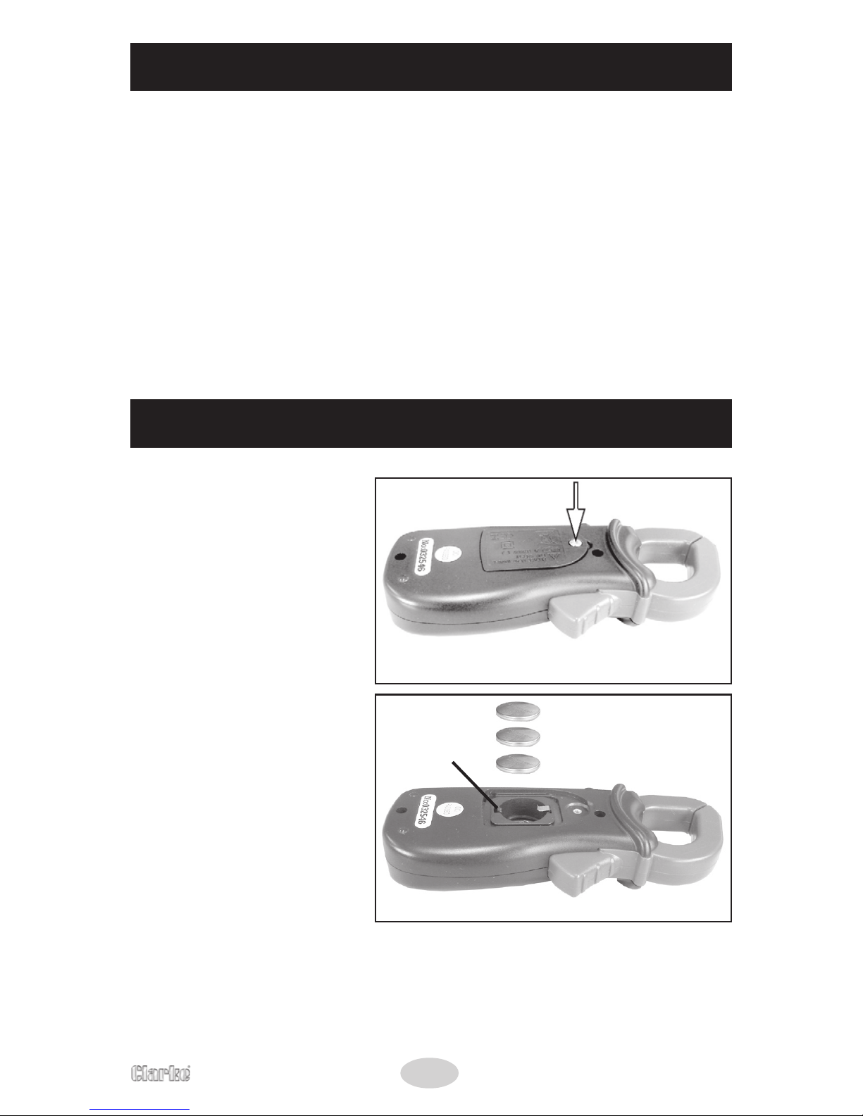
BATTERY REPLACEMENT
1 Remove the screw
from the battery cover.
2. Gently pull back the
battery release clip and
remove the 3 batteries.
3. Replace the 3 batteries,
making sure that the
positive side is facing
upwards on each
battery.
The batteries required
are 3 x CR2032
Dispose of your old
batteries in
accordence with
local regulations.
Battery
release
clip
3 x CR2032
Page 11

11
NOTES
Page 12

 Loading...