

Page 1

6 - 1 SUPER DETECTOR WITH LCD6 - 1 SUPER DETECTOR WITH LCD
MODEL No: CDM75
Part No: 4500145
OPERATING & MAINTENANCE
INSTRUCTIONS
1207
Page 2

INTRODUCTION
Thank you for purchasing your new CLARKE 6 - 1 SUPER
DETECTOR WITH LCD. Before use, please read this instruction
manual thoroughly and follow all directions carefully.
The CLARKE 6 - 1 SUPER DETECTOR WITH LCD is ideal for DIY and
Trade use.
GUARANTEE
• This product is guaranteed against manufacturing faults
for a period of 12 months from the date of purchase.
• Keep your receipt as proof of purchase.
• This guarantee is invalid if the product is found to have
been abused or tampered with in any way, or not used
for the purpose for which it is intended. The reason for
return must be clearly stated.
• This guarantee does not affect your statutory rights.
DECLARATION OF CONFORMITY
We declare that this unit conforms to the following standards
and directives.
89/336/EEC
Dat e: 05/12/07
Signed:
D. Kemp
Title: Engineering manager
2
TIPS
• Re-calibrate the unit frequently to avoid inaccurate
readings.
• Take several readings vertically above, below, to the left
and right to confirm the reading.
• When taking measurements, make sure that there is
nothing in the way of the ultrasonic beam such as
curtains, desks etc.
Detection Depths
Metal .................................................... Copper 38 mm
................................................................... Rebar 76 mm
Studding (30 x 30mm) ........................................19 mm
AC Voltage (90-250V @50/60 Hz) .................... 50 mm
Detection depth can vary due to moisture content
and texture of the wall, paint etc.
SPECIFICATIONS
Model: ................................................................. CDM75
Part No: ............................................................. 4500145
Battery ........................................ 9V, PP3 or Equivalent
Weight: ................................................................... 180 g
Dimensions: .................. (H x W x D) 140 x 30 x 70 mm
11
Page 3
DISTANCE MEASUREMENT
Calculating room volume
To determine the approximate volume of a room:
1 Measure the width of the room.
2 Press the X button.
3. Measure the length of the room.
4. Press the X button again.
5. Measure the height of the room.
6. Press the X button again.
• The resulting volume measurement is shown on the
display.
7. The measured distance can be switched between
square feet and square metres by pressing the MODE
button.
Adding or subtracting distances
1 Measure the first distance.
2 Press the + or - button.
3. Measure second distance.
2 Press the + or - button again.
• The result is shown on the display.
• You can repeat the process, adding or subtracting
measurements indefinitely
10
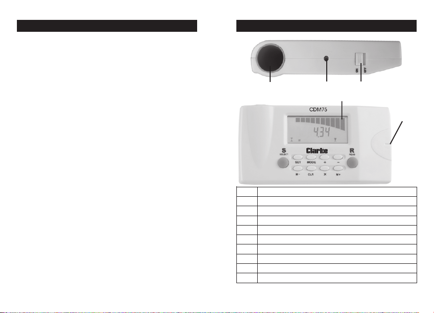
PARTS IDENTIFICATION
Maximum signal indicator
TEStniopgnitratstnemerusaemehtteS
TCELESsedom4ehthguorhtelcycotsserP
EDOM )cirteMrolairepmIsreteMroteeFnis
DAER latem/eriwca/dutsrofnacSrotnemerusaemaekatotsserP
x )snoitaluclacemulovdnaaer
+rehtegotseulavecnatsidddaotsserP
-seulavecnatsidtcartbusotsserP
+M.emu
-MatadderotsehtyalpsidotsserP
RLC .yromemehtniderotsatadeteledotd
eulavehtyalpsidotsserP
arof(stnemerusaemowtylpitlumotsserP
lohdnasserp,atadllasraelC
3
Power SwitchUltrasonic Aperture Laser
Groove
lovroaera,ecnatsidfoeulavehterotsotdesU
Page 4

Do not dispose of this product with general household
waste. It must be disposed of according to the laws
governing Waste Electrical and Electronic equipment, at
a recognised disposal facility.
INSERTING THE BATTERY
1. Remove the battery door on the rear of the unit.
2. Connect a 9V PP3 battery to the battery clip.
3. Place the battery into the compartment.
4. Replace the battery door.
AC VOLTAGE DETECTION
1. Set the power switch to the ON position.
2. Repeatedly press the SELECT button until is displayed.
Calibration
3. Hold the unit in the air away from any metal objects.
4. Press and hold the READ button.
• The unit will beep three times when calibration is
complete. Do not release the READ button.
Using
5. Keep holding the READ button and place the unit on
the wall, slowly move the unit sideways across the wall.
• When the maximum signal indicator on the LCD lights
up and the buzzer sounds, mark the point by placing a
pencil mark in the grove on top of the unit.
DISTANCE MEASUREMENT
1. Set the power switch to the ON position.
2. Repeatedly press the SELECT button until is displayed.
Using
Make sure there is a clear path between the unit and the
point you wish to measure.
3. Hold the bottom of the unit flat against a wall,
approximately halfway between the floor and the
ceiling.
4. Press the READ button once.
• The unit will beep and display the distance between the
two points. ‘E’ (error) will appear on the display if you
attempt to measure a distance longer than 18 metres.
Calculating area
1 Measure the width of the room.
2 Press the X button.
3. Measure the length of the room.
4. Press the X button again.
• The resulting area measurement is shown on the display.
5. The measured distance can be switched between
square feet and square metres by pressing the MODE
button.
4
9
Page 5

STUD DETECTION
Notes
• You can use the detector on wallpaper, however it may
not be effective on some types of foil backed
wallpapers or plasterboard.
• If the unit is placed over studding during the calibration,
the unit will not work, simply re-calibrate the unit 150 mm
away from the last place.
• The surface of the wall should be dry and flat.
• Always keep your free hand away from the wall during
detection.
• If you release the READ button at any time during
detection, you will need to carry out the calibration
procedure again.
• Knots in wood may cause false readings to occur.
• Normally, studding is placed at intervals of 40 - 60 cm.
AC VOLTAGE DETECTION
6. Continue to move the unit in the same direction until
the maximum signal indicator on the LCD goes out, then
move the unit in the reverse direction.
• Once again, mark the point at which the buzzer sounds
by placing a pencil mark in the groove on top of the
unit.
• The centre of the live wire is located mid way between
the two pencil marks.
Notes
• Some walls containing metal fibres (used in fireproofing)
will cause the detector to register a voltage over a
wider area.
• Rubbing or banging the wall may generate static
electricity, causing a false reading.
• Touching a damp wall being tested may also cause a
false reading.
• The unit will not detect wire inside metal shielding or
trunking.
8
5
Page 6

METAL DETECTION
1. Set the power switch to the ON position.
2. Repeatedly press the SELECT button until is displayed.
STUD DETECTION
1. Set the power switch to the ON position.
2. Repeatedly press the SELECT button until is displayed.
Calibration
3. Hold the unit in the air away from any metal objects.
4. Press and hold the READ button.
• The unit will beep three times when calibration is
complete. Do not release the READ button.
Using
5. Keep holding the READ button and place the unit on
the wall, slowly move the unit sideways across the wall.
• When the maximum signal indicator on the LCD lights
up and the buzzer sounds, mark the point by placing a
pencil mark in the grove on top of the unit.
6. Continue to move the unit in the same direction until
the maximum signal indicator on the LCD goes out, then
move the unit in the reverse direction.
• Once again, mark the point at which the buzzer sounds
by placing a pencil mark in the grove on top of the unit.
• The centre of the metal object is located mid way
between the two pencil marks.
Notes
• Wearing rings or other hand jewellery may cause a false
reading.
6
Calibration
3. Place the unit against the wall, press and hold the TEST
button.
• The unit will beep twice when calibration is complete.
Do not release the READ button.
Using
4. Keep holding the READ button and slowly move the unit
sideways across the wall.
• When the maximum signal indicator on the LCD lights
up and the buzzer sounds, mark the point by placing a
pencil mark in the grove on top of the unit.
5. Continue to move the unit in the same direction until
the maximum signal indicator on the LCD goes out, then
move the unit in the reverse direction.
• Once again, mark the point at which the buzzer sounds
by placing a pencil mark in the grove on top of the unit.
• The middle of the studding is located mid way between
the two pencil marks.
Always check that the “STUDDING” you have
detected is not a metal pipe,
see page 6.
7
 Loading...