

Page 1
OPERATING INSTRUCTIONS
DIGITAL CLAMP METER
OPERATING INSTRUCTIONS
DIGITAL CLAMP METER
0501
MODEL No. CDM55
MODEL No. CDM55
0501
Page 2

2
This guarantee does not effect your statutory rights.
with in any way, or not used for the purpose for which it was intended.
Faulty goods should be returned to their place of purchase, no product can be
returned to us without prior permission.
This CLARKE product is guaranteed against faulty manufacture for a period of 12
months from the date of purchase. Please keep your receipt as proof of purchase.
This guarantee is invalid if the product is found to have been abused or tampered
look forward to the tool giving you long and satisfactory service.
maintenance and inspection work on all types of electrical equipment.
Please read this leaflet thoroughly and follow the instructions carefully, in doing so
you will ensure that operations are carried out in complete safety, and you can
Thank you for purchasing this CLARKE CDM55 Digital Clamp Meter - a robust,
portable, multi-range instrument, capable of measuring DC Voltage, A/C
Voltage, Current, and Resistance, with an audible continuity function, ideal for
2
This guarantee does not effect your statutory rights.
with in any way, or not used for the purpose for which it was intended.
Faulty goods should be returned to their place of purchase, no product can be
returned to us without prior permission.
This CLARKE product is guaranteed against faulty manufacture for a period of 12
months from the date of purchase. Please keep your receipt as proof of purchase.
This guarantee is invalid if the product is found to have been abused or tampered
look forward to the tool giving you long and satisfactory service.
maintenance and inspection work on all types of electrical equipment.
Please read this leaflet thoroughly and follow the instructions carefully, in doing so
you will ensure that operations are carried out in complete safety, and you can
Thank you for purchasing this CLARKE CDM55 Digital Clamp Meter - a robust,
portable, multi-range instrument, capable of measuring DC Voltage, A/C
Voltage, Current, and Resistance, with an audible continuity function, ideal for
GUARANTEE
GUARANTEE
SERVICE E-MAIL - [email protected]
PARTS E-MAIL - [email protected]
PARTS - 020 8558 6696 : SERVICE - 020 8556 4443
PARTS & SERVICE FAX - 020 8558 3622
For Spare Parts and Servicing, please contact your nearest dealer, or
CLARKE International, on one of the following numbers.
SPARE PARTS & SERVICING
SERVICE E-MAIL - [email protected]
PARTS E-MAIL - [email protected]
PARTS - 020 8558 6696 : SERVICE - 020 8556 4443
PARTS & SERVICE FAX - 020 8558 3622
For Spare Parts and Servicing, please contact your nearest dealer, or
CLARKE International, on one of the following numbers.
SPARE PARTS & SERVICING
11
11
Page 3

10 3
BLACK test lead: Part No. KA5501
RED test lead: Part No. KA5502
Spare Test Leads are available from your Clarke dealer. Please quote the following
part numbers:
If the sign “BATT” appears on the display, it indicates that the battery should be
replaced. Remove the battery cover from the reat of the unit, secured with one
hex head screw, then remove the battery and replace with a new one.
10
BLACK test lead: Part No. KA5501
RED test lead: Part No. KA5502
Spare test leads are available from your Clarke dealer. Please quote the following
part numbers:
If the sign “BATT” appears on the display, it indicates that the battery should be
replaced. Remove the battery cover from the rear of the unit, secured with one
hex head screw, then remove the battery and replace with a new one.
BATTERY REPLACEMENT
SPARE PARTS
SPARE PARTS
BATTERY REPLACEMENT
• Select the proper Function and range for your measurement.
• Avoid severe shocks to the multimeter - do not drop.
• Do not allow the meter to be used if it is damaged or if its safety is impaired.
• WARNING: TO AVOID ELECTRIC SHOCK, USE CAUTION WHEN WORKING ABOVE 40V DC OR 25V AC
• Always disconnect the positive test lead before disconnecting the earth test lead.
• Follow all equipment safety procedures. Disconnect the input power and discharge all high-voltage
• Avoid working alone.
• When making a current measurement, turn the power off before connecting the multimeter in the
• When testing circuits take care not to touch any bare metal including the ends at the test probes.
• Never attempt to measure a voltage or current higher than the maximum rating at the meter.
circuit. Overloading a current shunt will cause excessive heat.
capacitors through a protective impedance before testing any resistance (Ohms)
RMS. SUCH VOLTAGES POSE A SHOCK HAZARD.
Read this information before using the meter. The following safe practices and proper operating
procedures should be followed when using any multimeter:
• Inspect the test leads for insulation damage or exposed metal. Damaged leads should be replaced.
• Never attempt to measure a voltage or current higher than the maximum rating at the meter.
circuit. Overloading a current shunt will cause excessive heat.
capacitors through a protective impedance before testing any resistance (Ohms)
RMS. SUCH VOLTAGES POSE A SHOCK HAZARD.
procedures should be followed when using any multimeter:
• Inspect the test leads for insulation damage or exposed metal. Damaged leads should be replaced.
• Select the proper Function and range for your measurement.
• Avoid severe shocks to the multimeter - do not drop.
• Do not allow the meter to be used if it is damaged or if its safety is impaired.
• WARNING: TO AVOID ELECTRIC SHOCK, USE CAUTION WHEN WORKING ABOVE 40V DC OR 25V AC
• Always disconnect the positive test lead before disconnecting the earth test lead.
• Follow all equipment safety procedures. Disconnect the input power and discharge all high-voltage
• Avoid working alone.
• When making a current measurement, turn the power off before connecting the multimeter in the
• When testing circuits take care not to touch any bare metal including the ends at the test probes.
SAFETY
Read this information before using the meter. The following safe practices and proper operating
SAFETY
3
Page 4
4
4
• Resistance measurement from 0.1 to 200 ohms
• Continuity Beeper
• Data-Hold function
• Backlight function
• Small, compact, robust, and lightweight.
This unit complies with 73/23/EEC, 89/336/EEC
CE STANDARDS
• AC Voltage measurement from 0.1 V to 600V.
• AC Current measurement tram 0.01 A to 600A.
• DC Voltage measurement from 0.1 V to 600V.
FEATURES
This unit complies with 73/23/EEC, 89/336/EEC & IEC1010
• Backlight function
• Small, compact, robust, and lightweight.
• Resistance measurement from 0.1 to 200 ohms
• Continuity Beeper
• Data-Hold function
• AC Voltage measurement from 0.1 V to 600V.
• AC Current measurement tram 0.01 A to 600A.
• DC Voltage measurement from 0.1 V to 600V.
CE STANDARDS
FEATURES
OHMS
Ω
200
Ω
0.1Ω
±(1%rdg+3digits)
600A
1A
±(2%rdg+7digits)
600VDC or peak AC
on all ranges
ACA
200A
20A
100mA
10mA
±(2%rdg+5digits)
±(2%rdg+5digits)
ACV
600V
1V
±(1%rdg+5digits)
600A 30 seconds
on all ranges
DCV
200V
600V
200V
100mV
±(1%rdg+5digits)
600V DC or peak AC
100mV
1V
±(0.5%rdg+1digit)
±(1%rdg+1digit)
600V DC or peak AC
on all ranges
FUNCTION
RANGE
RESOLUTION
ACCURACY
PROTECTION
OVERLOAD
OHMS
Ω
200
Ω
0.1Ω
±(1%rdg+3digits)
600A
1A
±(2%rdg+7digits)
600VDC or peak AC
on all ranges
ACA
200A
100mA
±(2%rdg+5digits)
600V
20A
10mA
1V
±(1%rdg+5digits)
±(2%rdg+5digits)
600A 30 seconds
on all ranges
ACV
DCV
600V
200V
100mV
1V
±(1%rdg+5digits)
±(1%rdg+1digit)
600V DC or peak AC
on all ranges
FUNCTION
RANGE
200V
RESOLUTION
100mV
±(0.5%rdg+1digit)
ACCURACY
600V DC or peak AC
PROTECTION
OVERLOAD
conductance is less than
approx. 30Ω ± 10Ω
9
Open circuit voltage
Buzzer sounds if
approx. 2.6V
Frequency range : 50
to 400Hz response
(Frequency range : 50
to 400Hz response)
10M on all ranges
10M on all ranges
IMPEDANCE
INPUT
conductance is less than
approx. 30Ω ± 10Ω
9
Open circuit voltage
Buzzer sounds if
approx. 2.6V
Frequency range : 50
to 400Hz response
(Frequency range : 50
to 400Hz response)
10M on all ranges
10M on all ranges
IMPEDANCE
INPUT
Page 5

8
Please note: Accuracy is specified for 1 year after calibration, and at 18ºC to 28ºC (64ºF to 82ºF), with
relative humidity to 80%.
Low Battery indication ............................................................. “BAT” appears on display
Size (LxWxH) ............................................................................... 214x81x41mm
Weight ....................................................................................... 380gm (incl. battery)
Part number .............................................................................. 4500080
Power Supply ............................................................................ 9V Battery - Neda1604 or 6F22
Display ....................................................................................... LCD 1999 counts, updates 2-3 secs
Measuring method ................................................................... Dual slope integration A/D converter
Over Range indication ............................................................ “1” appears on display
Polarity indication ..................................................................... “-” displayed for negative polarity
Operating Temperature ........................................................... 0ºC to 40ºC (32ºF to 104ºF)
Storage Temperature ............................................................... -10ºC to 50ºC (14ºF to 122ºF)
8
Max. Voltage between terminals and Earth ......................... 1000V DC or 750V RMS AC (sine)
Please note: Accuracy is specified for 1 year after calibration, and at 18ºC to 28ºC (64ºF to 82ºF), with
relative humidity to 80%.
Max. Voltage between terminals and Earth ......................... 1000V DC or 750V RMS AC (sine)
Power Supply ............................................................................ 9V Battery - Neda1604 or 6F22
Display ....................................................................................... LCD 1999 counts, updates 2-3 secs
Measuring method ................................................................... Dual slope integration A/D converter
Over Range indication ............................................................ “1” appears on display
Polarity indication ..................................................................... “-” displayed for negative polarity
Operating Temperature ........................................................... 0ºC to 40ºC (32ºF to 104ºF)
Storage Temperature ............................................................... -10ºC to 50ºC (14ºF to 122ºF)
Low Battery indication ............................................................. “BAT” appears on display
Size (LxWxH) ............................................................................... 214x81x41mm
Weight ....................................................................................... 380gm (incl. battery)
Part number .............................................................................. 4500080
SPECIFICATIONS
SPECIFICATIONS
(i) If the resistance to be measured exceeds the
indication “1” will be displayed.
input is not connected, an over range
maximum value of the range selected or the
2. Set the Rotary Switch to the Ω position and
NOTE:
connect the test leads across the resistor to be
measured.
1. Connect the BLACK test lead to the COM jack
and the RED test lead to the VΩ jack.
If continuity exists, (i.e., resistance less than
approx. 30
selected.
B. MEASURING RESISTANCE
2. Set the Rotary Switch to the position and
(The polarity of the red lead is +ve)
connect the test leads across two points of the
circuit to be tested.
Ω), the built-in buzzer will sound.
o)
)
)
over range situation and a higher range should be
NOTE: If the figure “1” is displayed, it indicates an
2. Set the Rotary Switch to the desired DCV or ACV
range position and connect the test leads
across the source or load to be measured.
A. MEASURING VOLTAGE
1. Connect the BLACK test lead to the COM jack
and the RED test lead to the V
Ω jack.
C. CONTINUITY TEST
1. Connect the BLACK test lead to the COM jack
and the RED test lead to the V
(ii) When checking in-circuit resistance, ensure the
that all capacitors have been fully discharged.
circuit under test has all power removed and
Ω jack.
(i) If the resistance to be measured exceeds the
indication “1” will be displayed.
input is not connected, an over range
maximum value of the range selected or the
2. Set the Rotary Switch to the Ω position and
NOTE:
connect the test leads across the resistor to be
measured.
1. Connect the BLACK test lead to the COM jack
and the RED test lead to the VΩ jack.
If continuity exists, (i.e., resistance less than
approx. 30Ω), the built-in buzzer will sound.
selected.
B. MEASURING RESISTANCE
2. Set the Rotary Switch to the position and
(The polarity of the red lead is +ve)
connect the test leads across two points of the
circuit to be tested.
o)
)
)
over range situation and a higher range should be
NOTE: If the figure “1” is displayed, it indicates an
2. Set the Rotary Switch to the desired DCV or ACV
range position and connect the test leads
across the source or load to be measured.
C. CONTINUITY TEST
1. Connect the BLACK test lead to the COM jack
and the RED test lead to the V Ω jack.
A. MEASURING VOLTAGE
1. Connect the BLACK test lead to the COM jack
and the RED test lead to the V Ω jack.
(ii) When checking in-circuit resistance, ensure the
that all capacitors have been fully discharged.
circuit under test has all power removed and
5
5
Page 6
6
6
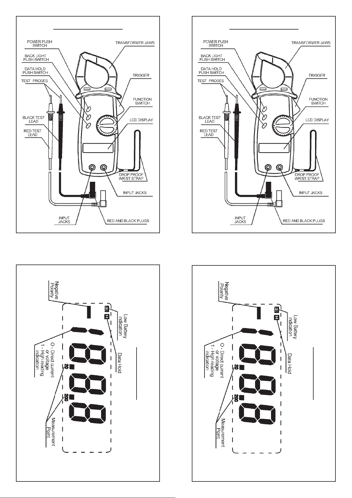
NOMENCLATURENOMENCLATURE
LCD DISPLAY
7
7
LCD DISPLAY
 Loading...