

Page 1
12in (305mm)
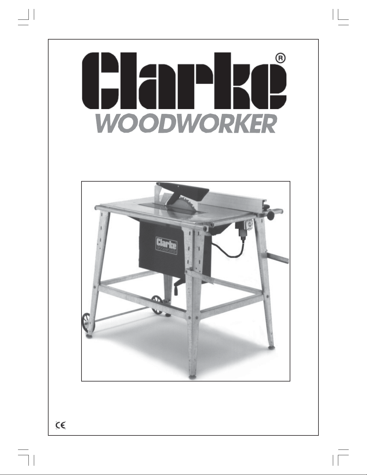
CONTRACTOR’S SAW
Model No. CCS305
Part No. 6460305
OPERATING & MAINTENANCE
INSTRUCTIONS
1
0698
Page 2
Thank you for purchasing this CLARKE 12” (305mm) Contractors Saw, which is
designed for light industrial use.
Before operating the machine, please read this booklet thoroughly and carefully
follow the instructions. In doing so you will ensure the safety of yourself and that of
others around you, and you can look forward to the Contractor’s Saw giving you
long and satisfactory service.
GUARANTEE
This CLARKE product is guaranteed against faulty manufacture for a period of 12
months from the date of purchase. Please keep your receipt as proof of purchase.
This guarantee is invalid if the product is found to have been abused or tampered
with in any way, or not used for the purpose for which it was intended.
Faulty goods should be returned to their place of purchase, no product can be
returned to us without prior permission. This guarantee does not affect your statutory
rights.
CONTENTS Page
Safety Precautions .................................................................. 3
Additional Precautions for Workshop Saws ......................... 5
Features ................................................................................... 6
Unpacking ............................................................................... 7
Assembly .................................................................................. 8
Electrical Connections.......................................................... 15
Adjustments ........................................................................... 16
Operation - Rip Sawing ....................................................... 17
Cross Cutting.................................................... 18
Maintenance ......................................................................... 19
Blade Renewal ....................................................................... 20
Specifications ......................................................................... 20
Parts List ................................................................................... 21
Parts & Servicing .................................................................... 21
Parts Diagram ........................................................................ 22
2
Page 3
SAFETY PRECAUTIONS
GENERAL SAFETY RULES FOR OPERATING MACHINERY
CAUTION:
As with all machinery, there are certain hazards involved with their operation
and use. Exercising respect and caution will considerably lessen the risk of
personal injury. However, if normal safety precautions are overlooked or
ignored, personal injury to the operator or damage to property may result.
• READ and BECOME FAMILIAR with the entire operating manual. Learn the
machine’s applications and limitations as well as the specific potential hazards
peculiar to it.
• EARTH ALL MACHINES. If the machine is equipped with a three-pin plug, it should
be plugged into a three-pin electrical socket. Never remove the earth pin.
• ALWAYS ensure that ADEQUATE LIGHTING is available. A minimum intensity of
300 lux should be provided. Ensure that lighting is placed so that you will not be
working in your own shadow.
• CHECK for DAMAGE. Before using the machine, any damaged part, such as a
guard etc., should be checked to ensure that it will operate properly, and
perform its intended function. Check for alignment of moving parts, breakage
of parts, mountings and any other condition that may affect the machine’s
operation. Any damage should be properly repaired or the part replaced. If in
doubt, DO NOT USE the machine. Consult your local dealer.
• DISCONNECT the MACHINE from the power supply before servicing and when
changing accessories such as blades, etc.
• KEEP GUARDS in place and in working order.
• ALWAYS WEAR SAFETY GOGGLES, manufactured to the latest European Safety
Standards. Also use face or dust mask if cutting operation is dusty.
Everyday eyeglasses do not have impact resistant lenses, they are NOT safety
glasses.
• KEEP WORK AREA CLEAN. Cluttered areas and benches invite accidents.
• ALWAYS WEAR EAR PROTECTORS/DEFENDERS.
• DON’T FORCE the machine, it will do a better and safer job at the rate for
which it was designed.
• REMOVE ADJUSTING KEYS AND WRENCHES. Form the habit of checking to see
that keys and adjusting wrenches are removed from the machine before
switching on.
3
Page 4

• DRUGS, ALCOHOL, MEDICATION. Do not operate machine while under the
influence of drugs, alcohol or any medication.
• USE RECOMMENDED ACCESSORIES. The use of improper accessories could be
hazardous.
• NEVER LEAVE MACHINE RUNNING UNATTENDED. Turn power OFF. Do not leave
machine until it comes to a complete stop.
• ALWAYS REMOVE PLUG from electrical outlet when adjusting, changing parts,
or working on machine.
• AVOID DANGEROUS ENVIRONMENT. Don’t use power machines in damp or wet
locations or expose them to rain. Keep your work area well illuminated.
DO NOT USE in explosive atmosphere (around paint, flammable liquids etc.).
• KEEP CHILDREN AWAY. All visitors should be kept a safe distance from the work
area, especially whilst operating the unit.
• MAINTAIN MACHINE IN TOP CONDITION. Keep tools sharp and clean for the
best and safest performance. Follow maintenance instructions.
• DON’T OVERREACH. Keep your proper footing and balance at all times. For
best footing, wear rubber soled footwear. Keep floor clear of oil, scrap wood,
etc.
• WEAR PROPER APPAREL. Loose clothing or jewellery may get caught in moving
parts. Wear protective hair covering to contain long hair.
• MAKE WORKSHOP CHILDPROOF. Cover the saw adequately when not in use, to
prevent children from damaging themselves by tampering with it.
• NEVER STAND ON THE MACHINE. Serious injury could occur if the machine is
tipped or if a cutting tool is accidentally contacted. Do not store materials
above or near a machine, such that it is necessary to stand on the machine to
reach them.
• HANDLE WITH EXTREME CARE. Whenever transporting or installing machinery,
and always use a lifting device.
• BE AWARE that many accidents are caused by carelessness due to familiarity.
ALWAYS concentrate on the job in hand, no matter how trivial it may seem.
4
Page 5

ADDITIONAL SAFETY INSTRUCTIONS for WORKSHOP SAWS
• Wear safety goggles as protection against flying wood chips and saw dust. In
many cases, a full face shield is even better protection. A dust mask is also
recommended to keep saw dust out of your lungs.
• This saw is designed for light industrial use only.
• Clear the work table of all objects except the workpiece (tools, scraps, rulers
etc.) before turning on the saw.
• Keep your fingers well away from the blade, use a push stick as you near the
end of the cut.
• Switch off the saw and make sure the blade has come to a complete stop
before clearing sawdust or off-cuts from the table.
• Make sure there are no nails or foreign objects in the part of the workpiece to
be sawn.
• Set up the machine and make all adjustments with the power OFF and
disconnected from the supply.
• DO NOT operate the machine with the guards removed. They must all be in
place and securely fastened when performing any operation.
• Use ONLY approved replacement saw blades. Contact your local CLARKE
dealer for advice. The use of inferior blades will increase the risk of injury.
• DO NOT saw any material that does not have a flat surface on which to bear.
• This machine is designed for cutting wood. DO NOT use for cutting metal or
plastic.
• DO NOT attempt to cut round or tubular work (logs etc.).
• Do not cut pieces of material which are too small to be guided by hand.
• Do not feed the workpiece through the blade too quickly, hold material firmly
and feed into blade at a moderate speed.
• When cutting a large piece of material, support it at the height of the table
with supports or use an assistant.
• Never let go of a workpiece, ALWAYS maintain control.
• Never touch, or hold on to, a piece that has been cut off whilst the power is on
or the blade is rotating.
• Ensure the surface on which the saw stands is firm, solid and non-slip.
• DO NOT use the saw for non-through-cut operations. The Upper Blade Guard
MUST be in place at all times.
5
Page 6
FEATURES
The Contractor’s Saw may be used for rip cutting or cross cutting timber up to
70mm (2¾”) in depth.
A double height Rip Fence is provided and may be secured at any desired position
for quick and accurate rip sawing. The max. width obtainable, using the rip fence is
280mm (11”).
For speed and accuracy, a guide is also provided for cross cutting. It is adjustable
so that mitres of up to 45° may be created.
The Upper Blade Guard is hinged to allow it to ride over the timber as the timber
moves over the blade.
IMPORTANT: The Blade Guard must always be in place.
The Lower Blade Guard comprises a box, on to which is mounted the motor and
saw blade. A hinged cover gives access to the blade and other components.
IMPORTANT: This cover must always be in place and secure.
The box is secured by two pivot bolts and two large (Saw Blade) Tilt Adjuster knobs.
Slackening these knobs allows the complete box, with motor and blade, to move
about the pivot bolts so that the blade may tilt by up to 45° - in one direction. It is
then secured in position by tightening the same adjuster knobs.
Extending from the bottom of the box is a handle, used for raising and lowering the
blade and is explained under ‘Operation’.
At one end of the box, (the rear end), a 48mm (17/8”) dia hole is provided for use as
a dust extraction outlet. If required it can be connected to a dust extraction device
which will provide fast and efficient removal of sawdust. The dust extractor may be
used continuously or intermittently depending upon your requirements.
Construction of the base unit is in heavy, corrosion resistant, galvanised steel and is
maintenance free. The machine is nevertheless designed for indoor use. Should it
be used outdoors, every attempt should be made to ensure it is protected from the
elements. Do not use in wet conditions.
6
Page 7
UNPACKING
Unpack the shipping carton in a clean flat area, so that you have ample room to
work, and lay out all components neatly so that they may be clearly identified.
Check to ensure that no damage was suffered in transit. Should there be any
damage, please contact your Clarke dealer immediately.
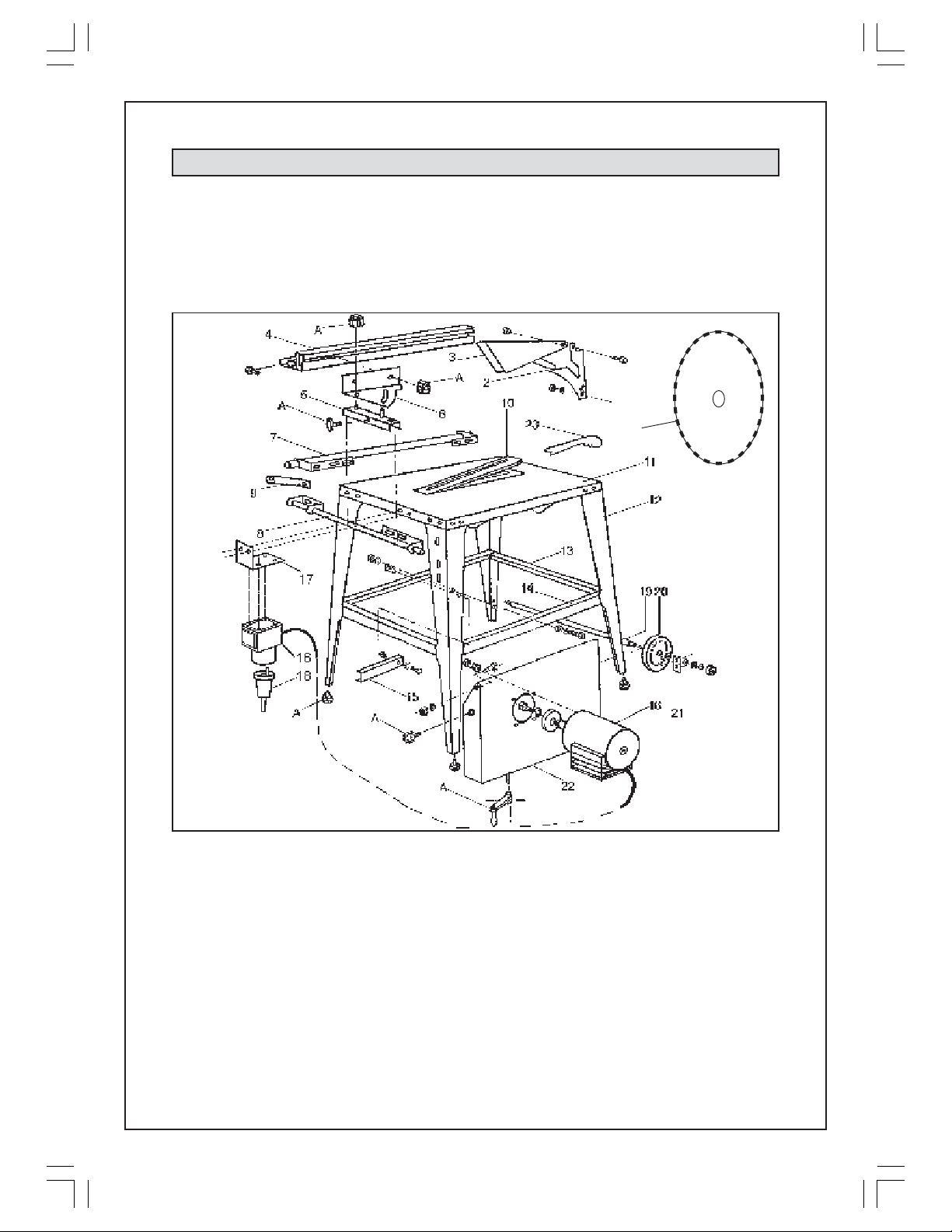
Check the parts, referring to fig.1 and the list which follows:
Fig. 1
1
1. Saw Blade
2. Riving Knife
3. Upper Blade Guard
4. Rip Fence
5. Rip Fence Support
6. Quadrant
7. Long Guide Bar (for cross cutting)
8. Short Guide Bar (for ripping)
9. Corner Support - 2 pcs
10. Table Insert
11. Table Top
12. Leg - 4 pcs
13. Short Strut - 2 pcs
14. Long Strut - 2 pcs
15. Handle - 2 pcs
16. Motor Assy.( incl. Switch Box assy).
17. Switch Box Bracket
18. Trailing Socket
19. Axle
20. Wheel - 2 pcs
21. Axle Bracket - 2 pcs
22. Lower Blade Guard Box Assy
23. Push Stick
A. 5 Scalloped Knobs ( 3 female - small, 2
male - large), 1 Winged Knob, 4 Feet and
1 Handle assy. (contained in one bag)
In addition to the foregoing list, the packing carton contains a bag with all necessary fixing screws,
nuts, collars, and washers. Please refer to the parts list for details.
7
Page 8
ASSEMBLY
A. Lower Blade Guard Box
1. Place the table face down on a sheet of cardboard (or similar).
2. Between the two side brackets lies a hinged flap. Lift and rotate it against spring
pressure through 180O so that it lies flat against the underside of the table. Hold
it in this position temporarily with a suitable weight.
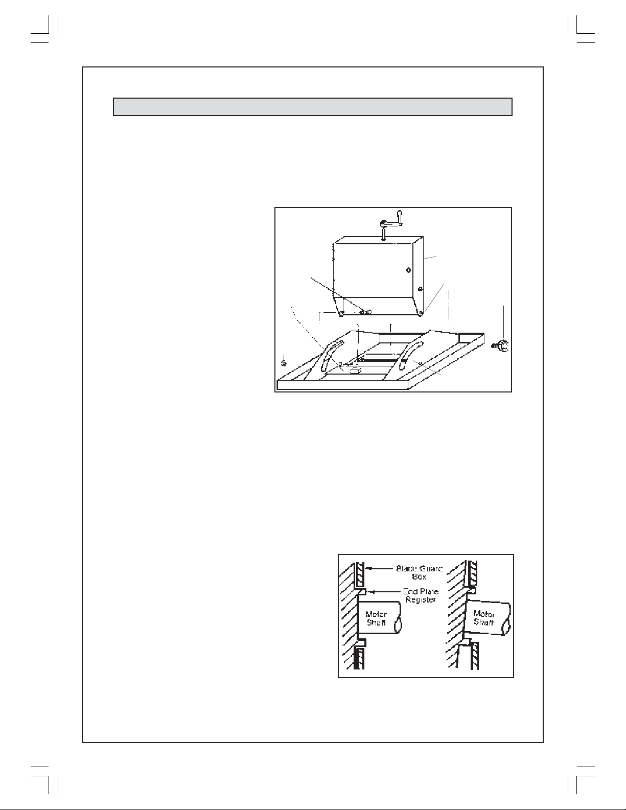
3. Invert the lower blade
guard box, and lower it
into place between the
two side brackets as
shown in fig.2, ensuring the
hinged door of the box
faces the hinged flap.
Locate the box with two
large scalloped knobs
(item A), one each side,
through the slotted holes
inthe side brackets as
shown. Screw the knobs
home but do not tighten
them fully.
These knobs are referred to as the Blade Tilt Adjuster Knobs.
4. Manoeuvre the box so that the pivot bolt holes (see fig 2), line up with the holes
in the side brackets and insert the special shouldered bolts (item B), from inside
the box.
Screw on the self locking nuts, ensuring the shoulders ofhe bolts are sitting snugly
in the holes in both the box AND the side bracket. Tighten the self locking nuts,
but only sufficiently so as to allow the box to pivot smoothly about the shouldered
bolts, and then secure the box firmly by tightening the Blade Tilt Adjuster Knobs
(A).
locking
Hinged
Flap with
weight
Self
nut
B
C
Lower Blade
Guard Box
Pivot Bolt Hole
Side Bracket
Fig. 2
A
B. Motor Assembly and Attachments
5. Insert the motor shaft through the hole in
the Blade Guard Box. The plastic cable
housing on the motor should be facing
you. i.e. when the table is on its feet, the
plastic cable box will face downwards.
Secure the motor assembly to the
moveable plate, within the box, using four
M5 x 25mm screws with flat and spring
washers. Tighten the screws to no more
than 12 lbf ft.
NOTE: It is strongly advised that assistance be used to support the weight of the
motor, when tightening the screws, to avoid the possibility of it tilting.
8
✓
Fig 2A
✗
Page 9
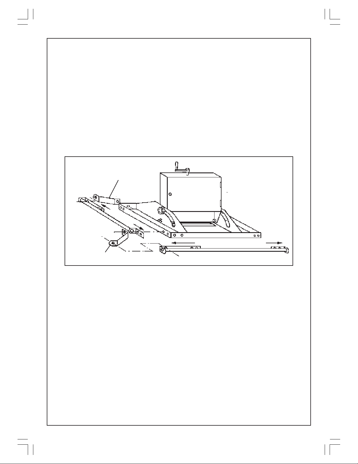
IMPORTANT: Make absolutely sure that the motors’ end plate sits snugly in the hole
in the Blade Guard Box, as shown in Fig2A. The register on the end plate must be
completely through the hole.
6. Attach the Blade Height Adjuster Handle (fig.2 item C), to the adjuster bolt.
Line up the hole in the handle with that in the bolt, insert the roll pin provided
and tap it into place.
C. Rip Fence and Cross Cut Guide Bars, and Legs
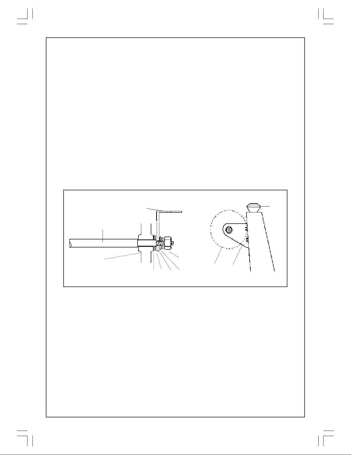
7. Lay the Rip Fence and Cross Cut Guide Bars, together with the two Corner
Supports, alongside the table as shown in fig. 3. The rounded ends of the corner
supports should be attached to the guide brackets, not to the table.
Fig.3
Corner Support
(
R
i
p
G
F
u
e
i
n
d
c
e
(
e
s
B
)
h
a
o
r
r
t
)
Corner Support
(Cross Cut) Guide Bar (long)
With a leg placed in the inside of the corner of the table, insert the screws
through the brackets, table top and leg, using the flat and spring washers
supplied. (i.e. a flat washer next to the screw head, and a flat washer followed
by a spring washer with the nut).
Use the M5 x 20mm screws where the thickness of the guide brackets is to be
taken into account, and M5 x 15mm screws otherwise.
Do not tighten the nuts at this stage - leave them finger tight. The guide brackets
and all four legs should now be loosely bolted in place.
D. Legs and Struts
8. Attach the long and short leg struts to the legs ensuring the screws are entered
in the elongated holes in the struts, with the long strut on top of the short one,
and the open angle of the strut facing you, (i.e. will normally be facing
downwards).
Ensure flat and spring washers are used, as detailed previously.
9
Page 10
9. Attach a rubber foot to each leg, placing a flat washer either side of the hole
in the leg. Screw on the nut and tighten securely.
E. Wheels and Axle Assy
10. In order to install the wheels and axle assembly, first attach all components to
the axle as follows:
Refer to fig 4, and on to each end in turn, thread on:
1. a wheel
2. a 10mm flat washer
3. the axle bracket, with the angle portion facing outwards as shown,
in fig. 4, and the sloping edge downwards towards the foot - as shown
in Fig 4A
4. an 8mm flat washer
5. an 8mm spring washer
6. an M8 nut, which may be tightened securely.
Fig.4
Angle portion facing outwards
Axle
A
BC D
F
E
Fig.4A
A
C
Sloping edge of bracket facing
down towards the foot
Foot
Attach the brackets to the legs, (on the opposite end of the table to that
carrying the short guide bar), with the screws, flat and spring washers provided.
11. With assistance, turn the table to an upright position and rock it vigorously,to
ensure it is completely stable and that no part in under stress. When satisfied,
tighten all nuts systematically starting at the top and working down.
It is recommended that you use gloves during this operation as protection
against the sharp edges that you may encounter.
NOTE:
a. Before tightening the screws securing the guide bar brackets, pull the brackets
apart as far as possible on their elongated holes. (indicated by the arrows in fig
3)
b. For future reference, the FRONT of the table is that end carrying the short guide
bar.
10
Page 11
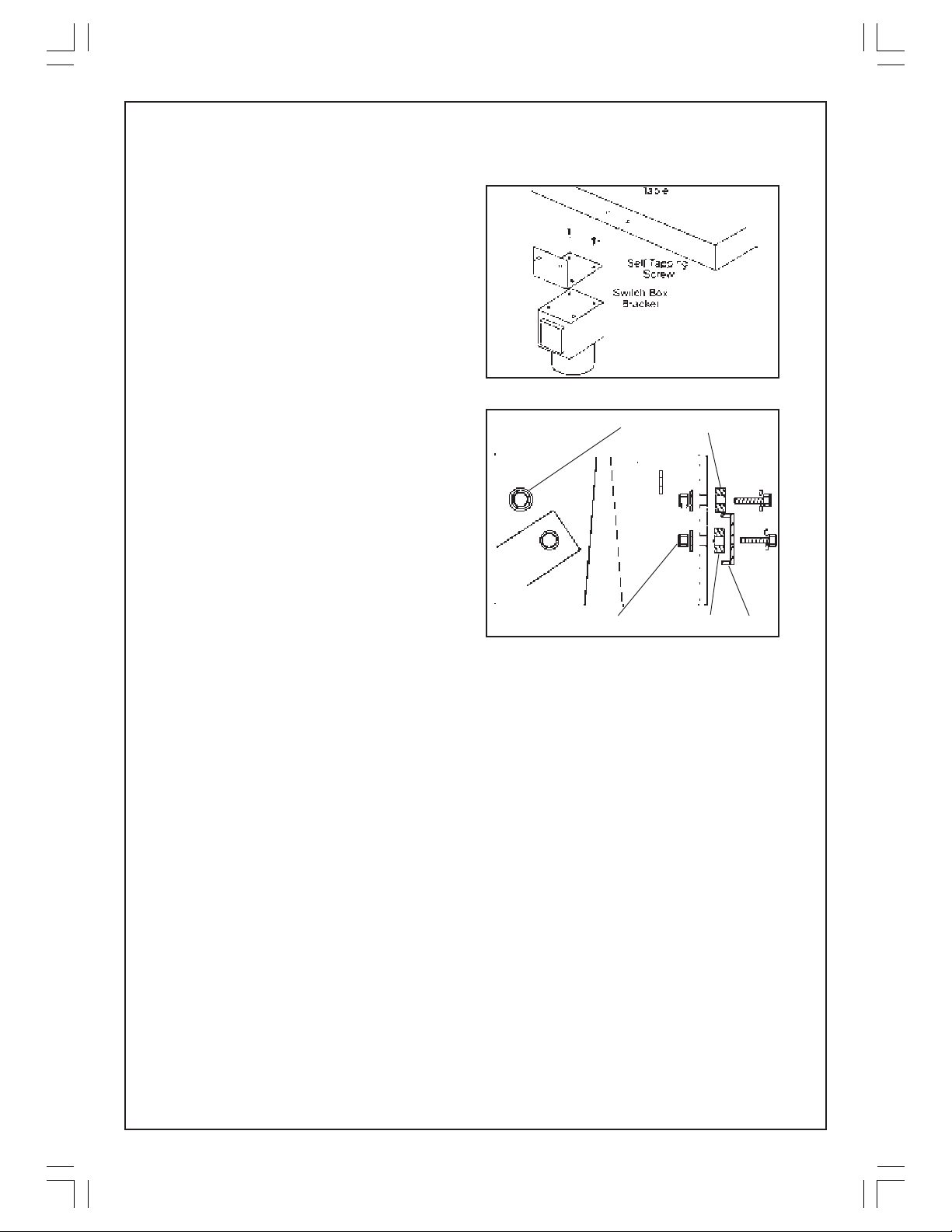
F. Switch Box
12. Attach the switch box to its bracket
using the four 15mm self tapping
screws provided, and attach the
bracket to the Table, in the manner
shown in Fig 5.
Use two 5M x 15mm screws,with nuts,
flat and spring washers provided.
G. Lifting Handles
13. Attach the lifting handles (two
channel sections), to the sides of the
L H Front and R H Front legs,as shown
in fig 6, ensuring flat washers and self
locking nuts are used with the
handle pivot screws. Do not over
tighten the lock nut but allow the
handle to pivot smoothly.
With the Handle Stops, use flat
washers at the screw heads,and flat
and spring washers with the
securing nuts.
Self Locking Nut
Handle StopCollar
Collar
Fig.5
Fig.6
Handle
H. Riving Knife
14. Raise the spring loaded hinged flap beneath the table and open the door to
the lower blade guard box.
Slide the Riving Knife through the slot in the table insert, and locate it on the two
studs on the upper left of the plate carrying the motor assembly, shown in fig 7.
Thread on the 8mm flat washers and M8 self locking nuts, but do not fully tighten
them at this stage.
I. Saw Blade
15. To install the saw blade, it is necessary to remove the Outer Flange and the
Blade Securing Bolt from the motor shaft. To do this, hold the motor shaft, using
a 17mm spanner on the flats milled on the shaft, and unscrew the blade securing
bolt noting that it has a LEFT HAND THREAD.
Locate the saw blade on the shaft, ensuring the blade teeth face down at the
front of the table.
Replace the outer flange, ensuring the flat in its bore engages correctly with
the flat on the motor shaft.
Finally, replace the blade securing bolt, with its spring washer, and tighten it to
approx. 25lbf ft whilst holding the shaft with a 17mm spanner.
11
Page 12
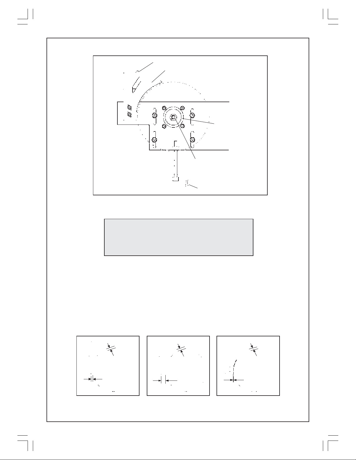
Upper Blade Guard Mounting
Riving Knife
Fig. 7
Outer Flange
Lower Blade
Guard Box
WARNING
Take great care when handling the saw blade.
Blade teeth are extremely sharp, and carelessness
could cause severe injury.
16. With the saw blade in place, the Riving Knife must be adjusted to ensure the
correct clearance is set between it and the saw blade. It is important that this
adjustment is maintained at all times and must be checked regularly.
Adjust the riving knife on its mounting studs so that a gap of 3mm is set between
it and the saw blade around the complete length of the riving knife, as shown
in fig.8.
Blade Securing
Bolt
Blade Height Adjuster
3mm
3mm
✓
Fig.8
3mm
✗
12
3mm
✗
Page 13
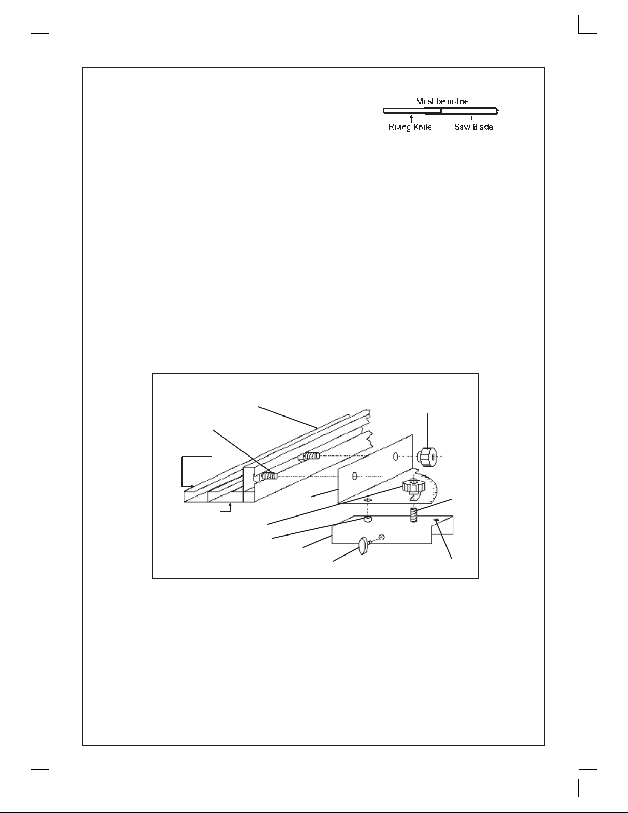
In addition, the riving knife MUST be completely
in line with the saw blade and not bent in any
way.
It may be necessary to place shim washers (not supplied),on to the Riving Knife
mounting studs, between the Riving Knife and the Blade Guard Box, in order to
ensure the Riving Knife is correctly in line with the Saw Blade.
When satisfied,tighten the two self locking nuts to firmly secure the riving nife.
J. Upper Blade Guard
18. Attach the Upper Blade Guard, with its’ single screw, to its mounting on top of
the Riving Knife (shown in fig. 7), ensuring the self locking nut sits snugly in
the recess in the blade guard. Do not over tighten the nut as the blade guard
must pivot and drop easily under its own weight.
K. Rip Fence and Quadrant
19. The Rip Fence may be used in either high or low position and is shown in fig. 9.
With the fence in its lower position (as shown), the work will bear against face
‘A’and in its higher position, face ‘B’.
Fig. 9.
Rip Fence
20mm Screw
RIP FENCE - IN LOW POSITION
Scalloped Hand Wheel
A
Quadrant
Stud
B
Scalloped Hand Wheel
Peg
Rip Fence Support
Rip Fence Support Securing Knob
Lay the fence on the table and slide two M8 x20mm screws into the channel
in the side of the fence as shown.
Position the screws, so that they line up with the holes in the side of the quadrant,
and screw on a large scalloped hand wheel to each screw. This secures the
quadrant to the rip fence.
A channel section - the Rip Fence Support, is then attached to the rip fence
and quadrant sub assembly. This support connects the complete assembly
to either guide bar, depending upon whether you are ripping or cross cutting.
Pointer
13
Page 14
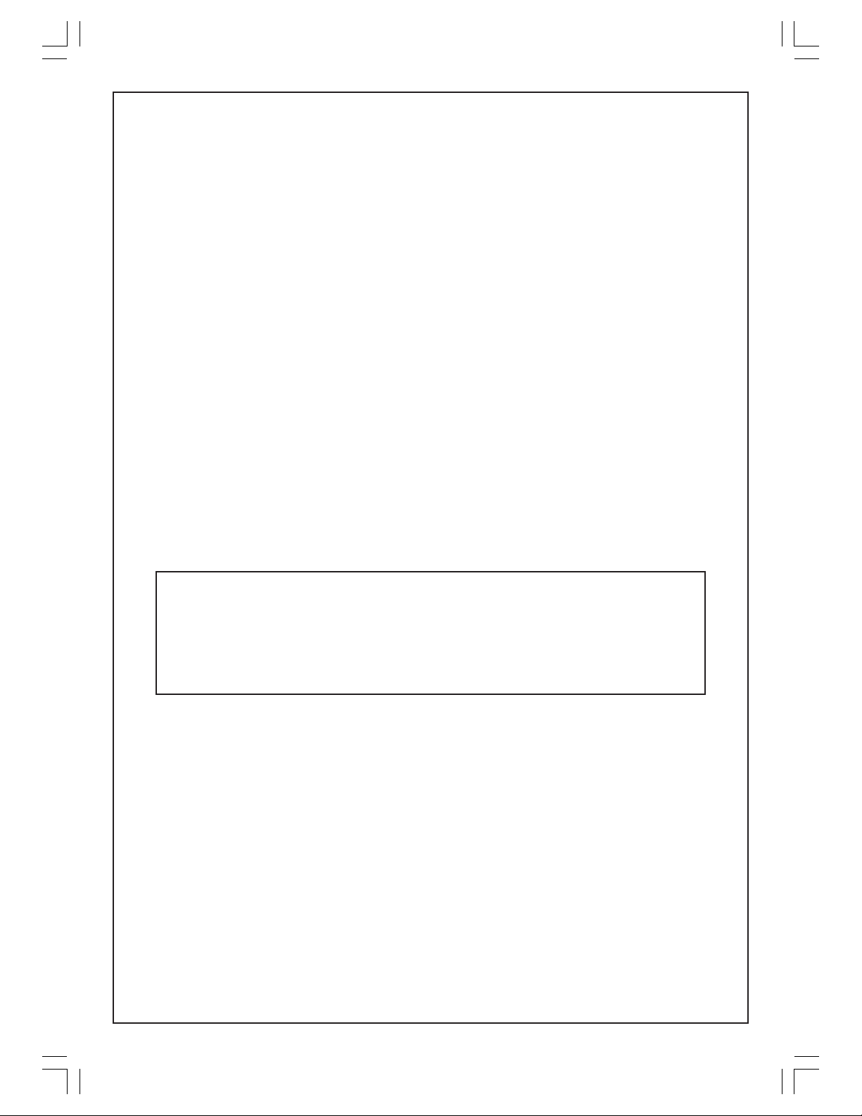
It is attached by pushing the peg and the stud, on the top surface of the
Support, through the holes in the Quadrant, as shown, and screwing a Scalloped
Handwheel on to the stud. A Winged knob is screwed into thethreaded hole in
the side of the Support and is used to secure the complete Rip Fence assembly
to the Guide Bar. This is referrred to as the Rip Fence Support Securing Knob.
To set the Quadrant pointer to zero, slacken off the three hand wheels,
a) two securing the Rip Fence to the Quadrant,
and b) one securing the Quadrant to the Rip Fence Support.
Raise the Upper Blade Guard and move the Rip Fence so that it lies alongside
the saw blade. Tighten all three hand wheels once again when the Rip Fence
is completely parallel to the saw blade. Finally, secure the complete Rip
Fence assembly to the Guide Bar with the Rip Fence Support Securing Knob.
NOTE: If the Rip Fence moves at all, when the Rip Fence Support Securing
Knob is tightened, throwing the Rip Fence out of parallel with the blade, slacken
off the single hand wheel that secures the Quadrant to the Rip Fence Support,
and move the Rip Fence with the Quadrant to compensate for this movement.
Tighten the hand wheel again when completed.
Once satisfied that the Rip Fence is completely parallel to the saw blade,
check the position of the pointer. If necessary, slacken off the pointer securing
screw, zero the pointer and re-tighten the screw.
Your Contractors Saw is now fully assembled.
Before use however, it is important to ensure that all electrical
connections and various adjustments are correctly made in
accordance with the instructions in the following pages.
14
Page 15
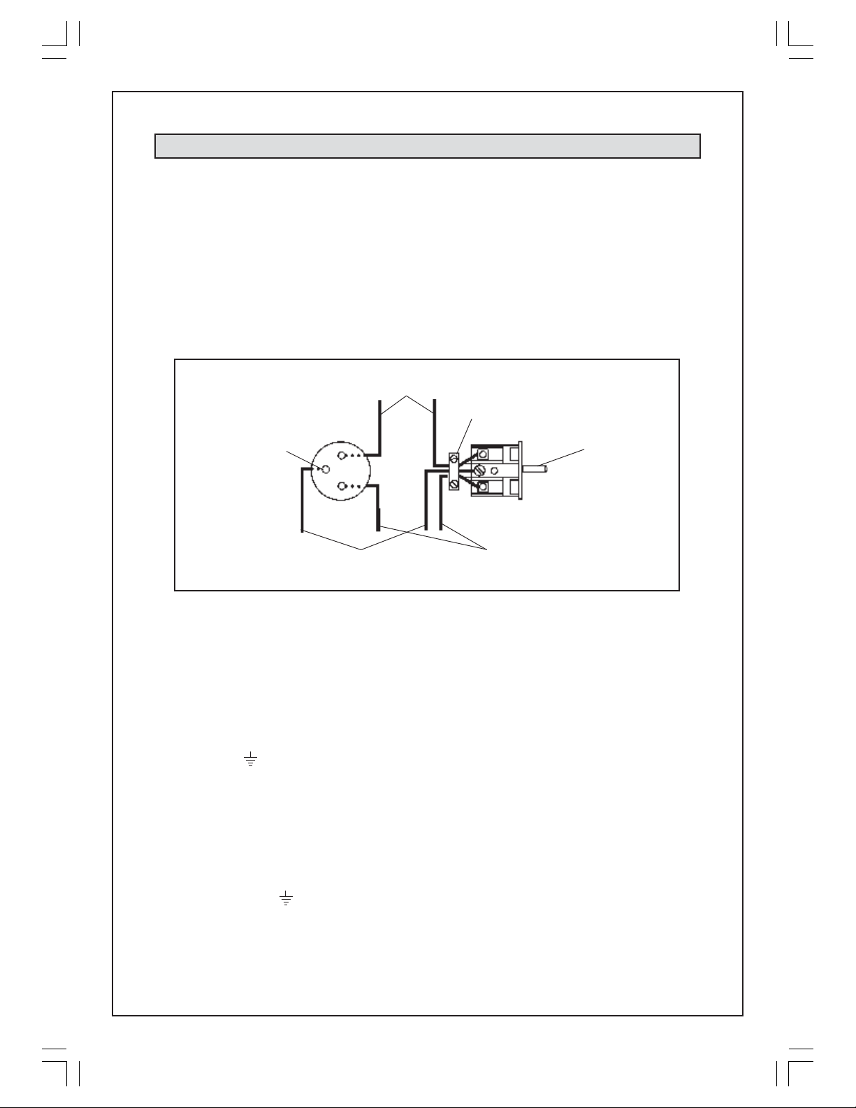
ELECTRICAL CONNECTIONS
WARNING! THIS APPLIANCE MUST BE EARTHED
The Switch Box is provided with a ‘continental’ type trailing socket with an earth pin,
to which a 3-Cord mains power cable should be connected. The minimum cross
section of the conductors in the cable should be 1.5mm2 and the cable type should
be H05VV-F (minimum). The conductor insulation in the cable should be coloured:
Green&Yellow, Blue, and Brown
and should be connected to the trailing socket according to the diagram below.
The Green/Yellow (EARTH) conductor MUST be connected to the single pin, with
the Brown and Blue conductors connected to the terminals indicated.
To disassemble the unit,
remove single screw in
outer rubber shroud and
prise out the socket assy.
EARTH pin
Yellow/Green
conductor
(EARTH)
Blue
conductor
Cable
clamp
Brown
conductor
EARTH pin
Ensure cable clamp
is tightened before
plug is assembled
Ensure the cable clamp is secure and clamps the outer shroud, not the cords.
The other end of the power cable should be connected to a standard 230 Volt
(50Hz) electrical supply, either directly through a suitably fused isolator switch, or
through a normal plug and socket arrangement using an approved 13amp BS
1363 plug.
If a standard 13 amp plug is used,the conductors in the power cable should be
connected as follows:
The GREEN & YELLOW conductor to terminal marked with a letter “E” or Earth
symbol “ “.
The BROWN conductor to terminal marked with a letter “L”.
The BLUE conductor to terminal marked with a letter “N”.
If connecting to a mains supply through a circuit breaker or RCD, the colours of the
conductor insulation may not correspond with the colours in the mains cable from
the trailing socket, in which case, you should proceed as follows. Connect:
The GREEN & YELLOW conductor to the terminal marked with a letter “E” or
Earth symbol “ “ or coloured GREEN or YELLOW & GREEN.
The BROWN conductor to the terminal marked with a letter “L” or coloured RED.
The BLUE conductor to the terminal marked with a letter “N” or coloured BLACK.
We strongly recommend the machine be connected via a residual current device.
15
Page 16
Fuse rating
The fuse in the plug or circuit, must be rated at 13 amps and the plug fuse must be
ASTA or BS approved to BS1362.
Cable extension
If a cable extension is needed, it is essential that it complies with the following
specification.
Extension length Conductor section
Up to 15m 2.5mm
From 15 to 50m 4.0mm
2
2
ADJUSTMENTS
CAUTION
Before carrying out any adjustments, the machine must be disconnected from the
electrical mains supply.
1. Before use for the first time
IMPORTANT:
Before starting your machine for the first time, it is important to ensure that the blade
is central within the Blade Insert, and does not come into contact with the Insert
when tilted to 450.
Tilt the blade to 450 and rotate by hand to ensure there is no contact between it
and the table insert. Should an adjustment be necessary, slacken the nuts
securing the 8 countersunk screws that secure the two Side Brackets to the table
(shown in fig. 2), and move the complete lower guard box and side bracket
assembly so that the blade is:
a. parallel with the edge of the table
b. central within the table insert so that there is no contact between the
blade and insert.
Tighten the nuts securing the 8 countersunk screws when satisfied and recheck.
2. Before each use
IMPORTANT:
Each time you use the machine, you must ensure the components are correctly
adjusted and checked for security BEFOREHAND.
A. For normal ripping or cross cutting, the blade should be exactly square (at 90°),
to the table. To check and adjust, you should proceed as follows:
16
Page 17
1. Raise the blade to its maximum height by using the Blade Height Adjuster
Handle mounted beneath the Lower Blade Guard box.
2. Place a small square on the table and slide it up to the blade. Check to
ensure the blade is square - at 90°.
3. If adjustment is required, slacken off both Blade Tilt Adjuster knobs slightly,
allowing the box to be moved, so that the blade is correctly aligned.
Finally, retighten the adjuster knobs and recheck.
4. When the blade is square, check to ensure the pointer, mounted on the
Lower Blade Guard Box, is pointing to zero. If necessary, slacken off the
pointers’ mounting screw, zero the pointer and retighten the screw.
It should be noted that although an angle gauge is provided so that bevels
up to 45° may be produced, it should not be relied upon for absolute
accuracy. You should always check with a protractor where absolute
accuracy is desired.
B. The Riving Knife is essential in preventing kickback and producing a good clean
cut without chattering or binding taking place.
Before use, check to ensure it is straight and directly in line with the blade,
with the correct clearance of 3mm maintained between it and the blade
along its full length (see fig. 8 on page 12).
Should the Riving Knife become out of shape or misaligned, it must be gently
eased back into line, or if the damage is more severe, it must be removed and
bent back into shape accordingly or replaced.
Adjustment is made by slackening off the two securing nuts (within the Lower
Blade Guard Box), moving the Riving Knife to achieve the correct clearance,
and finally fully tightening the securing nuts.
C. Check to ensure the blade teeth are sharp and the blade is sound. If teeth are
chipped, or cracks are apparent, the blade must be renewed.
D. Always check to ensure that the Lower Blade Guard Box and the Lower Blade
Guard Box Cover are firmly secured.
E. Ensure the Upper Blade Guard is in place, pivots freely, and falls under its own
weight.
OPERATION
1. Rip Cutting
You should always set the depth of the blade to the thickness of the wood plus
2mm. i.e. the blade should only just break the surface of the wood. This is to obtain
maximum efficiency and to protect and preserve the saw blade teeth, particularly
when cutting thin sections.
Blade depth is set by raising or lowering the blade using the adjuster handle mounted
beneath the blade guard box.
17
Page 18

True, straight line rip cutting, is best done by guiding the work against the rip fence.
Ensure the rip fence is set to produce your required width and is parallel to the
blade.
Having taken all the necessary precautions previously stated, plug the machine
into the mains supply, lift the STOP cover on the switch box, and switch ON the
machine by pushing the start button (I).
Proceed to feed the work into the blade but do not force the work - a gentle
pressure is all that is required.
The feed force should ALWAYS be applied between the saw blade and the fence
and down on to the table, NOT on the section that will become the cut-off piece.
ALWAYS use a push stick when the end of the work approaches the blade, or for
short work or work less than 6" wide.
NEVER hold on to the free piece that is cut off. It is important that it is not constrained
in any way - it must be allowed to move laterally.
When switching off, by pushing the stop button (O), the blade should stop within 8
to 10 seconds. Should it take longer, then it will be necessary to adjust or renew the
motor brake pads. In this event, you should consult your CLARKE dealer for advice.
2. Rip Cutting a Bevel.
Set the blade angle by slackening off the two Blade Tilt Adjuster knobs, which secure
the Lower Blade Guard box, and position the blade using the angle gauge and
pointer mounted on the side of the box. (If absolute accuracy is required, check
the blade angle with a protractor)
Fully tighten the adjuster knobs and set the Rip Fence to give the desired width,
before switching ON and feeding the work into the blade.
3. Cross Cutting.
When cross cutting, remember to observe the following additional precautions:
• NEVER touch or hold on to the free piece whilst the saw blade is rotating.
This means that when feeding the workpiece through, you should NOT hold it
on BOTH sides of the blade.
Remember, the free piece should not be constrained in any way. It must be
allowed to move laterally.
• Long pieces of work must be supported at table height, and, the workpiece
must be free to move easily. It is advised to use an assistant for very long
pieces.
Remove the Rip Fence Assembly from the short Guide Bar by slackening off the Rip
Fence Support Securing Knob and lifting it off. Place it on the long Guide Bar as
shown in fig 10.
Slacken off the hand wheel, securing the Quadrant to the Rip Fence Support, and
move the Quadrant, with Rip Fence, to the desired angle as indicated by the pointer.
For normal cross cutting the pointer will be at 0°.
A cross cutting setup for cutting a mitre at 45° is shown in fig. 10. Again, if the angle
is critical, check it with a protractor before tightening the Quadrant securing knob.
18
Page 19
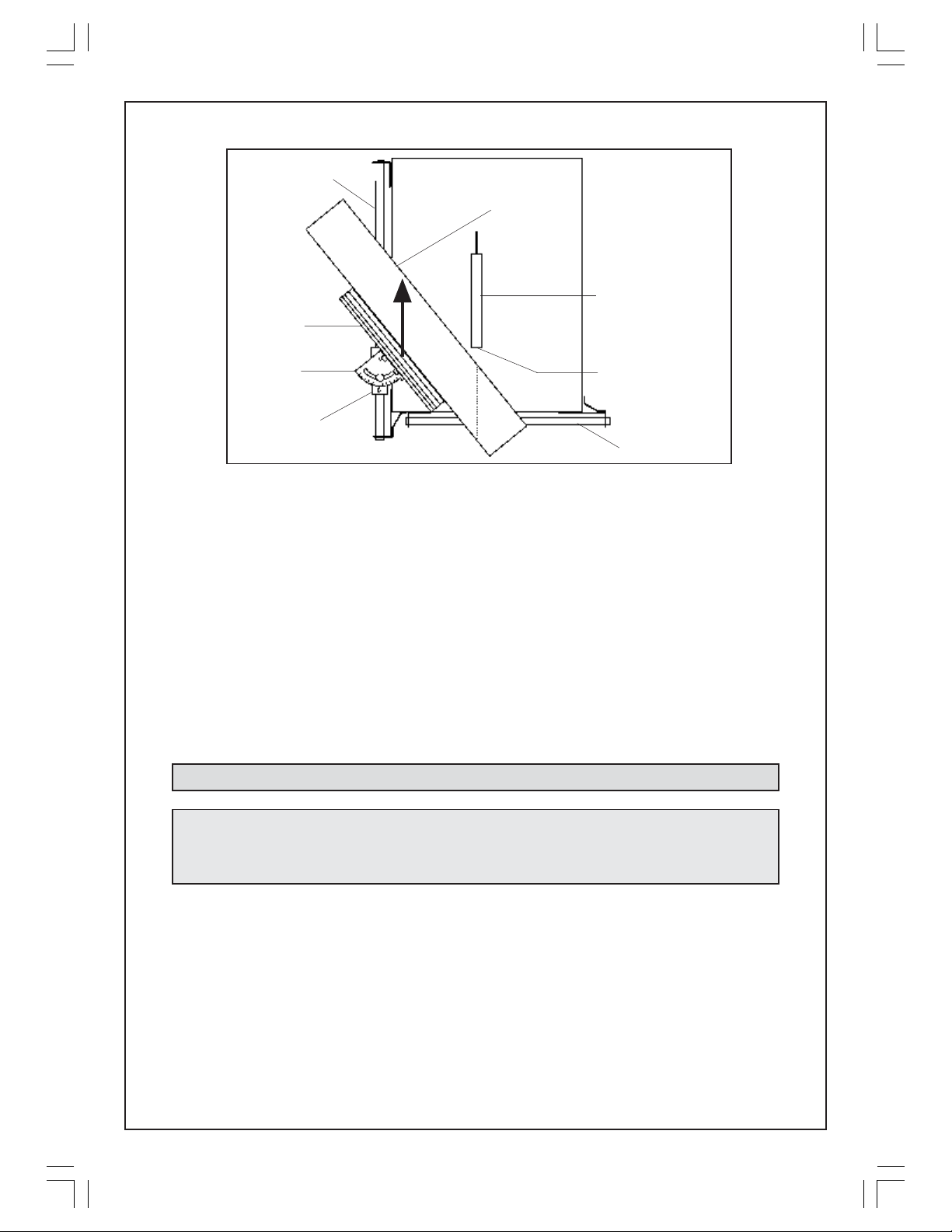
Cross Cut Guide
Rip Fence
Fig 10.
Workpiece
Upper Blade
Guard
Quadrant
Rip Fence
Support Bracket
Saw Blade
Rip Fence Guide
DO NOT tighten the Rip Fence Support Bracket securing knob - leave it loose so
that the Support, with the Rip Fence assembly, may slide along the Guide Bar.
Because the rip fence moves along the guide, towards the saw blade, it is essential
to ensure that it is positioned so that it will not come into contact with the blade.
Before starting therefore, move the complete rip fence assembly along the guide
to check the rip fence position in relation to the saw blade. If necessary, undo the
two hand wheels, securing the rip fence to the quadrant, and re-locate the rip
fence ensuring there will be no contact between the fence and the saw blade.
Tighten the hand wheels when satisfied.
Place the work against the Rip Fence, line up the cut, and, with the machine running,
proceed to cut by sliding the Rip Fence, with the work, along the Guide Bar in the
direction of the arrow, as shown in fig 10.
MAINTENANCE
IMPORTANT :
All maintenance and adjustments must be carried out with the machine
switched OFF, and the power cable disconnected from the mains supply.
1. General
Maintenance is limited to:
• Ensuring the saw blade is kept sharp at all times.(Failure to do so could damage
the motor).
• Changing the saw blade when necessary (see below).
• Maintaining adjustments (as explained on page 15).
• Ensuring that after each use you clean away any sawdust or wood chips with a
low pressure air line or brush. This includes the inside of the Lower Blade Guard
Box.
19
Page 20
Should the motor not function normally, it is possible that it has become clogged
with sawdust, in which case it will be necessary to disassemble the motor in order
to clean the various components. Contact your CLARKE dealer for advice.
2. Changing the Saw Blade
IMPORTANT: Exercise extreme care when handling the saw blade. The teeth are
extremely sharp and careless handling could result in severe personal injury.
2.1 Open the Lower Guard Box door to reveal the saw blade.
2.2 Using a 13mm spanner remove the blade securing bolt, noting that it has a
LEFT HAND THREAD, followed by the outer flange and the saw blade.
NOTE: Flats are milled on the motor shaft, on to which a 17mm spanner may be
fitted, in order to hold the shaft when removing the blade securing bolt.
2.3 Reassemble in reverse order, ensuring:
a. the blade teeth are the correct way round, i.e. facing down at the front of
the table.
b. the flange is correctly mounted, with the flat in the bore of the flange
mating correctly with the flat on the motor shaft.
c. the blade securing bolt is tightened to no more than 25 lbf ft.
2.4 Finally, check to ensure the correct clearance is set between the riving knife
andthe blade. Adjust as necessary (See page 12).
SPECIFICATIONS
Motor - Voltage: 230V 50Hz 1 phase.
Input Current Rating 10 Amps
Fuse Rating 13 Amps
Power Rating: 2.2Kw
Speed: 2,830RPM
Capacitor 25uF 450V
Duty cycle S6 60%
Blade - Size: 12” (300mm) TCT (24 teeth)
Bore 30mm
Noise level Min 88dB Max 115dB
Gross weight 59 kg
Dimensions (at table - incl guides) L900xW710xH800mm (To table top)
Dimensions at base 895x660mm
Max Depth of cut 70mm
Max width of cut with Rip Fence 280mm (high) 220mm (low)
Cross cut mitre angle 0 - 45°
Rip cut bevel angle 0 - 45°
20
Page 21
PARTS LIST
No. Description Qty Part No.
1 Saw Blade 1 AK30501
2 Riving Knife 1 AK30502
3 Upper Blade Guard 1 AK30503
4 Rip Fence 1 AK30504
5 Rip Fence Support 1 AK30505
6 Quadrant 1 AK30506
7 Guide Bar - Long 1 AK30507
8 Guide Bar - Short 1 AK30508
9 Corner Support 2 AK30509
10 Table Insert 1 AK30510
11 Table Top 1 AK30511
12 Legs 4 AK30512
13 Leg Strut - Short 2 AK30513
14 Leg Strut - Long 2 AK30514
15 Handle 2 AK30515
16 Motor Assy. 1 AK30516
17 Switch Box Bracket 1 AK30517
18 Switch Box Assy. 1 AK30518
19 Axle 1 AK30519
20 Wheel 2 AK30520
21 Axle Bracket 2 AK30521
22 Lower Guard Box 1 AK30522
23 Push Stick 1 AK30523
24 Trailing Socket 1 AK30524
25 Tilt Adjuster Knob 2 AK30525
26 Scalloped Knob (F) 3 AK30526
27 Rip Fence Spt Knob 1 AK30527
No. Description Qty Part No.
28 Shouldered Pivot Bolt 2 AK30528
29 Handle Assy 1 AK30529
30 Inner Flange 1 AK30530
31 Outer Flange 1 AK30531
32 Washer 1 AK03032
33 Blade Securing Bolt 1 AK30533
34 Flat Washer 5mm 60 AK30534
35 Spring Washer 40 AK30535
36 Locknut M5 5 AK30536
37 Screw M5x15mm 23 AK30537
38 Screw M5x20mm 13 AK30538
39 Screw M5x25mm 4 AK30539
40 Collar 4 AK30540
41 Bolt M8x20mm 2 AK30541
42 Nut M5 38 AK30542
43 Bolt M5x35mm 1 AK30543
44 Locknut M8 2 AK30544
45 Flat Washer M10 2 AK30545
46 Flat Washer M8 4 AK30546
47 Spring Washer M8 2 AK30547
48 Nut M8 2 AK30548
49 Roll Pin 1 AK30549
50 Hinged Flap 1 AK30550
51 Spring (pair) 1 AK30551
52 Foot 4 AK30552
53 Pan Head Screw 4 AK30553
SPARE PARTS AND SERVICING
For Spare Parts and Servicing, please contact your nearest dealer, or
CLARKE International, on one of the following numbers.
PARTS - 0181 558 6696
SERVICE - 0181 556 4443
PARTS & SERVICE FAX - 0181 558 3622
Please note that the details and specifications contained herein, are correct at the time of going to print. However, CLARKE International reserve
the right to change specifications at any time without prior notice.
21
Page 22
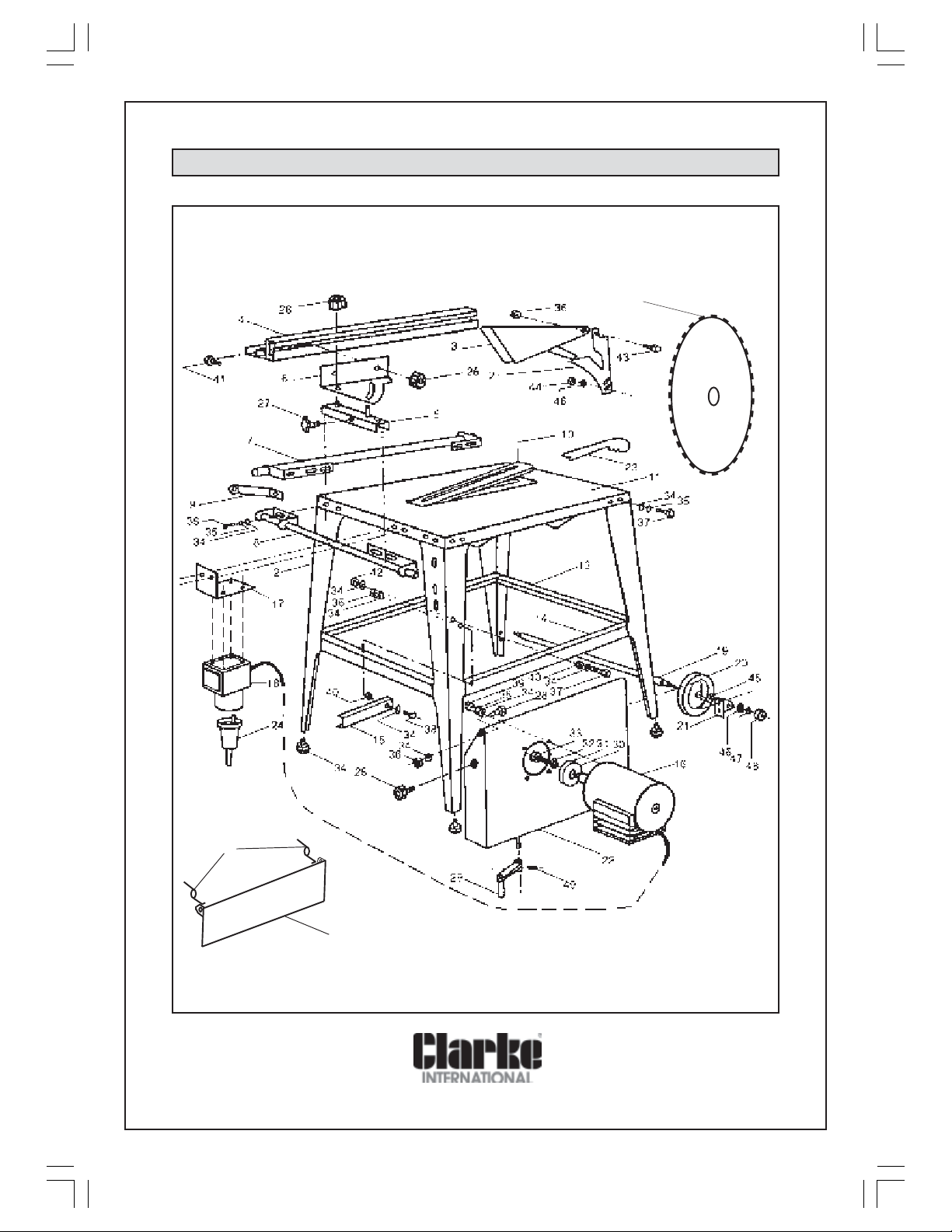
PARTS DIAGRAM
1
5
1
5
0
22
 Loading...