

Page 1
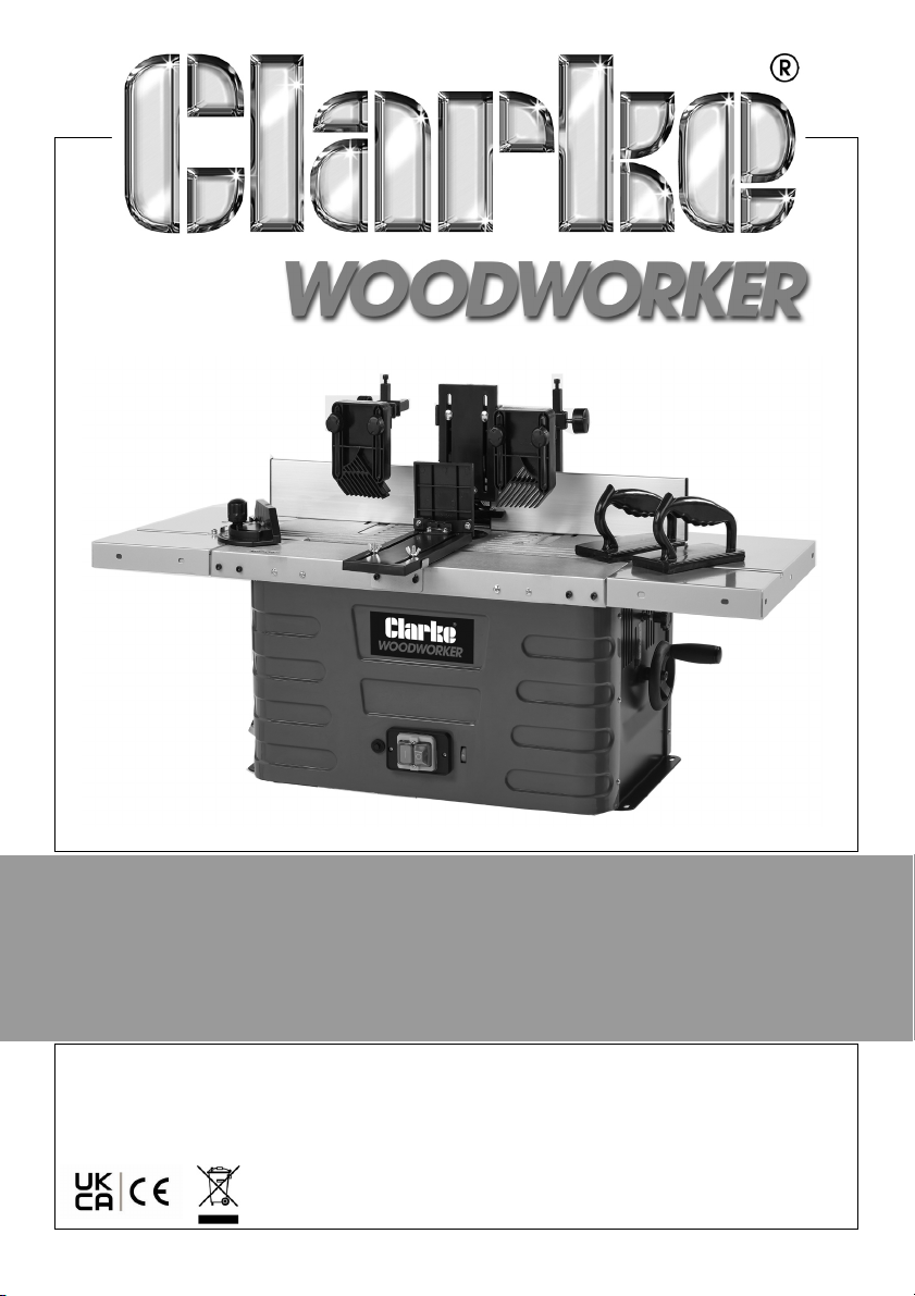
BENCHTOP SHAPER/ROUTER
MODEL NO: CBTSR2
PART NO: 6462091
OPERATION & MAINTENANCE
INSTRUCTIONS
ORIGINAL INSTRUCTIONS
GC04/24 Rev 2
Page 2
INTRODUCTION
Thank you for selecting this Clarke product.
The machine is ideal for shaping wood and plastic and also for cutting out
knots, cutting grooves, removing recesses, copying curves and logos, etc. The
machine must not be used on metal, stone, etc.
Please note that setting up and adjustment of this product ideally requires
some experience of working with this type of equipment.
Save these instructions including all safety warnings and instructions for future
reference.
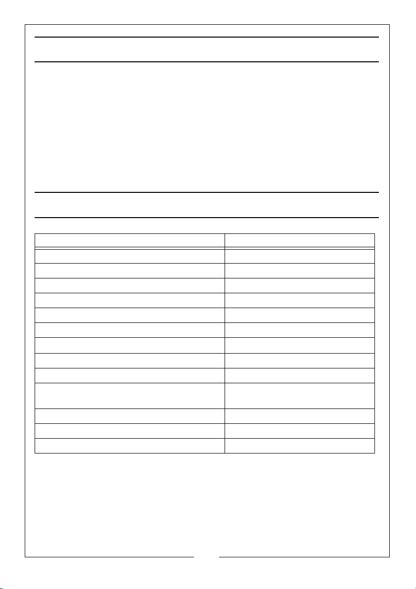
SPECIFICATIONS
Feature Specification
Operating Voltage and Frequency 230V ~ @ 50 Hz
Rated Input Wattage: 1500W
Table Size (with extension) L x W (mm) 1030 x 360 mm
Speeds 11500 rpm to 24000 rpm
Ingress protection rating IP20
Spindle height adjustment 0 - 40 mm
Shank size
Max Dimension of workpiece (L x W x H) 650 x 160 x 65 mm
Table Insert Sizes 32/47/55/75 mm
Dust Extract Adaptor Diameter Outer Dia: 100 mm
Sound Pressure 89 dB (A)
Sound Power Guaranteed LWa 102 dB
Product Weight (Unpacked): 20.9 kg
6/8/12mm and
Inner Dia: 93 mm
¼” / ½”
2
Parts & Service: 020 8988 7400 / E-mail: [email protected] or [email protected]
Page 3

GENERAL POWER TOOL SAFETY WARNINGS
WARNING: READ ALL SAFETY WARNINGS AND ALL INSTRUCTIONS.
FAILURE TO FOLLOW THE WARNINGS AND INSTRUCTIONS MAY RESULT IN
ELECTRIC SHOCK, FIRE AND/OR SERIOUS INJURY.
1. Keep the work area tidy.
• Clutter in the work area can lead to accidents.
2. Take environmental influences into account.
• DO NOT expose power tools to rain.
• DO NOT use power tools in a damp or wet environment.
• Make sure that the work area is well lit.
• DO NOT use power tools where there is a risk of fire or explosion.
3. Protect yourself from electric shock.
4. Keep other persons away.
• DO NOT let persons, especially children, not involved in the work touch
the machine and keep them away from the work area.
5. Securely store unused power tools.
• Unused power tools should be stored in a dry, elevated or enclosed
location out of the reach of children.
6. DO NOT overload your power tool.
• They work better and more safely in the specified output range.
7. Use the correct power tool for the task.
• DO NOT use low-output power tools for heavy work.
• DO NOT use the power tool for purposes for which it is not intended.
8. Wear suitable clothing.
• DO NOT wear loose clothing or jewelry, which can become entangled
in moving parts.
• When working outdoors, anti-slip footwear is recommended.
• Tie back and restrain long hair.
9. Use protective equipment.
• Wear protective eye wear.
• Wear a dusk mask when carrying out dust-creating work.
3
Parts & Service: 020 8988 7400 / E-mail: [email protected] or [email protected]
Page 4

10. Connect the dust extract if you will be processing wood, materials similar to
wood or plastics.
• If connections for dust extraction and a collecting device are present,
make sure that they are connected and used properly.
• When processing wood materials and plastics, operation in enclosed
spaces is only permitted with the use of a suitable extraction system.
11. DO NOT use the power cable for purposes for which it is not intended.
• DO NOT use the power cable to pull the plug out of the socket. Protect
the cable from heat, oil and sharp edges.
12. Secure the workpiece.
• Use clamping devices to hold the workpiece in place as it is held more
securely than with your hand.
• An additional support is necessary for long workpieces (table, trestle,
etc.) in order to prevent the machine from tipping over (if not bolted
down).
• Always press the workpiece firmly against the working plate and fence
in order to prevent bouncing and twisting of the workpiece.
13. Avoid abnormal posture.
• Make sure that you have secure footing and always maintain your
balance.
• Avoid awkward hand positions in which a sudden slip could cause one
or both hands to come into contact with the cutter bit.
14. Take care of your tools.
• Keep cutting tools sharp and clean in order to be able to work better
and more safely.
• Check the power cable of the power tool regularly and have it
replaced by a recognised specialist if damaged.
• Check extension cables regularly and replace them if damaged.
• NEVER remove loose splinters, chips or jammed wood pieces from the
cutter bit until it has stopped.
• If the cutter bit is blocked due to abnormal feed force during cutting,
turn the machine off and remove the work piece. Ensure that the cutter
bit runs freely. Turn the machine back on and start a new cutting
operation with less feed force.
15. Before switching on, make sure that any adjusting tools are removed.
16. Avoid inadvertent starting.
4
Parts & Service: 020 8988 7400 / E-mail: [email protected] or [email protected]
Page 5

• Make sure that the machine is switched off when inserting the plug into
a power outlet.
17. Stay alert.
• Pay attention to what you are doing. DO NOT use the power tool when
you are distracted, tired, or under the influence of drugs or alcohol.
18. Check the power tool for potential damage.
• Protective devices and other parts must be carefully inspected to
ensure that they are fault free and function as intended prior to
continued use of the power tool.
• Check whether the moving parts function faultlessly and do not jam or if
parts are damaged. All parts must be correctly mounted and all
conditions must be fulfilled to ensure fault free operation of themachine.
• Damaged protective devices and parts must be properly repaired or
replaced.
• DO NOT use faulty or damaged connecting cables.
• DO NOT use apower tool if the switch cannot be switched on and off.
19. The use of other accessories than recommended items can have a risk of
injury.
20. Have your power tool repaired by a qualified electrician.
• This power tool conforms to the applicable safety regulations. Repairs
may only be performed by an electrician using original spare parts or
accidents could occur.
21. The operator must always stand in front of the machine while working.
ADDITIONAL SAFETY INSTRUCTIONS FOR ROUTERS
1. Check that cutting bits are in perfect condition before use.
2. Use table insert rings appropriate for the size of the cutting bits.
3. ALWAYS wear suitable personal protective equipment including:
• Hearing protection to avoid the risk of becoming hearing impaired.
• Respiratory protection to avoid the risk of inhaling harmful dust.
• Safety goggles to avoid eye injuries due to flying particles.
4. Beware of injury when handling bits and materials with sharp edges.
5. When working with wood, beware of conditions that cause the release of
dust, e.g. the type of material to be processed and the correct setting of
the hood/guide plates/guides.
6. Support long workpieces sufficiently to hold their position.
5
Parts & Service: 020 8988 7400 / E-mail: [email protected] or [email protected]
Page 6
7. Take care of possible rebound due to any guide for a small workpiece
being unsuitable.
8. Use additional equipment when processing narrow workpieces.
9. Tools that have not been maintained can trigger uncontrollable situations.
Only use sharp, well maintained cutting bits.
10. Before changing cutting bits or making adjustments, switch off the
machine.
11. Select a rotational speed that is suitable for the cutting bit and work
material used.
RESIDUAL RISKS
The machine is built according to current and recognized safety regulations.
Nevertheless residual risks can occur during work.
• Danger of injury to fingers and hands by the tool due to inappropriate
guidance of the work piece.
• Injuries caused by a work piece flying off due to lack of restraint or
guidance.
• Health hazards due to wood dust or wood chips. Wear personal
protection equipment such as eye protection. Use a ventilation system.
• Injuries by defective tools. Examine the tool regularly for soundness.
• Danger of injury to fingers and hands during tool changes. Wear suitable
working gloves.
• Danger of injury when switching on the machine.
• Hazards due to current by use of incorrect electrical connecting cables.
• Residual risks can be minimized if the safety instructions and operating
instructions are followed in full.
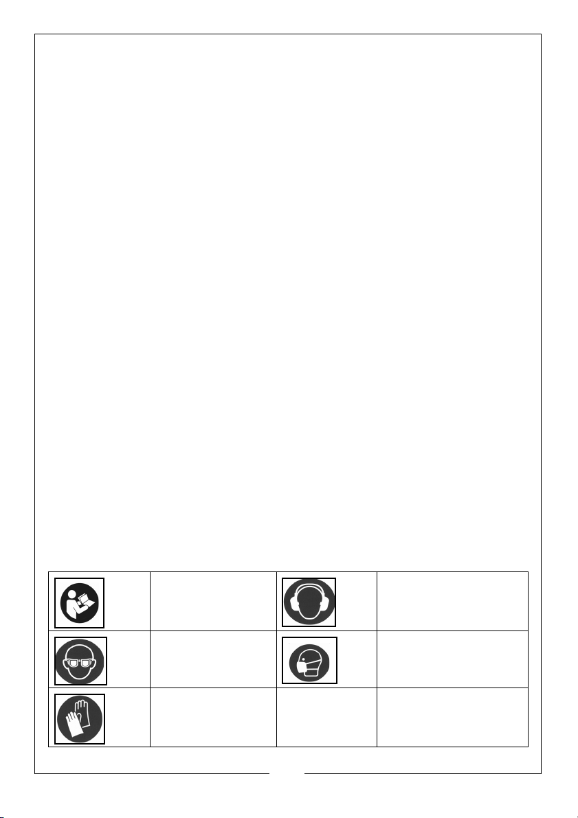
SAFETY SYMBOLS ON THE MACHINE OR PACKAGING
Read instruction
manual before
use
Wear safety
glasses
Wear protective
gloves
6
Parts & Service: 020 8988 7400 / E-mail: [email protected] or [email protected]
Wear ear defenders
Wear a breathing
mask.
Page 7
ELECTRICAL CONNECTIONS
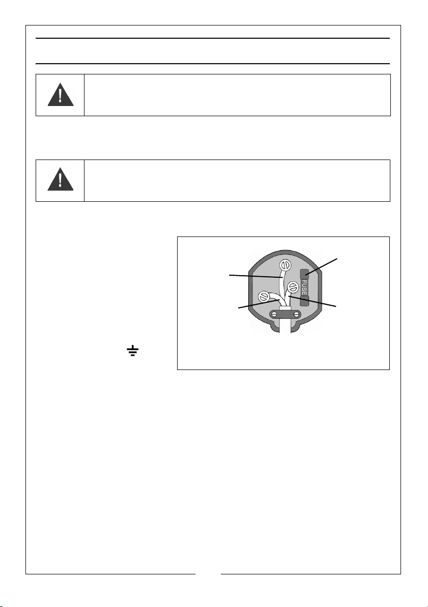
Plug must be BS1363/A approved.
Always fit
Ensure that the outer sheath of
Neutral
(Blue)
Live
(Brown)
Earth
(Green and
a 13 Amp
the cable is firmly held by the clamp
fuse.
Yel low)
WARNING! READ THESE ELECTRICAL SAFETY INSTRUCTIONS FULLY
BEFORE CONNECTING THE MACHINE TO THE MAINS SUPPLY.
This machine is provided with a standard 13 amp, 230 volt (50Hz), BS 1363 plug,
for connection to a standard, domestic electrical supply. Should the plug
need changing, make sure that a plug of identical specification is used.
WARNING! THE WIRES IN THE POWER CABLE OF THIS PRODUCT
ARE COLOURED IN ACCORDANCE WITH THE FOLLOWING CODE:
BLUE = NEUTRAL BROWN = LIVE YELLOW AND GREEN = EARTH
If the colours of the wires in the power cable do not agree with the markings
on the plug:
• Connect the blue wire
to the terminal which
is marked N.
• Connect the brown
wire to the terminal
which is marked L.
• Connect the yellow
and green wire to the
terminal which is
marked E or
We strongly recommend that this machine is connected to the mains supply
through a Residual Current Device (RCD)
If you are not sure, consult a qualified electrician. DO NOT try to do any
repairs.
CABLE EXTENSIONS
Always use an approved cable extension suitable for the power rating of this
machine. The conductor size should also be at least the same size as that on
the machine, or larger.
Parts & Service: 020 8988 7400 / E-mail: [email protected] or [email protected]
7
Page 8

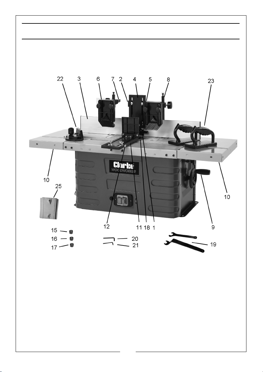
INVENTORY
The following items are supplied for fitting/assembly.
1. Fence (52)
2. Sliding Bracket (64)
3. Fence Plate (66)
4. Downwards Pressure Bar (63)
5. Mounting Bracket for the above (56)
6. 2 x Pressure Pads (68)
7. Square Mounting Plates (61)
8. Square Supports (60)
9. Elevating Handle (31)
10. Table Extensions (41 & 71)
11. Kickback Safety Fence (103)
12. Mounting Bracket for the above (104)
13. Dust Extractor Adaptor (53) - (not shown)
14. Transparent Tool Guard (50) - (not shown)
15. 6mm Collet (78)
16. 8mm Collet (77)
17. 12 mm Collet
18. Table Insert Rings (49)
19. Spanners (73)
20. 3mm Hex Key (74)
21. 4mm Hex Key (75)
22. Mitre Fence (99)
23. Push Blocks (72)
24. Fixings Packs
25. Table extension alignment bracket
Numbers in brackets refer to pages 26-29.
8
Parts & Service: 020 8988 7400 / E-mail: [email protected] or [email protected]
Page 9
COMPONENT INVENTORY
9
Parts & Service: 020 8988 7400 / E-mail: [email protected] or [email protected]
Page 10
ASSEMBLY
MOUNTING THE MACHINE
It is recommended to fix the machine to a workbench using the four holes
provided.
• Holes must be drilled in the workbench which align with those on the
machine base.
• Each corner must be secured to the workbench using nuts and bolts
long enough to go through the workbench (not supplied).
• The workbench must be large enough to prevent tilting of the machine
when working.
ASSEMBLING THE FENCE
Before starting work the fence must be assembled and fitted to the work
table.
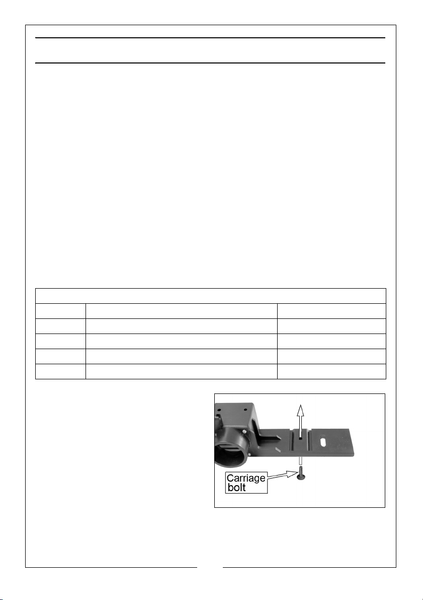
FITTING THE SLIDING BRACKET TO THE FENCE
Parts needed for this step
1 x Fence
1 x Sliding bracket
1 x Carriage bolt M6 x 25
1 x Plastic cap nut M6
1 x Washer 6mm
1. Insert the carriage bolt into the
fence from below as shown.
10
Parts & Service: 020 8988 7400 / E-mail: [email protected] or [email protected]
Page 11
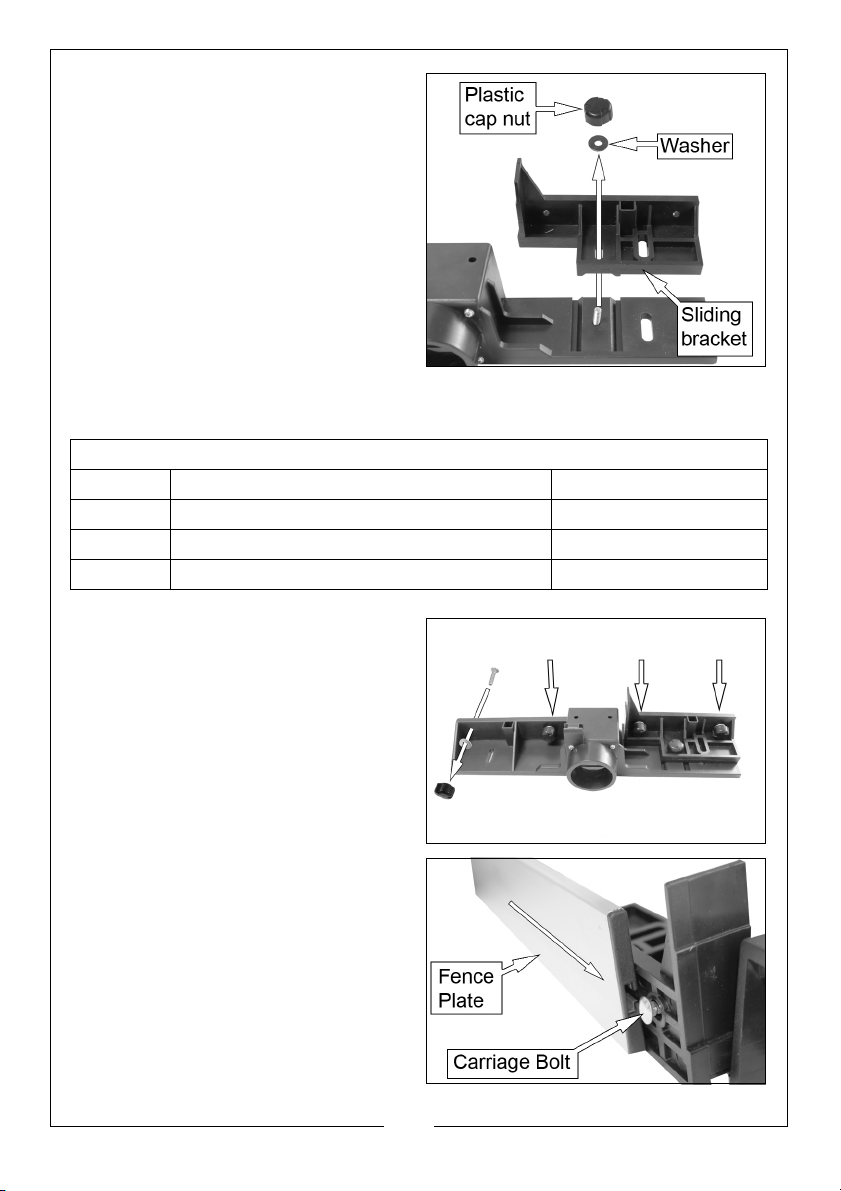
2. Drop the sliding bracket over the
bolt so that it sits in the grooves on
the fence.
3. Secure in place using the washer
and plastic cap nut.
FITTING THE FENCE PLATES
Parts needed for this step
4 x Carriage bolt M6 x 20
4 x Plastic cap nut M6
4 x Washers 6mm
2 x Fence plates
1. Insert the 4 carriage bolts into the
attachment holes and screw
them on finger tight with a washer
and a plastic cap nut.
2. Slide the fence plates over the
carriage bolt heads.
• Make sure that the fence
plates are at the same height.
3. Tighten the plastic cap nut to lock
the fence plates in position.
11
Parts & Service: 020 8988 7400 / E-mail: [email protected] or [email protected]
Page 12
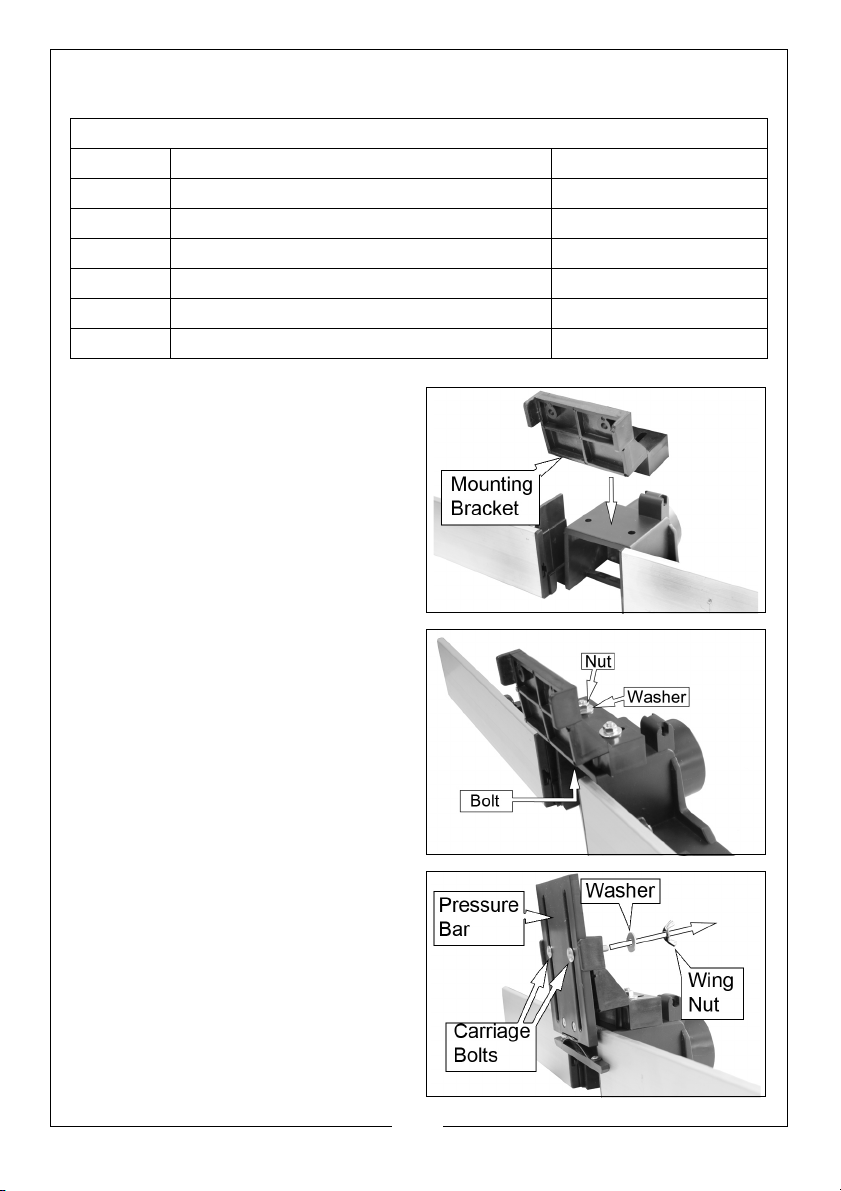
FITTING THE DOWNWARD PRESSURE BAR
Parts needed for this step
1 x Mounting Bracket
2 x Bolt M6 x 40
2 x Nut M6
4 x Washers 6mm
1 x Pressure Bar
2 x Carriage Bolts M6 x 35
2 x Wingnuts M6
1. Fit the mounting bracket to the
central part of the main fence as
shown.
2. Secure in place using 2 x M6 x 40
bolts (from below), 2 washers and
2 x M6 nuts supplied.
3. Position the pressure bar and lock
in position using the 2 carriage
bolts, 2 washers and 2 wing nuts
provided.
12
Parts & Service: 020 8988 7400 / E-mail: [email protected] or [email protected]
Page 13
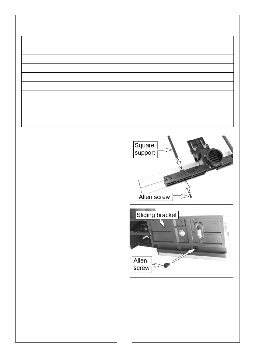
FITTING THE PRESSURE PADS
Parts needed for this step
2 x Pressure pads
2 x Square mounting plate
2 x Square supports
2 x Clamp
2 x Allen screws M6 x 16
2 x Plastic cap screws M6 x 20
4 x Carriage bolts M6 x 35
4 x Plastic cap nuts M6
4 x Washers 6mm
1. Insert the 2 square supports in the
2 square sockets on the main part
of the fence.
2. Secure them with the 2 Allen
screws from below.
NOTE: You will need to slide the
sliding bracket forward to
gain access to one of the
holes.
13
Parts & Service: 020 8988 7400 / E-mail: [email protected] or [email protected]
Page 14
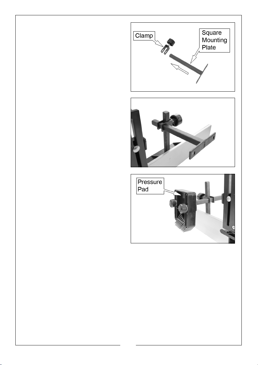
3. Slide the square mounting plate
into the clamp as shown.
4. Slide the clamp over the square
support as shown.
5. Secure in place by tightening the
knob on the clamp. Repeat for
the other assembly.
6. Fit the pressure pads to the square
mounting plates using 4 carriage
bolts, 4 washers and 4 plastic cap
nuts.
14
Parts & Service: 020 8988 7400 / E-mail: [email protected] or [email protected]
Page 15
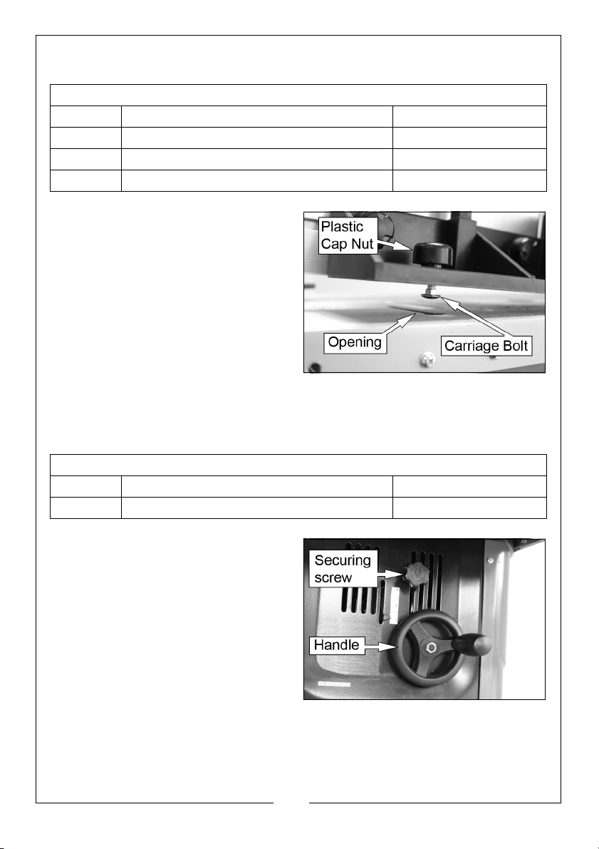
FITTING THE FENCE ONTO THE WORKING TABLE
Parts needed for this step
1 x Carriage bolt M6 x 20
1 x Carriage bolt M6 x 40
2 x Plastic cap nuts M6
2 x Washers 6mm
1. Fix the 2 plastic cap screws into
the grooves in the fence using the
washers and carriage bolts as
shown.
• The longer carriage bolt goes
on the right, when viewing the
fence from the rear.
2. Put the tops of the carriage bolts
through the opening in the table.
3. Position the fence as required and
tighten the plastic cap nuts.
FITTING THE HANDLE
Parts needed for this step
1 x Handle
1 x Nut (already fitted) M8
1. Slide the handle over the shaft
making sure it engages with the
pin.
2. Secure in place using the nut.
15
Parts & Service: 020 8988 7400 / E-mail: [email protected] or [email protected]
Page 16
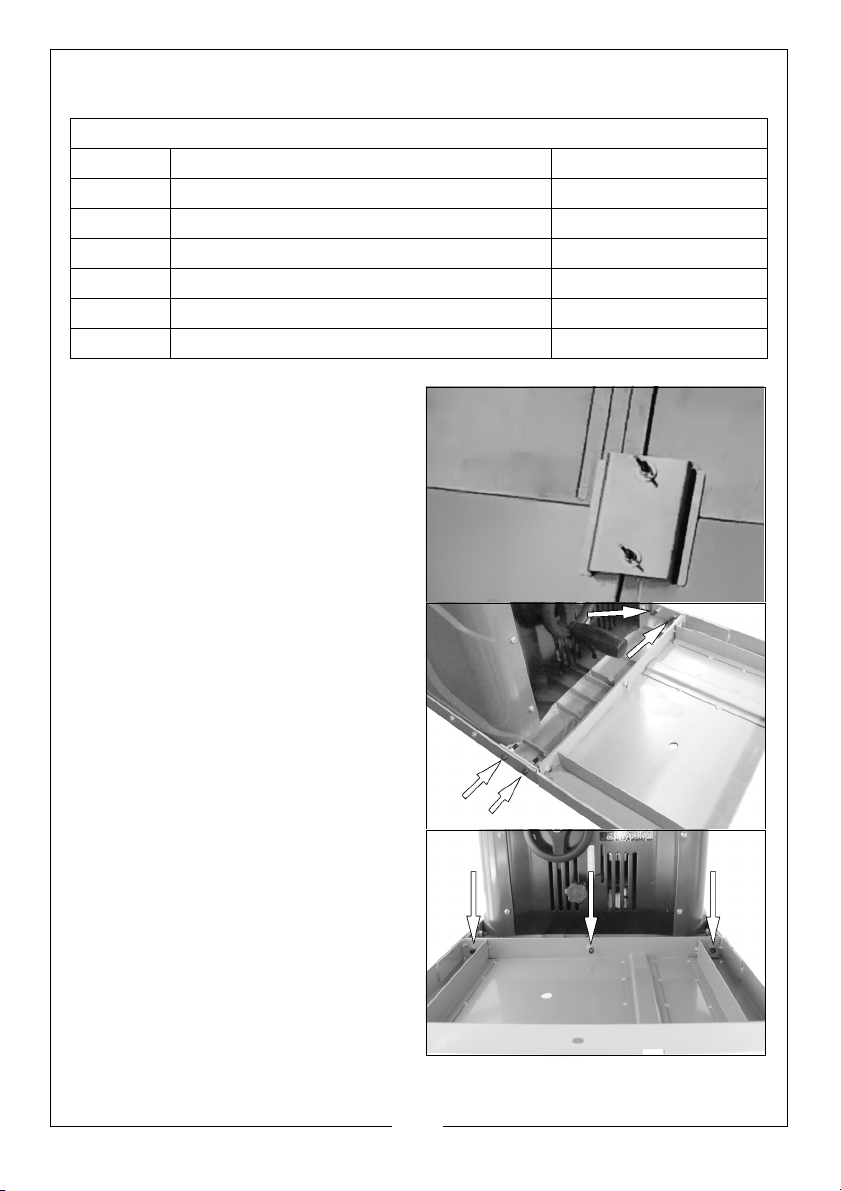
FITTING THE TABLE EXTENSION
Parts needed for this step
2 x Table extensions
1 x Table alignment tool
8 x Allen screws M5 x 20
6 x Allen screws M5 x 12
14 x Washers 5mm
8 x Hexagonal nyloc nuts M5
6 x Spring washers 5mm
1. Remove the fence and use the
table alignment tool to
accurately position the table
extension for assembly. Tighten
the wingnuts to secure in position.
2. Flip the unit upside down onto a
smooth flat surface.
3. Attach the extension table to
both sides with 4 allen screws M5 x
20, 4 washers and 4 hexagonal
nyloc nuts M5.
4. Also secure using 3 allen screws
(M5 x 12), 3 washers and 3 spring
washers each.
5. Align the table and tighten all
screws.
6. Repeat for the other table
extension.
7. Flip the unit the right way up
again (with assistance if required).
Remove the alignment bracket
and replace the fence.
16
Parts & Service: 020 8988 7400 / E-mail: [email protected] or [email protected]
Page 17
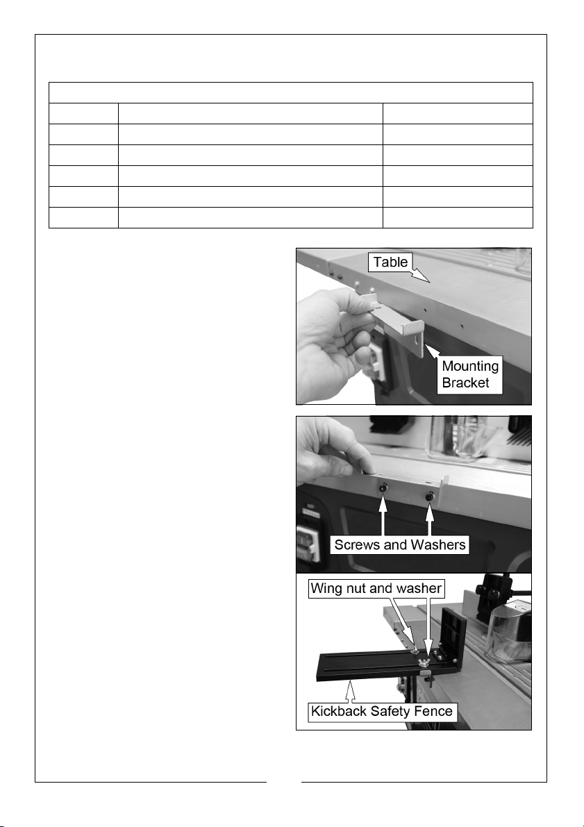
FITTING THE KICKBACK SAFETY FENCE
Parts needed for this step
1 x Kickback safety fence
1 x Mounting bracket
2 x Cross head screws with washers M5 x 10
2 x Carriage bolts M6 x 25
2 x Washers 6mm
2 x Wing nuts M6
1. Align the mounting bracket with
the two holes on the front of the
table.
2. Insert the two cross head screws
with washers into the holes and
tighten.
3. Install the kickback safety fence
• You can adjust the fence to the
thickness of the work piece.
4. After setting, fix it in place with the
help of the two carriage bolts, 2
washers and 2 wing nuts.
17
Parts & Service: 020 8988 7400 / E-mail: [email protected] or [email protected]
Page 18
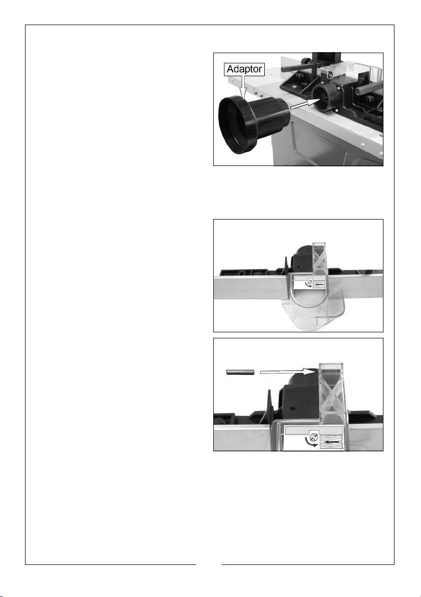
CONNECTING TO A DUST EXTRACTOR
Slide the suction hose of the dust
extractor unit onto the dust
extraction port at the rear of the
moulding fence.
• For hoses with a dia of 100 mm,
using the adapter supplied.
FITTING THE TRANSPARENT TOOL GUARD
1. Remove downward pressure bar and bracket shown on page 12.
2. Place transparent tool guard in
position as shown.
3. Insert pin to secure.
• Check to see the guard
functions correctly before use.
18
Parts & Service: 020 8988 7400 / E-mail: [email protected] or [email protected]
Page 19
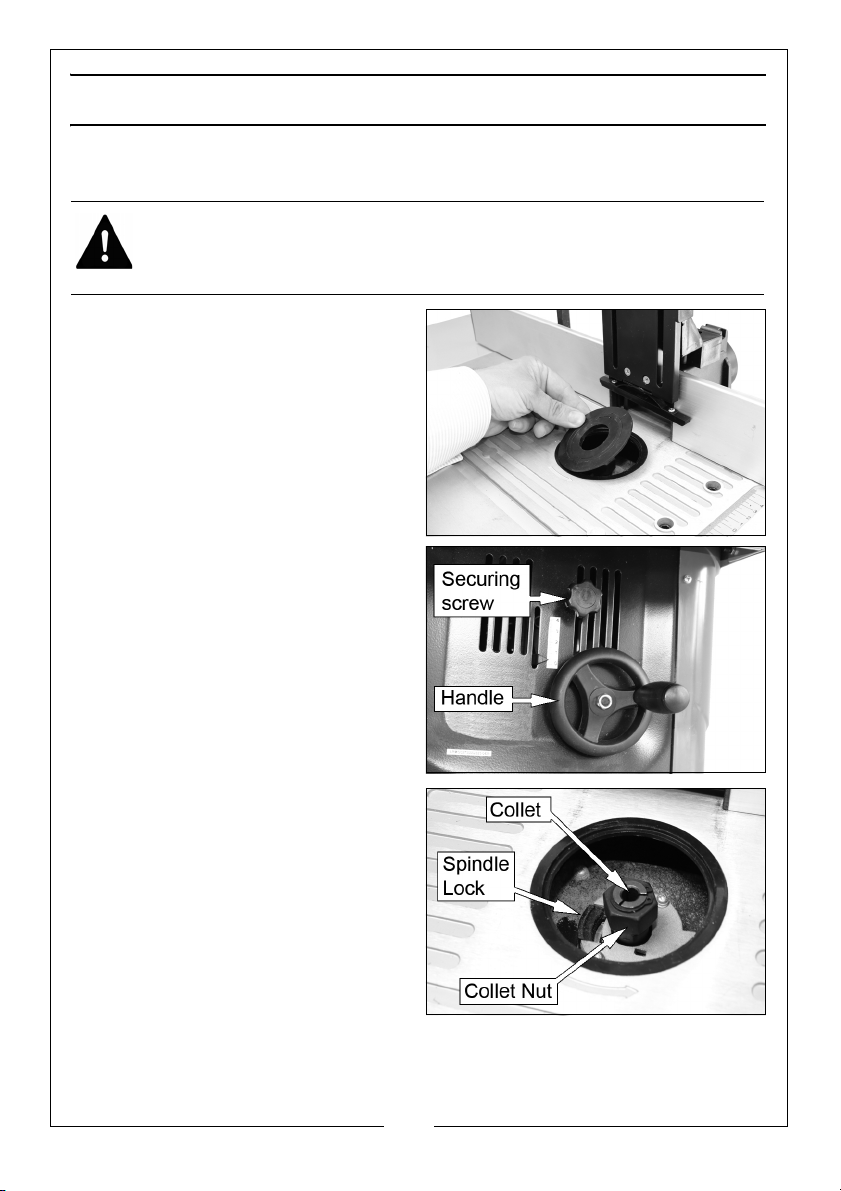
BEFORE USE
INSTALLING AND CHANGING THE COLLETS AND CUTTING BITS
WARNING: BEFORE CARRYING OUT ANY ADJUSTMENT OR
MAINTENANCE, MAKE SURE THAT THE MACHINE IS DISCONNECTED FROM
THE MAINS SUPPLY.
1. Remove the insert rings from the
table.
2. Loosen the securing screw and
use the handle to raise the spindle
to its highest position.
3. Press and hold the Spindle Lock
button.
19
Parts & Service: 020 8988 7400 / E-mail: [email protected] or [email protected]
Page 20
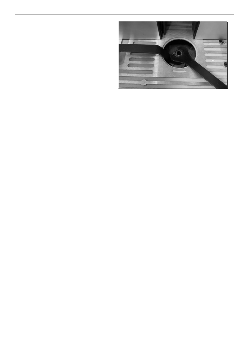
4. Loosen the collet nut using the
spanners provided and
remove the cutting bit and
collet nut if required.
5. Insert the required collet/collet
nut and tighten it slightly.
6. Insert the bit into the collet.
• At least 3/4 of the cutting bit
shank must be gripped in
the collet before tightening.
7. Press and hold the spindle lock button and tighten the collet nut securely.
• Before every use of the machine make sure that the cutting bit is secure.
8. Place the insert rings back in to their original position.
• The insert rings must be used in order to keep the spacing between table
and cutter to a minimum. Only fit enough insert rings so as to allow the
bit to come through the surface of the table without touching the rings.
• Before switching on check the insert rings are seated correctly.
9. Reconnect the machine to the power supply.
20
Parts & Service: 020 8988 7400 / E-mail: [email protected] or [email protected]
Page 21
ADJUSTMENTS
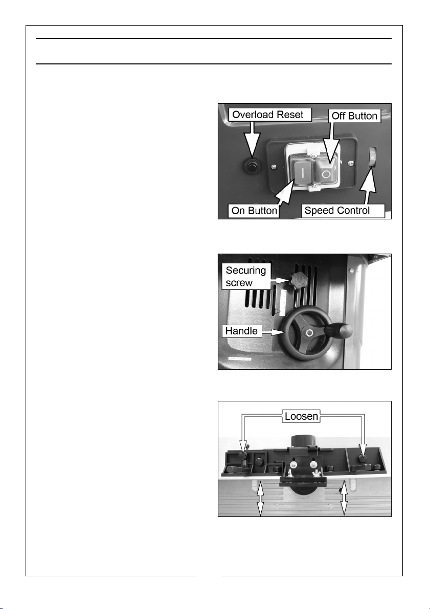
SPEED CONTROL
The speed control has 6 speeds.
Determine the optimal setting by
testing on a scrap piece of wood.
NOTE: The use of the correct setting
will increase the life-span of
the cutter. It, also affects the
quality of the cut.
RAISING/LOWERING THE CUTTER
To raise or lower the spindle height.
1. Loosen the securing screw.
2. Use the handle to raise or lower
the spindle to the required height.
3. Tighten the securing screw.
ADJUSTING THE FENCE
1. Loosen the plastic cap screws
shown on the back of the fence.
2. Move the fence to the desired
position.
3. Re-tighten the plastic cap screws
to keep the fence in this position.
21
Parts & Service: 020 8988 7400 / E-mail: [email protected] or [email protected]
Page 22
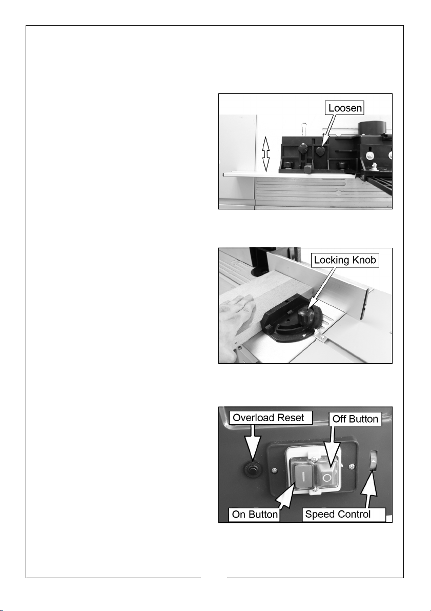
OUTFEED FENCE OFFSET
Once the workpiece passes the cutting bit it may be thinner then when it
started. If so you should adjust the left fence to compensate for the missing
material.
1. Loosen the plastic cap screws.
2. Move the left fence towards you
slightly and tighten the plastic cap
screws.
ADJUST THE CROSS-CUTTING JIG
1. Loosen the locking knob.
2. Set the jig to the desired angle.
3. Tighten the locking knob.
• Always make a sample cut in a
piece of waste material in
order to guarantee the angles
are correct.
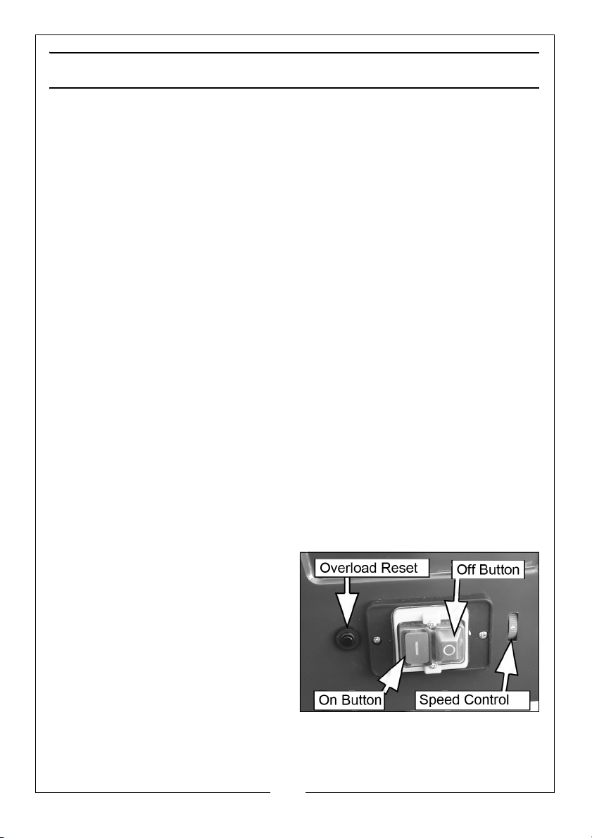
SWITCHING ON AND OFF
• Press the green ON (I) button to
start the machine.
• Press the red OFF (O) button to
stop the machine.
22
Parts & Service: 020 8988 7400 / E-mail: [email protected] or [email protected]
Page 23
USING THE MACHINE
1. Insert an appropriate cutting bit.
2. Adjust the machine speed and adjust the fence so that the material is
supported along its entire length.
3. Switch the machine on by pressing the green ON (I) button.
4. Make sure the workpiece is firmly pressed against the fence.
5. Push the work piece softly from right to left against the turning direction of
the cutting bit.
• Keep your speed constant. DO NOT push too fast as it would slow down
the motor.
• Feeding the work piece too fast will result in poor cutting quality. There is
also the risk of damaging the cutting bit or the machine motor.
• Feeding the work piece too slowly will result in burnt spots on the work
piece.
• The correct intake speed depends on the cutting bit size, the material
type of the workpiece and the cutting depth. It is recommended to
practice first with a piece of scrap wood in order to determine the
correct speed.
6. With very hard wood and important cuts it may be better to work
progressively, taking several shallow cuts until the desired depth is
achieved.
7. Switch the machine off by pressing the red OFF (O) button.
OVERLOAD SWITCH
The machine is fitted with an
overload switch to protect the motor.
In the event of an overload situation,
the machine will cut out
automatically.
After a short time press the overload
reset button to reset the machine.
23
Parts & Service: 020 8988 7400 / E-mail: [email protected] or [email protected]
Page 24

MAINTENANCE AND SERVICING
WARNING: BEFORE CARRYING OUT MAINTENANCE, MAKE SURE THAT THE
MACHINE IS DISCONNECTED FROM THE MAINS SUPPLY.
CLEANING
• Keep all safety devices, air vents and the motor housing free of dirt and
dust. Wipe the equipment with a clean cloth or blow it with compressed
air at low pressure (always wear PPE when using compressed air).
• We recommend that you clean the machine as soon as you have
finished using it.
• DO NOT use cleaning agents or solvents as these could attack the
plastic parts of the machine.
• Make sure that no water can enter the machine. The ingress of water
into a power tool increases the risk of an electric shock.
CUTTING BITS
• Any resin must be cleaned off the cutting bits at regular intervals with an
appropriate resin remover.
STORAGE
• Store the machine and accessories out of children’s reach in a dark, dry
place at above freezing temperature. The ideal storage temperature is
between 5 and 30°C.
• Ideally, store the machine in its original packaging.
• Cover the machine in order to protect it from dust and moisture.
• Store the operating manual with the machine.
24
Parts & Service: 020 8988 7400 / E-mail: [email protected] or [email protected]
Page 25
Page 26
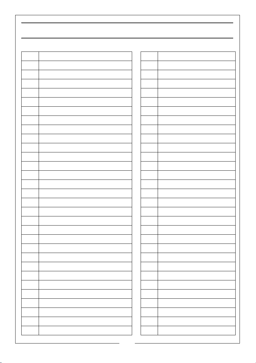
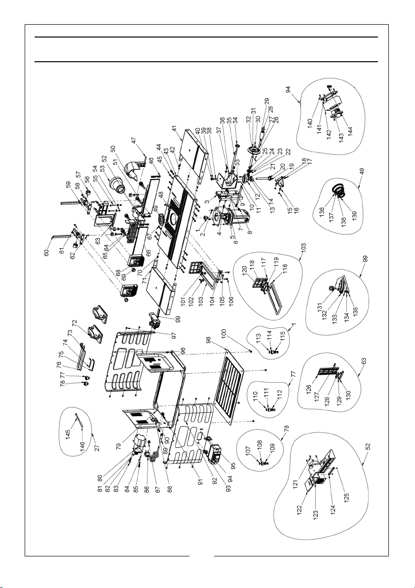
COMPONENT PARTS
No Description No Description
1 Chuck 31 Adjusting handle wheel
2 X-Pan head screw & washer 32 Rise and fall shaft
3 Motor rise & fall guide bar 33 Motor mounting bracket
4 X-Pan head screw 34 Locking knob
5 Motor 35 Locking rod
6 Motor connecting plate 36 Hex socket cap screw
7 Slider 37 Hex socket cap screw
8 Hex socket cap screw 38 Hex socket cap screw
9 Guide profile 39 Spring washer
10 Pointer 40 Flat washer
11 Hex bolt 41 Work table side extension
12 Hex nut 42 Washer
13 Bevel gear support 43 Work table
14 Deep groove ball bearing 44 M5 Locknut
15 Hex nut 45 Hex socket cap screw
16 Hex socket cap screw & washers 46 End cap
17 Hex socket cap screw & washers 47 Straight pin
18 Support assembly 48 Hex socket cap screw
19 Bevel gear 49 Insert ring assembly
20 Vertical adjustment screw 50 Plastic tool cover
21 Circlip 51 Left end cap
22 Flat key 52 Main fence
23 Circlip 53 Dust extract adaptor
24 Vertical adjustment shaft gear 54 M6 Locknut
25 Vertical adjuster 55 Hex bolt M6x40
26 Roll pin 56 Mounting bracket
27 Handle spindle 57 Locking knob
28 Handle cap 58 Square mounting
29 Handle 59 Coachbolt M6x35
30 Dome nut 60 Square support post
26
Parts & Service: 020 8988 7400 / E-mail: [email protected] or [email protected]
Page 27
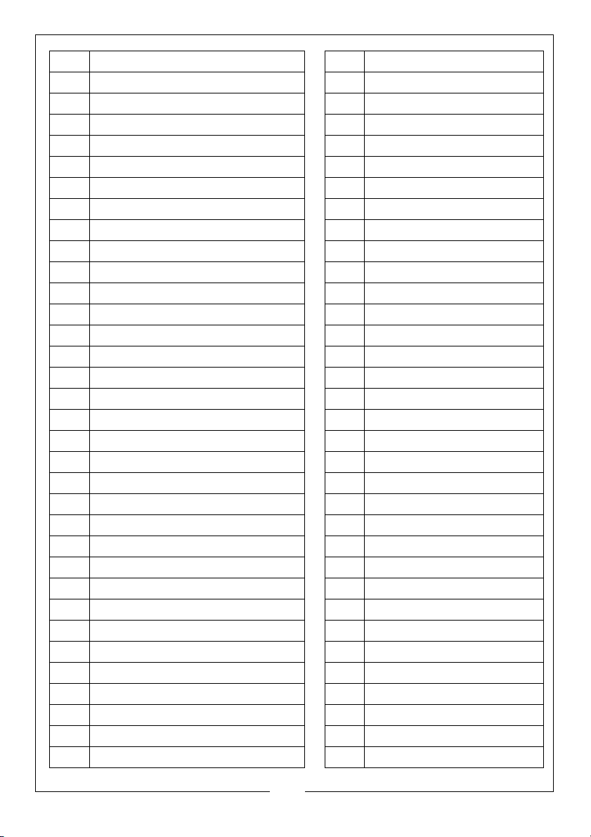
61 T-bar 95 Circuit board
62 Hex socket cap screw M6x16 96 Rear panel
63 Pressure bar 97 X-Pan head screw/washer
64 Sliding cover bracket 98 Base plate
65 Coachbolt M6x20 99 Metre plate assembly
66 Fence Plate 100 X-Pan head screw/washer
67 X-Pan head screw M5x15 101 Butterfly nut
68 Pressure pad 102 Washer A6
69 Lock knob 103 Safety fence assembly
70 Hex socket cap screw M5x12 104 Mounting bracket
71 Worktable side extension 105 X-Pan head screw/washer
72 Push blocks 106 Coachbolt M6x25
73 Long wrench 107 Chuck ring
74 Allen wrench S4 108 Chuck nut
75 Allen wrench S5 109 Collet
76 Short wrench 110 Chuck ring
77 Chuck 12mm 111 Chuck nut
78 Chuck 6mm 112 Collet
79 Base assembly 113 Chuck ring
80 Transformer box 114 Chuck nut
81 Circuit board 115 Collet
82 Hex nut M4 116 Long fence assembly 1
83 X-Pan head screw 117 Long fence assembly
84 X-Pan head s/t screw 118 Pan head screw M5x12
85 Washer 119 Long fence connector
86 Power plug 120 Washer
87 Cable gland 121 Screw M4x12
88 Circlip 122 Fence
89 Power cable gland 123 Grille
90 X-Pan head screw/washer 124 Dowel
91 Cable clamp 125 S/t screw
92 Front panel 126 Mounting plate
93 Over-current protection 127 Countersunk screw
94 On/off switch 128 S/t screw
27
Parts & Service: 020 8988 7400 / E-mail: [email protected] or [email protected]
Page 28

129 Plate connecting bracket 138 Table top cover plate B
130 Connecting bar 139 Table top cover plate A
131 Securing knob 140 Self tapping screw
132 Mitre base with scale 141 Switch box cover
133 Screw 142 Connecting box
134 Washer 143 Switch
135 Slide arm 144 Sheath
136 Table top cover plate C 145 X-Pan head screw
137 Table top cover plate D 146 Handle bush
28
Parts & Service: 020 8988 7400 / E-mail: [email protected] or [email protected]
Page 29

ENVIRONMENTAL PROTECTION
Through purchase of this tool, the customer is taking on the obligation
to deal with the WEEE in accordance with the WEEE regulations in
relation to the treatment, recycling & recovery and environmentally
sound disposal of the WEEE.
In effect, this means that this tool must not be discarded with general waste.
Refer to the laws governing Waste Electrical and Electronic Equipment (WEEE)
at a recognised disposal facility.
GUARANTEE
The machine is guaranteed against faulty manufacture for a period of 12
months from the date of purchase. Your receipt is required as proof of
purchase.
This guarantee is invalid if the machine is found to have been abused,
tampered with, or not used for the purpose for which it was intended.
Faulty goods must be returned to their place of purchase, it must not be
returned to us without prior permission.
This guarantee does not effect your statutory rights.
29
Parts & Service: 020 8988 7400 / E-mail: [email protected] or [email protected]
Page 30

DECLARATION OF CONFORMITY - UK
30
Parts & Service: 020 8988 7400 / E-mail: [email protected] or [email protected]
Page 31
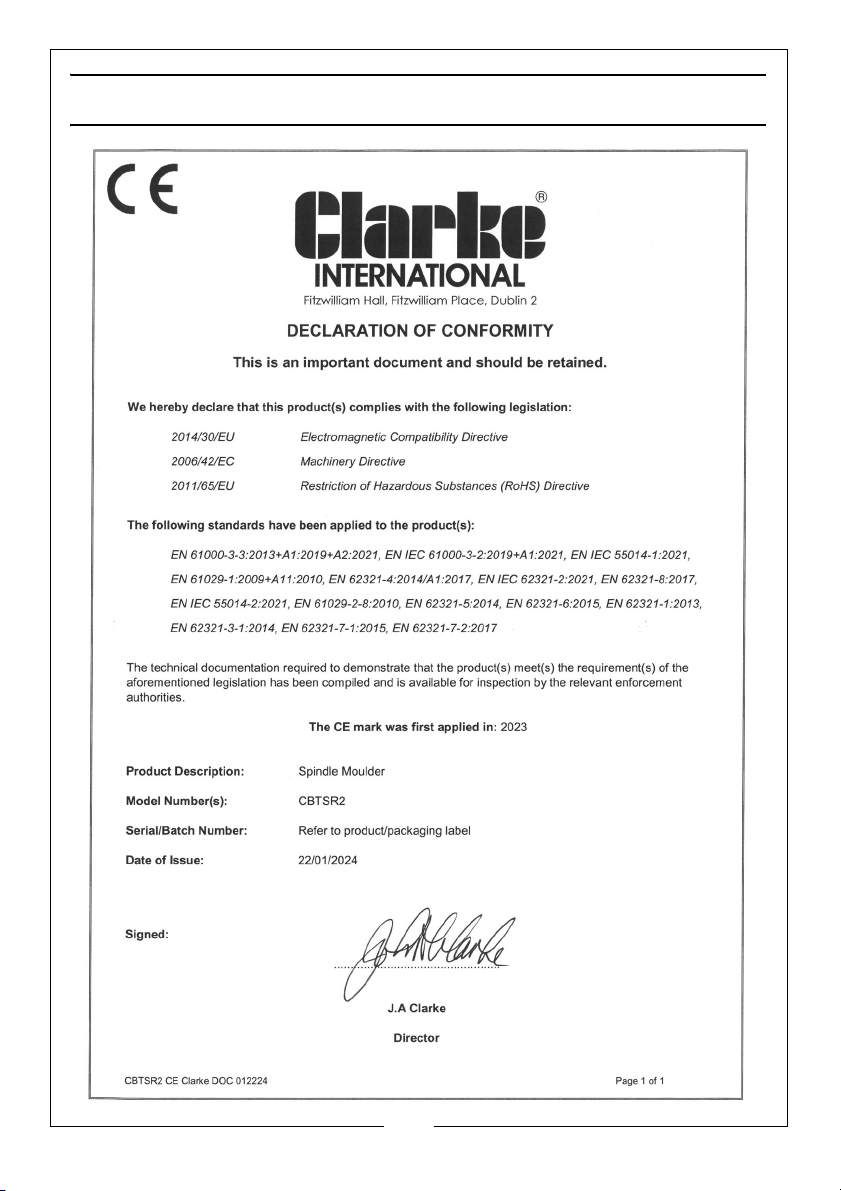
DECLARATION OF CONFORMITY - CE
31
Parts & Service: 020 8988 7400 / E-mail: [email protected] or [email protected]
Page 32

 Loading...