

Page 1
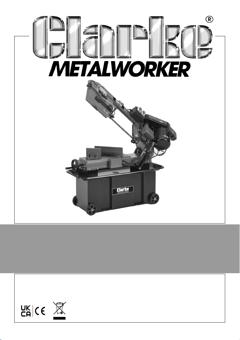
7” METAL CUTTING BANDSAW
MODEL NO: CBS7MC
PART NO: 6460123
OPERATION & MAINTENANCE
INSTRUCTIONS
ORIGINAL INSTRUCTIONS
GC0922 Rev 1
Page 2

INTRODUCTION
Thank you for purchasing this CLARKE Bandsaw which is designed for DIY &
light industrial use.
Before attempting to operate the machine it is essential that you read this
manual thoroughly and carefully follow all instructions given. In doing so you
will ensure the safety of yourself and that of others around you and you can
look forward to the product giving you long and satisfactory service.
GUARANTEE
This CLARKE product is guaranteed against faulty manufacture for a period of
12 months from the date of purchase. Please keep your receipt as proof of
purchase.
This guarantee is invalid if the product is found to have been abused or
tampered with in any way, or not used for the purpose for which it was
intended.
Faulty goods should be returned to their place of purchase, no product can
be returned to us without prior permission.
This guarantee does not effect your statutory rights.
ENVIRONMENTAL PROTECTION
Recycle unwanted materials instead of disposing of them as waste. All
unwanted accessories and packaging should be sorted and taken to a
recycling centre for disposal in a manner which is compatible with the
environment.
ENVIRONMENTAL RECYCLING POLICY
Through purchase of this product, the customer is taking on the
obligation to deal with the WEEE in accordance with the WEEE
regulations in relation to the treatment, recycling & recovery and
environmentally sound disposal of the WEEE.
In effect, this means that this product must not be disposed of with general
household waste but according to the laws governing Waste Electrical and
Electronic Equipment (WEEE) at a recognised disposal facility.
2
Parts & Service: 020 8988 7400 / E-mail: [email protected] or [email protected]
Page 3
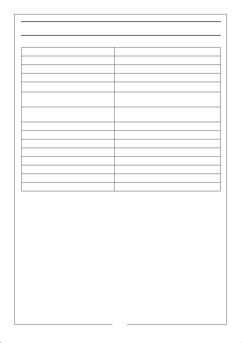
SPECIFICATIONS
Weight 135kg
Dimensions Folded Down (L x W x H) 1220 x 495 x 1001mm
Dimensions Folded Up (L x W x H) 1220 x 495 x 1630mm
Table Height from Floor 610mm
Tilt Angle
Maximum Cutting Capacity@0
Maximum Cutting Capacity@45
o
o
Throat/Cutting Width 335mm
Blade Speed (4 speeds) 22, 33, 45, 65m/min
Blade Size 2360 x 19 x 0.9mm - 6 tpi
Supply Cable Length 1900mm
Sound Power Level Measured (Lw) 85.8dB(A) whilst cutting
Operating Voltage 230V - 50Hz
Output Wattage 1100W
IP Rating IP20
o
0 - 45
Height: 180mm
Width: 270mm
Height: 180mm
Width: 120mm
3
Parts & Service: 020 8988 7400 / E-mail: [email protected] or [email protected]
Page 4
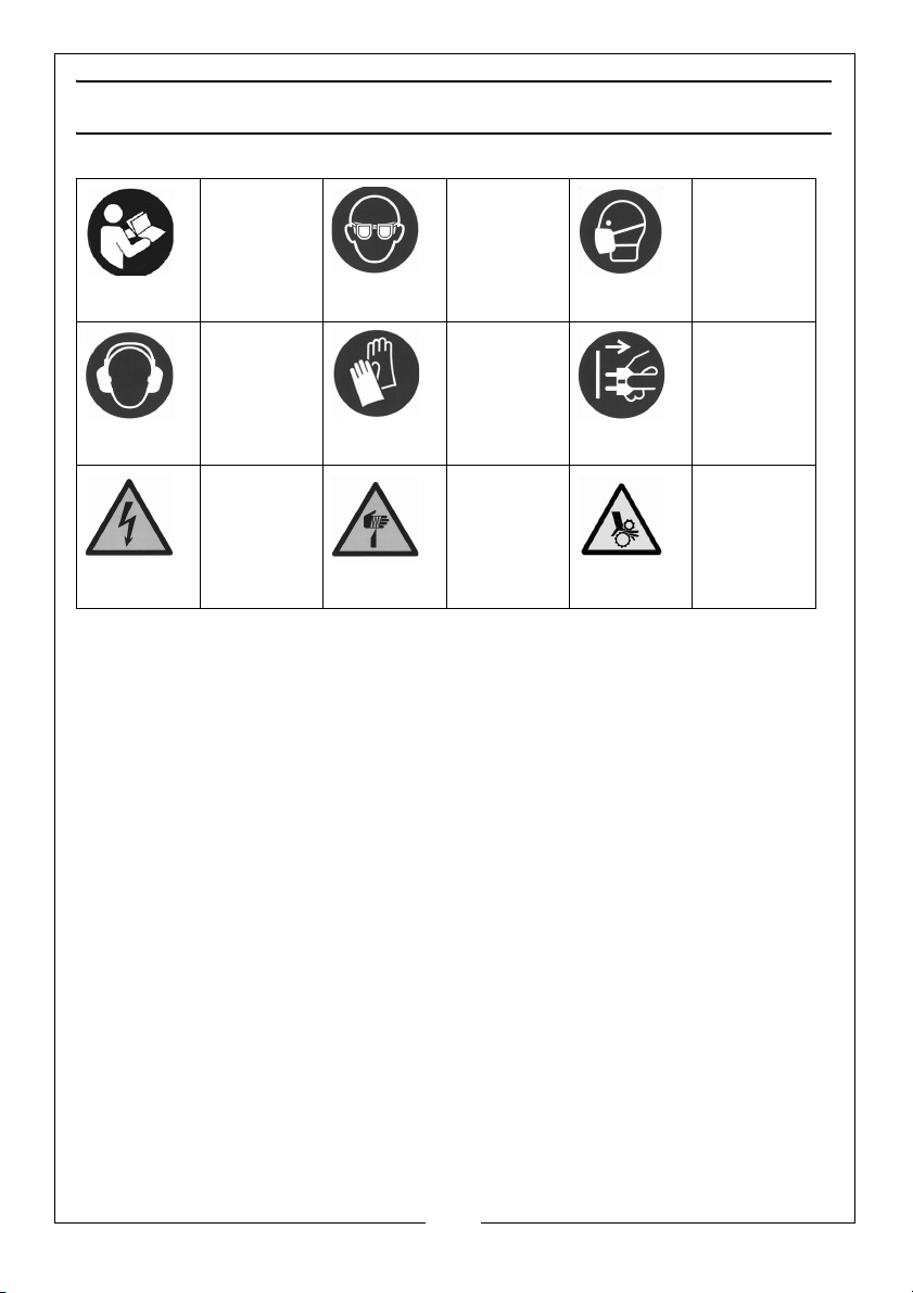
SAFETY SYMBOLS
Read the
manual
and safety
instructions
before use
Wear ear
protection
War ning:
Electricity
Wear eye
protection
Wear
protective
gloves
Warning:
Sharp
Blade
Wear
protective
mask
Disconnect
from Power
Supply
When Not
in Use
Warning:
Risk of
Trapping
Hand/
Fingers
4
Parts & Service: 020 8988 7400 / E-mail: [email protected] or [email protected]
Page 5

SAFETY WARNINGS
CAUTION: FAILURE TO FOLLOW THESE PRECAUTIONS COULD RESULT IN
PERSONAL INJURY, AND/OR DAMAGE TO PROPERTY.
WORK ENVIRONMENT
1. Please read these instructions carefully and retain for future reference.
2. A LWAYS keep the work area clean and well lit. Cluttered and dark areas
invite accidents.
3. DO NOT operate power tools in explosive atmospheres, such as in the
presence of flammable liquids, gases or dust. Power tools create sparks
which may ignite the dust or fumes.
4. This machine is designed for indoor environments only and must not be
used for other purposes.
5. A LWAYS keep children and bystanders away while operating a power tool.
Anyone entering the work area must wear personal protective equipment
(PPE). Distractions can cause you to lose control and fragments of work or
a broken blade may fly away and cause injury.
6. A LWAYS store power tools correctly when not in use. Abrasive products
should be stored in a dry, secure place out of the reach of children.
ELECTRICAL SAFETY
1. Power tool plugs must match the outlet. NEVER modify the plug in any way.
DO NOT use adapter plugs with earthed (grounded) power tools.
Unmodified plugs and matching outlets will reduce the risk of electric
shock.
2. DO NOT expose power tools to rain or wet conditions. Water entering a
power tool will increase the risk of electric shock.
3. DO NOT abuse the power cable. NEVER use the cable for carrying, pulling
or unplugging the power tool. Keep the cable away from heat, oil, sharp
edges or moving parts. Damaged or entangled cables increase the risk of
electric shock.
4. A LWAYS position the power cable so that it cannot be inadvertently pulled
or pinched, and where it does not cause a trip hazard.
5. DO NOT use extension power cables.
6. Before cleaning or maintenance tasks, A LWAY S unplug the machine from
the power supply.
5
Parts & Service: 020 8988 7400 / E-mail: [email protected] or [email protected]
Page 6

PERSONAL SAFETY
1. Stay alert, watch what you are doing and use common sense when
operating a power tool. DO NOT use a power tool while you are tired or
under the influence of drugs, alcohol or medication. A moment of
inattention while operating power tools may result in personal injury.
2. ALWAYS use personal protective equipment (PPE). Wear eye protection,
safety equipment such as dust mask, non-slip safety shoes, hearing
protection and a workshop apron capable of stopping small abrasive or
workpiece fragments.
3. AVOID accidental starting. Ensure the switch is in the off position before
plugging in. Plugging in power tools that have the switch in the on position
invites accidents.
4. ALWAYS remove any adjusting key or wrench before turning the power tool
on. A wrench or a key left attached to a moving part of the power tool
may result in personal injury.
5. DO NOT overreach. Keep proper footing and balance at all times. This
enables better control of the power tool in unexpected situations.
6. Keep your hair and clothing away from moving parts. Loose clothes,
jewellery or long hair can be caught in moving parts.
7. AVOID operator fatigue. Stop the power tool at regular intervals for a short
break to rest hands and arms.
8. This machine must only be used by adults. Children SHOULD NOT
allowed to play with this product.
be
POWER TOOL USE AND CARE
1. DO NOT force the machine. Use the correct power tool for your
application. It will do a better and safer job at the rate for which it was
designed.
2. DO NOT use the power tool if the switch does not turn it on or off. Any
power tool that cannot be controlled with the switch is dangerous and
must be repaired.
3. ALWAYS disconnect the power tool from the power supply before making
any adjustments, changing accessories, or storing the tool. These measures
will reduce the risk of the power tool starting accidently.
4. Store power tools out of the reach of children and DO NOT allow persons
unfamiliar with these instructions to operate the power tool. Power tools are
potentially dangerous in the hands of untrained users.
5. Maintain power tools in top condition. Keep tools/ machines clean for the
best and safest performance. Check for misalignment or binding of
moving parts, broken parts, or any condition that may affect the power
6
Parts & Service: 020 8988 7400 / E-mail: [email protected] or [email protected]
Page 7

tool’s operation. If damaged, have the power tool repaired before use.
Many accidents are caused by poorly maintained power tools. If in doubt,
DO NOT use the machine. Consult your local CLARKE dealer.
6. Machine cleanliness. DO NOT allow the ventilation slots in the machine/
motor to become blocked with dust.
7. Regularly clean the power tool’s air vents. The motor fan will draw dust
inside the housing and accumulation of material could cause electrical or
fire hazards.
8. Maintain your tools. Keep all handles and grips dry and clean.
SERVICING
1. When necessary, have your power tools serviced or repaired by a qualified
person using identical replacement parts (see pages 36-41). This will ensure
that the safety of the power tool is maintained.
ADDITIONAL PRECAUTIONS FOR BANDSAWS
1. A LWAYS check safety guards are in place and functioning correctly before
switching the machine on.
2. A LWAYS use the appropriate saw blade for the material being cut.
3. NEVER use the machine if the electric cable, plug or motor is in poor
condition.
4. NEVER touch the blade immediately after use, when changing the blade
always allow time for it to cool.
5. NEVER use bent or cracked blades. (Replacement blades are available
from your CLARKE dealer, see page 32).
6. When cutting round stock, use a suitable jig or fixture to keep the work from
turning.
7. A LWAYS ensure the blade is fully tightened and correctly adjusted before
use.
8. A LWAYS switch the machine off immediately the task is completed.
7
Parts & Service: 020 8988 7400 / E-mail: [email protected] or [email protected]
Page 8
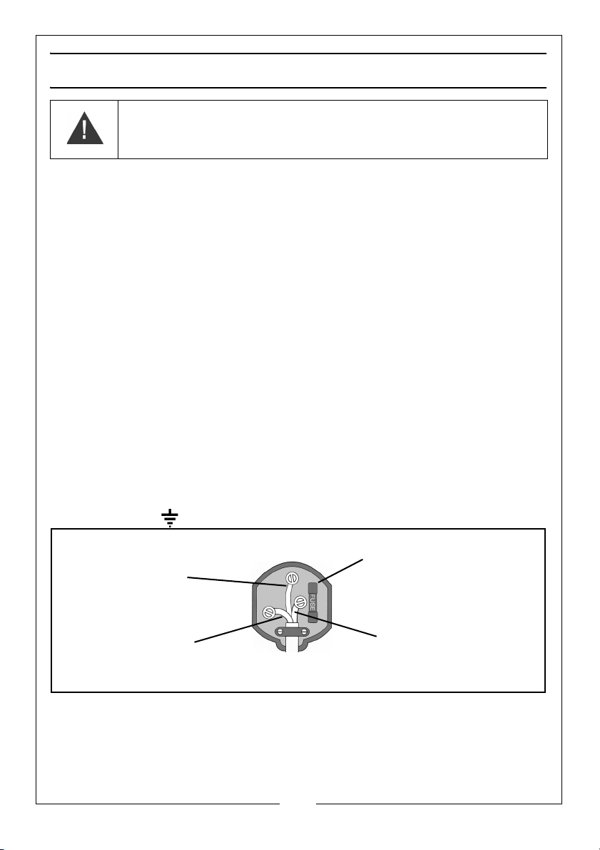
ELECTRICAL CONNECTIONS
Plug must be BS1363/A approved.
Always fit a 13 Amp fuse.
Ensure that the outer sheath of the cable is firmly held by the clamp
Neutral
(Blue)
Live
(Brown)
Earth
(Green and Yellow)
WARNING! Read these electrical safety instructions thoroughly
before connecting the product to the mains supply.
Before switching the product on, make sure that the voltage of your electricity
supply is the same as that indicated on the rating plate. This product is
designed to operate on 230VAC 50Hz. Connecting it to any other power
source may cause damage.
This product may be fitted with a non-rewireable plug. If it is necessary to
change the fuse in the plug, the fuse cover must be refitted. If the fuse cover
becomes lost or damaged, the plug must not be used until a suitable
replacement is obtained.
If the plug has to be changed because it is not suitable for your socket, or due
to damage, it should be cut off and a replacement fitted, following the wiring
instructions shown below. The old plug must be disposed of safely, as insertion
into a mains socket could cause an electrical hazard.
If the colours of the wires in the power cable of this product do not correspond
with the markings on the terminals of your plug, proceed as follows.
•The Blue wire must be connected to the terminal which is marked N or
coloured Black.
•The Brown wire must be connected to the terminal which is marked L or
coloured Red.
•The Yellow and Green wire must be connected to the terminal which is
marked E or or coloured Green.
We strongly recommend that this machine is connected to the mains supply
via a Residual Current Device (RCD)
If in any doubt, consult a qualified electrician. DO NOT attempt any repairs
yourself.
Parts & Service: 020 8988 7400 / E-mail: [email protected] or [email protected]
8
Page 9
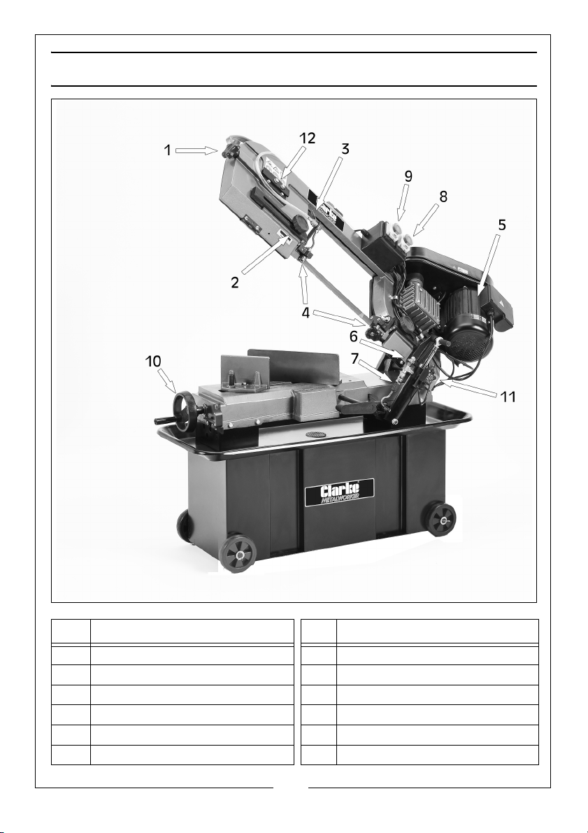
OVERVIEW
Item Description Item Description
1 Blade Tension Handle 7 Feed ON/OFF Valve Lever
2 Blade Guide Adjustment Knob 8 Lubricant Pump ON/OFF Switch
3 Lubricant Control Valve 9 Saw Motor ON/OFF Switch
4 Blade Guides 10 Vice Handwheel
5 Motor 11 Automatic Shut Off Switch
6 Feed Rate Control Knob 12 Blade Tracking Controls
9
Parts & Service: 020 8988 7400 / E-mail: [email protected] or [email protected]
Page 10
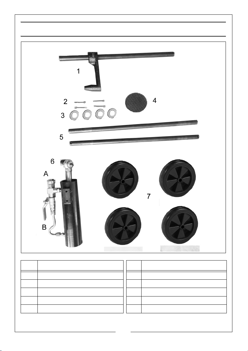
ASSEMBLY PARTS
Item Description Item Description
1 Work Stop and Rod 6 Hydraulic Cylinder
2 4 x 3mm x 30mm Cotter Pin 6A Feed Rate Control Knob
3 4 x 5/8” Washer 6B Feed ON/OFF Valve Lever
4 Swarf Screen 7 4 x Wheel & Covers
5 2 x Wheel Axle
10
Parts & Service: 020 8988 7400 / E-mail: [email protected] or [email protected]
Page 11

ASSEMBLY & SET UP
The bandsaw comes partly assembled. Unpack and lay out all the items and
identify each one, referring to pages 9 & 10.
If any parts are missing, immediately contact the dealer where the product
was purchased.
CLEAN UP
The unpainted surfaces of your machine are coated with a heavy duty rust
preventative that prevents corrosion during shipment and storage. This rust
preventative works extremely well, but it will take a little time to clean.
There are many ways to remove this rust preventative, but the following steps
work well in a wide variety of situations. Always follow the manufacturers
instructions with any cleaning product you use and make sure you work in a
well ventilated area to minimise exposure to toxic fumes.
BEFORE CLEANING, GATHER THE FOLLOWING:
• Disposable rags/cloth
• Cleaner/degreaser
• Safety glasses & disposable gloves
• Plastic paint scraper (optional)
BASIC STEPS FOR REMOVING RUST PREVENTATIVE
1. Coat the rust preventive with a liberal amount of cleaner/degreaser and
let it soak for 5-10 minutes.
2. Wipe off the surface. If the cleaner/degreaser is effective, the rust
preventative will wipe off easily. If you have a plastic paint scraper, scrape
off as much as you can first, then wipe off the rest with a rag.
3. Repeat steps 1 & 2 as necessary until clean, then coat all unpainted
surfaces with a quality metal protectant to prevent rust.
SHIPPING BRACKET
A shipping bracket has been installed on the bandsaw to protect the
alignment of the bow during shipment. After removal, store the bracket in a
safe place until you need to move or ship the bandsaw in the future.
11
Parts & Service: 020 8988 7400 / E-mail: [email protected] or [email protected]
Page 12
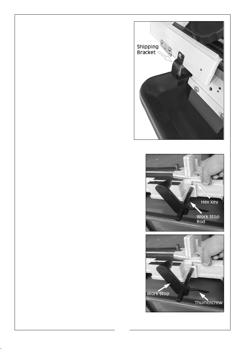
1. Unbolt the shipping bracket shown
here.
NOTE: Retain all components, as the
bracket can be reinstated if the
bandsaw needs transporting/
shipping in the future.
INSTALLING WORK STOP
1. Insert the work stop rod through the hole in
the base and lock in place with a hex key
and screw.
2. Slide work stop over the rod.
3. Measuring from the outside of the blade,
tighten the thumbscrew to set the work
stop at the desired length.
12
Parts & Service: 020 8988 7400 / E-mail: [email protected] or [email protected]
Page 13
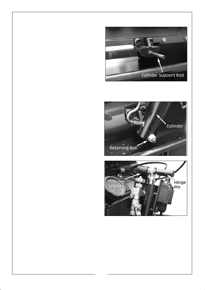
INSTALLING THE HYDRAULIC CYLINDER
1. Unscrew the retaining nut from the
cylinder support rod and tighten
the bolts that hold it to the side of
the machine using a 17mm
spanner.
2. Slide the cylinder onto the rod, as
shown, with the feed rate control
knob pointing upwards and refit
the retaining nut into position at
the end of the support rod.
3. Insert the hinge pin through the
hole in the end of the piston and
move the cylinder upwards
towards the cylinder bracket
attached to the main arm.
NOTE: In order to screw the hinge
pin into the bracket, it may
be necessary to depress the
piston. Alternatively, get a
second person to raise and
support the bandsaw arm
until the hinge pin is aligned with the hole in the bracket.
4. Screw in and tighten the hinge pin using a 14mm spanner.
13
Parts & Service: 020 8988 7400 / E-mail: [email protected] or [email protected]
Page 14
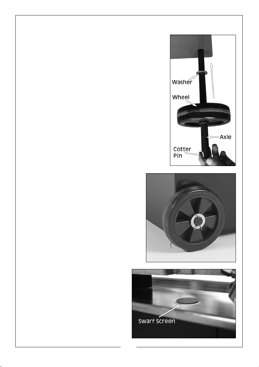
INSTALLING THE WHEELS
COMPONENTS & HARDWARE NEEDED
• 4 x Wheels
• 2 x Axle
• 4 x Cotter Pins (3 x 30mm)
• 4 x Flat Washers (5/8”)
1. Slide axle through the holes in the bottom of the
cabinet.
2. Slide the flat washers onto the axle,
followed by the wheels. Secure the
wheels with the cotter pins as shown.
INSTALLING THE SWARF SCREEN
1. To prevent swarf getting into the
blade lubricant and pump, place
the swarf screen over the
drainage hole in the centre of the
drip tray as shown.
14
Parts & Service: 020 8988 7400 / E-mail: [email protected] or [email protected]
Page 15
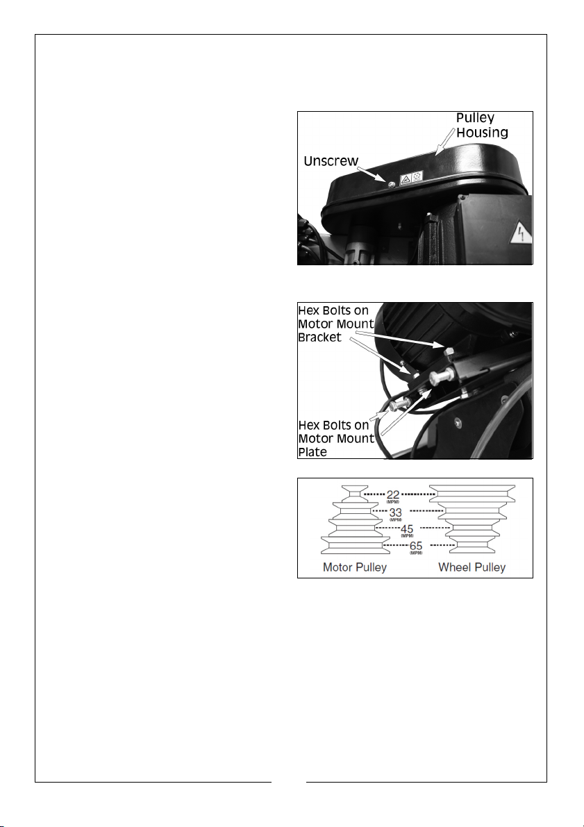
DRIVE V-BELT
The drive belt may need to be tensioned or repositioned for your desired
speed.
1. Disconnect the machine from the
power supply.
2. Unscrew the cover to the pulley
housing
3. Loosen the two hex bolts on the
motor mount bracket, as shown.
4. Adjust the two hex bolts on the
motor mount plate to loosen the
belt.
5. Slip the belt over the combination
of pulleys to get the desired
meters per minute, MPM (see
adjacent chart). Make sure the
belt is on parallel pulley wheels.
6. Readjust and tighten the two hex
bolts on the motor mount plate.
7. Retighten the two hex bolts on the motor mount bracket.
CUTTING SPEED RATE RECOMMENDATION
Selecting the right blade speed for cutting depends on the type of material
being cut. Selecting the correct blade speed prolongs the life of the blade
and provides the best possible cutting results.
15
Parts & Service: 020 8988 7400 / E-mail: [email protected] or [email protected]
Page 16

The Cutting Speed Rate Recommendation Chart that follows offers guidelines
only for various metals, given in feet per minute (FPM) and meters per minute
(MPM). Choose the speed closet to the number shown in the chart.
Material Speed FPM (MPM) Material Speed FPM (MPM)
Carbon Steel 196 - 354
(60 - 108)
Tool Steel 203
(62)
Alloy Steel 111 - 321
(34 - 98)
Free Machining
Stainless Steel
150 - 203
(46 - 62)
Angle Steel 180 - 220
(54 - 67)
High Speed Tool
Steel
75 - 118
(25 - 36)
Mold Steel 246
(75)
Cold Work Tool
Steel
Hot Work Tool
Steel
Water Hardened
Tool Steel
95 - 213
(29 - 65)
203
(62)
246
(75)
Oil Hardened Tool
Steel
206 - 2132
(62 - 65)
Stainless Steel 85
(26)
CR Stainless Steel 85 - 203
(26 - 62)
Thin Tube 180 - 220
(54 - 67)
Aluminum Alloy 220 - 534
(67 - 163)
Copper Alloy 229 - 482
(70 - 147)
Grey Cast Iron 108 - 225
(33 - 75)
Ductile Austenitic
Cast Iron
Malleable Cast
Iron
65 - 85
(20 - 26)
321
(98)
Plastic 220
(67)
BLADE SELECTION
TOOTH PITCH
Usually measured as TPI (teeth per inch), tooth pitch determines the size/
number of the teeth. More teeth per inch (fine pitch) will cut slower but
smoother, while fewer teeth per inch (coarse pitch) will cut rougher but faster.
As a general rule, choose blades that will have at least three teeth in the
material at all times. Use fine pitched blades on harder metals and coarse
pitched blades on softer metals. When selecting blades blades, refer to the
above chart and following diagram for recommended blade tooth (TPI) and
speed (FPM) based on workpiece material.
16
Parts & Service: 020 8988 7400 / E-mail: [email protected] or [email protected]
Page 17
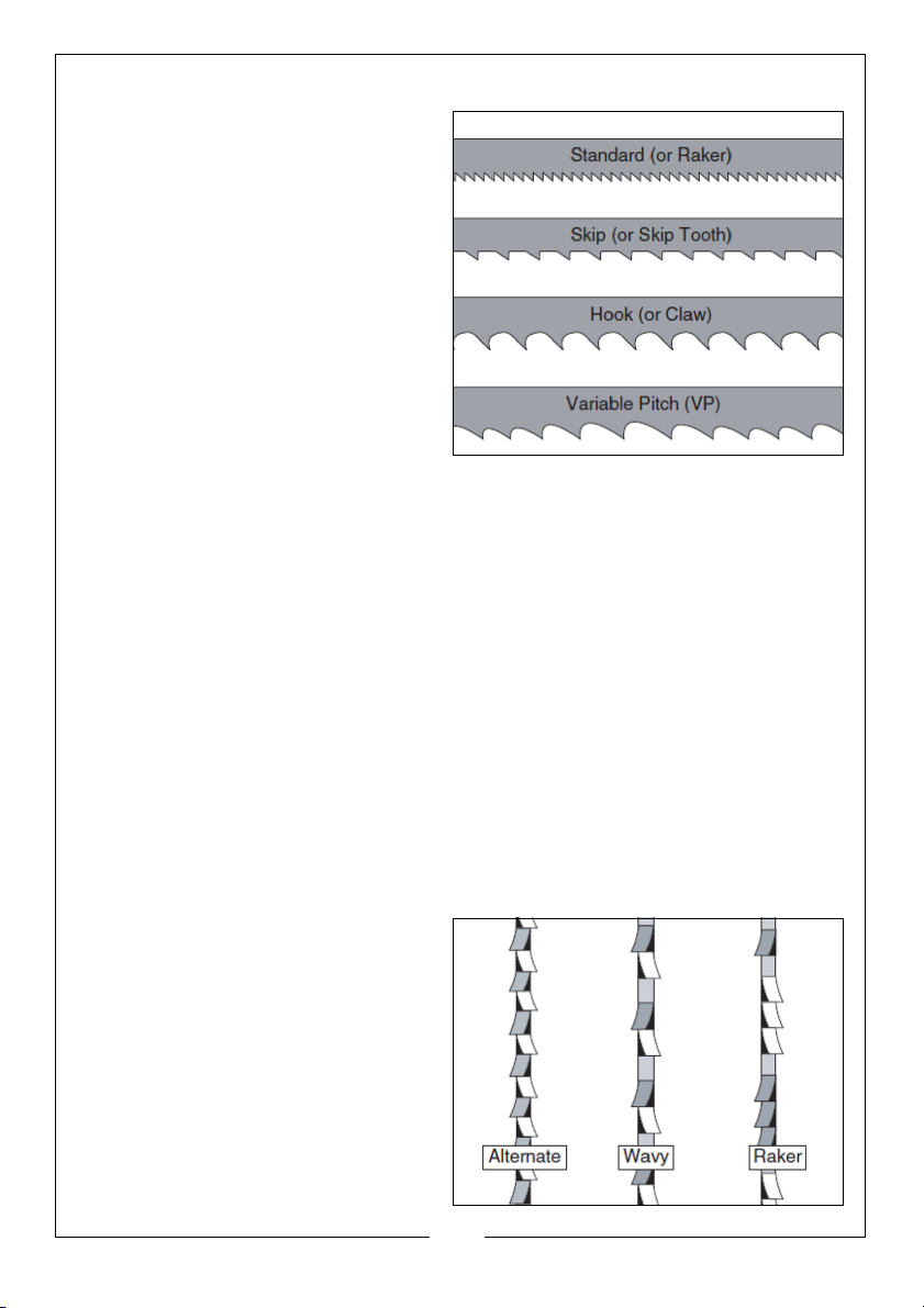
TOOTH STYLE
When selecting blades, another
option to consider is the shape,
gullet size, teeth set and teeth
angle, otherwise known as Tooth
Style. Many blade manufacturers
offer variations of the four basic
styles, as shown.
• Standard: This style is considered to be the standard because the tooth size
and shape are the same as the tooth gullet. The teeth on these blades
usually are very numerous, have no angle and produce cuts by scraping
the material; these characteristics result in very smooth cuts, but do not cut
fast and generate more heat that other types while cutting.
• Skip: This style is similar to a raker blade that is missing every other tooth.
Because of the design, skip toothed blades have a much larger gullet than
raker blades, and therefore cuts faster and generate less heat. However,
these blades also leave a rougher cut than the raker blades.
• Hook: The teeth on this style have a positive angle (downward) which
makes them dig into the material and the gullets are usually rounded for
easier waste removal. These blades are excellent for the tough demands
of re-sawing and ripping thick material.
• Variable Pitch: These blades typically feature combinations of tooth styles
that provide qualities of both.
TOOTH SET
Three of the most common tooth
sets are Alternate, Wavy & Raker
17
Parts & Service: 020 8988 7400 / E-mail: [email protected] or [email protected]
Page 18
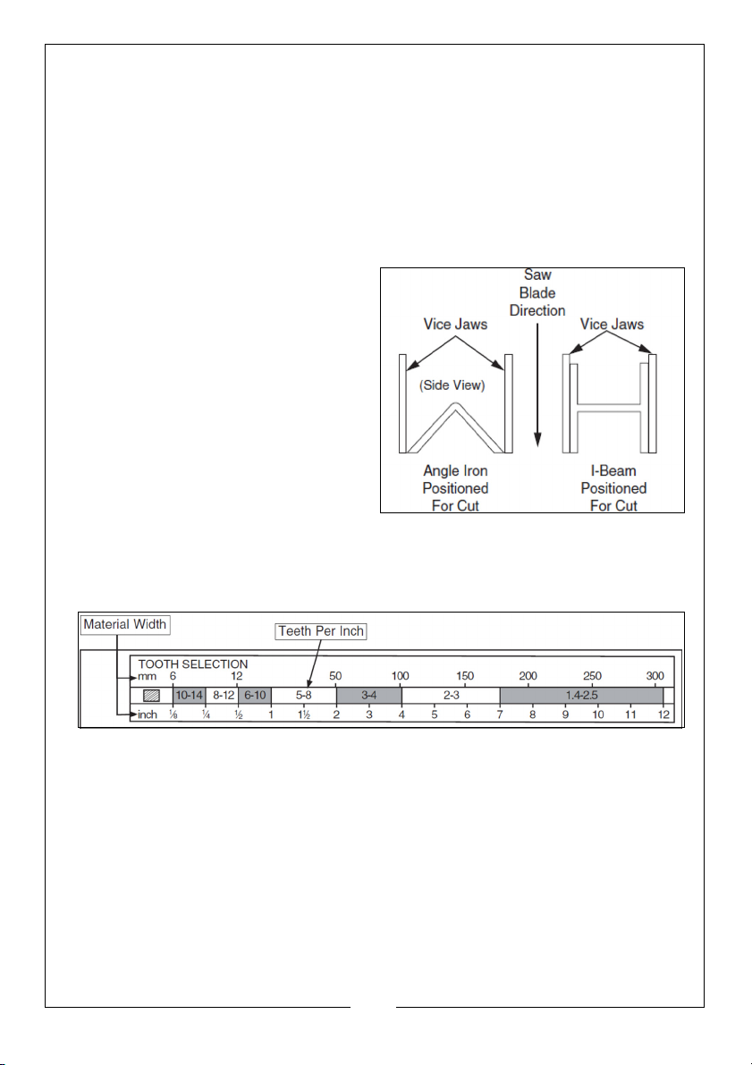
CHOOSING BLADE TPI
Selecting the right blade for the job depends on a variety of factors, such as
type, hardness and shape of the material being cut, machine capability and
operator technique.
The chart below is a basic starting point for choosing blade type based on
teeth per inch (TPI) for variable tooth pitch blades and for standard raker type
bi-metal blades/HSS blades. As a general rule, there should be at least 3 teeth
in contact with the workpiece at all times. However, for exact specifications of
bandsaw blades, contact the blade manufacturer.
When cutting structural shapes such
as angle iron or I-beams, workpieces
should be positioned to maintain the
same material width throughout the
cut, as illustrated.
To select the correct blade TPI:
1. Measure the material thickness.
This measurement is the length of
cut taken from where the tooth
enters the workpiece, sweeps
through and exits the workpiece.
2. Refer to the Material Width row of
the blade selection chart below and read across to find the workpiece
thickness you need to cut.
3. In the centre row, find the TPI that corresponds to the workpiece thickness.
TEST RUN
Once the assembly has been completed, test run the machine to ensure it is
properly connected to the power and safety components are functioning
correctly.
If you find an unusual problem during the test run, immediately stop the
machine, disconnect it from the power source and fix the problem before
operating the machine again. The troubleshooting table on page 33-35 of this
manual may help.
18
Parts & Service: 020 8988 7400 / E-mail: [email protected] or [email protected]
Page 19
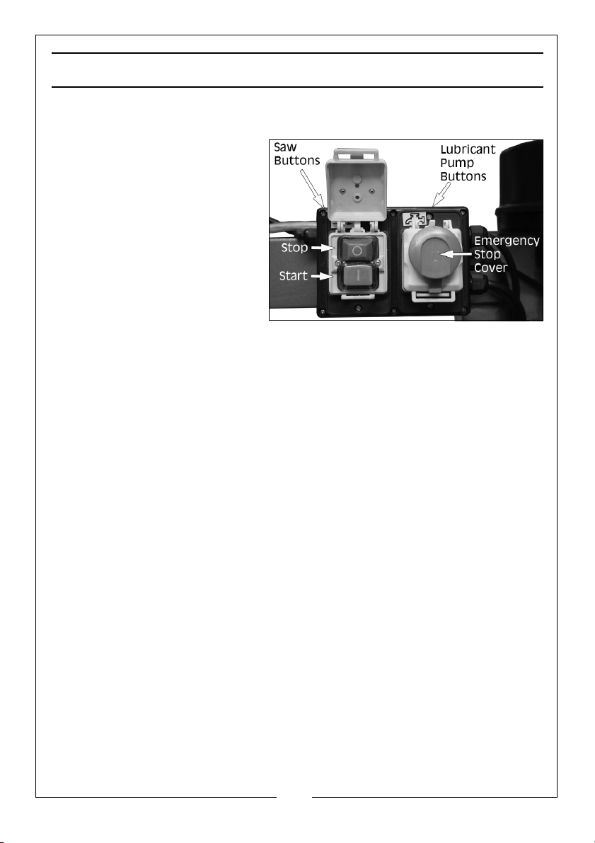
OPERATION
STARTING & STOPPING
The bandsaw has two start/stop
buttons. One for the saw motor
and one for the lubricant pump.
They both have a spring loaded
emergency stop cover, which
should always be in the down
position when the bandsaw is in
operation.
OPERATING TIPS
The following tips will help you safely and effectively operate your bandsaw
and help you get the maximum life out of your saw.
Tips for horizontal cutting:
• Use work stop to quickly and accurately cut multiple pieces of stock to the
same length.
• Clamp material firmly in the vice jaws to ensure a straight cut through the
material.
• Let the blade reach full speed before engaging with the workpiece. Never
start a cut with the blade in contact with the workpiece.
• Wait until the blade has completely stopped before removing workpiece
from the vice, and avoid touching the cut end as it could be very hot.
• Support long workpieces so they won't fall when cut and flag ends of
workpieces to alert passers-by of potential danger.
• Use coolant when possible to increase blade life.
• Loosen blade tension at the end of each day to prolong blade life.
WORK VICE
The vice can cut angles from 0o - 45o and hold material up to 10.5” wide at 0o
to 5” wide at 45
Parts & Service: 020 8988 7400 / E-mail: [email protected] or [email protected]
o
.
19
Page 20
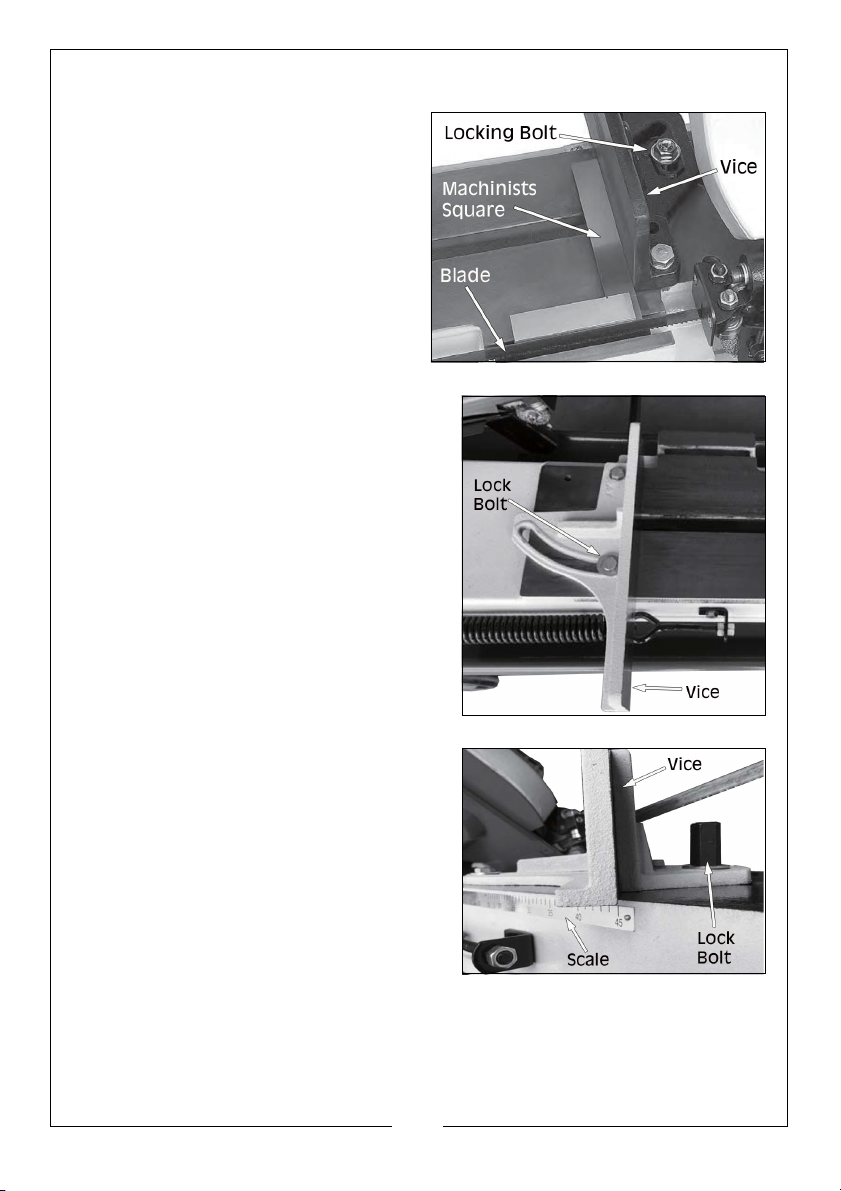
TO SQUARE VICE TO BLADE
1. Loosen the locking bolt, as shown.
2. Use the scale as a guide to set
your angle, or a machinists square
to square the blade to the vice.
3. Tighten the lock bolt.
TO ADJUST VICE ANGLE
1. Loosen the lock bolt on the rear jaw,
as shown, with a wrench.
2. Use the scale to set your angle.
3. Tighten the lock bolt.
4. Loosen the lock bolt on the opposite
jaw, as shown, so the jaw can float,
and match the angle of the
workpiece.
5. Tighten vice against the workpiece.
6. Tighten the lock bolt.
20
Parts & Service: 020 8988 7400 / E-mail: [email protected] or [email protected]
Page 21
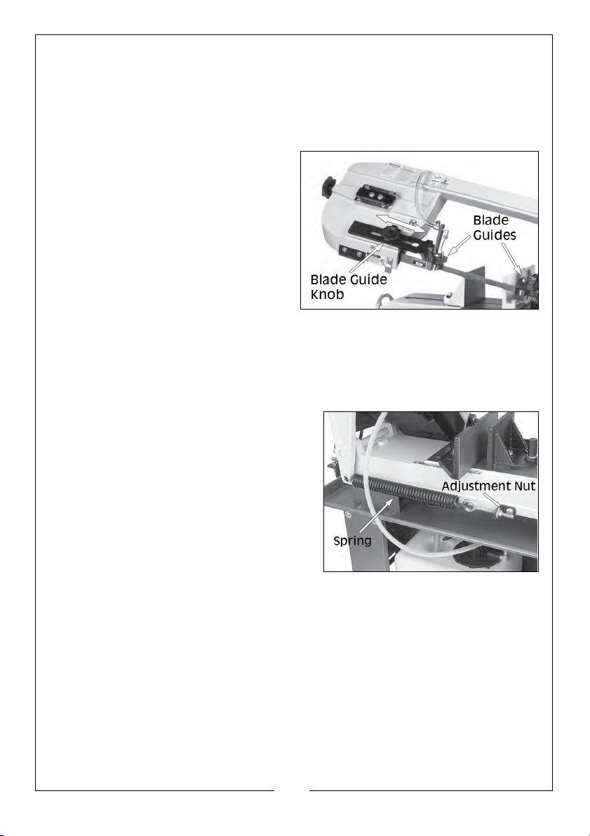
BLADE GUIDES
The blade guides should be positioned approximately 1/4” away from the
workpiece if possible. This will help ensure straight cuts by keeping the blade
from twisting and drifting off the cut line.
To adjust the blade guides:
1. Loosen the blade guide knob as
shown.
2. Slide the blade guide as close to
the workpiece as possible.
3. Tighten blade guide knob.
FEED RATE
The speed at which the saw blade will cut through a workpiece is controlled
by blade type, feed rate and feed pressure.
To set feed rate:
1. Raise the bow to maximum height to
remove spring tension. Close the ON/
OFF valve on the hydraulic cylinder to
lock bow in place.
2. Adjust feed pressure tension spring by rotating the adjustment nut, as
shown. Tighten enough to remove play but not enough to apply tension to
spring.
NOTE: This spring adjustment is an initial setting. Depending on cutting
circumstances, you will have to fine tune the feed pressure with
this adjustment. Increasing the spring tension will reduce the feed
pressure.
21
Parts & Service: 020 8988 7400 / E-mail: [email protected] or [email protected]
Page 22
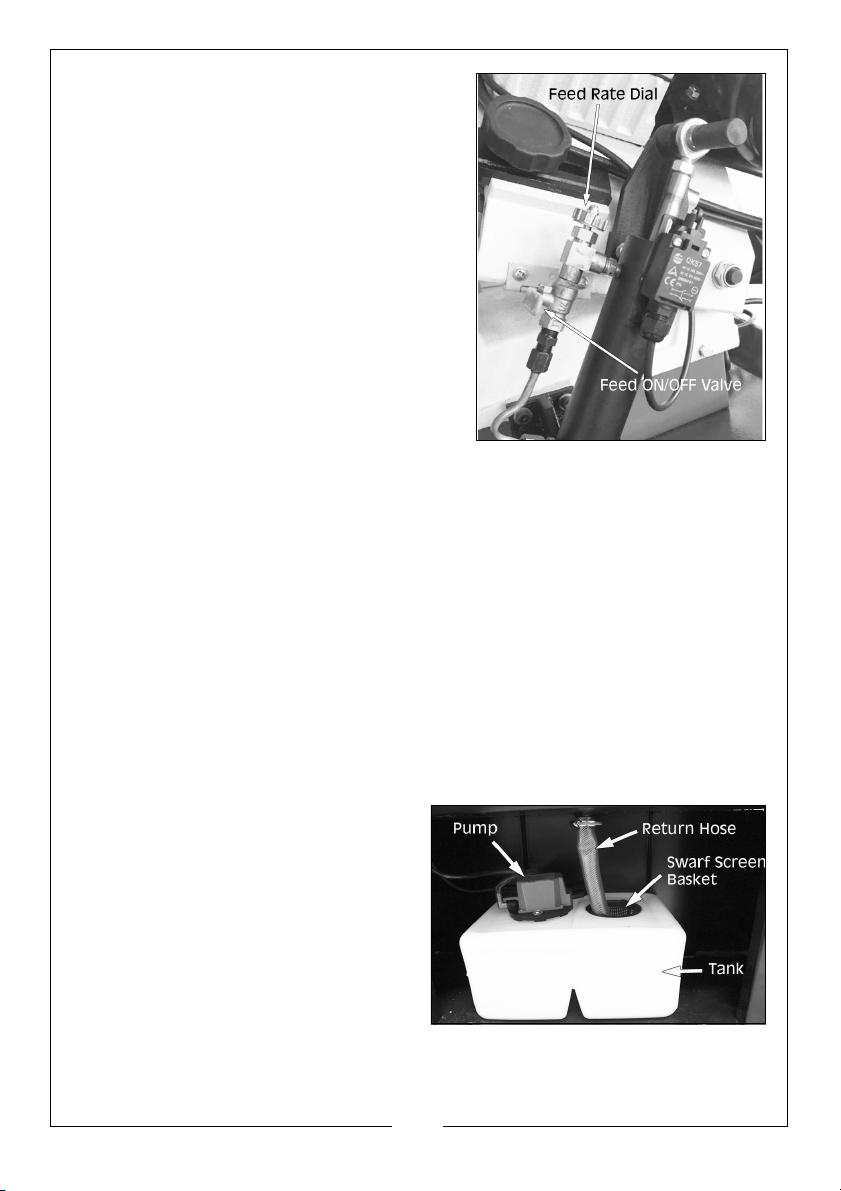
3. Clamp workpiece in table vice.
4. Close the feed ON/OFF valve to lock
the bow and blade a few inches above
the workpiece.
5. With the correct saw blade and blade
speed selected, turn the saw and
lubricant pump ON.
6. Open the ON/OFF valve, then slowly
rotate the feed rate dial clockwise to a
slow feed rate until the saw begins to
cut the workpiece.
7. Observe the chips that exit the cut, and
increase or decrease the feed rate
according to the following chip
characteristics.
• If the chips are tightly curled, warm shavings, brown to black colour, there is
too much downward pressure.
• If the chips are blue looking chips, the blade speed is too high.
• If the chips are thin and powder like, there is insufficient feed pressure. This
will dull your blade rapidly.
BLADE LUBRICATION
To increase cutting efficiency and to prolong the blade life, it is recommended
that a water soluble cutting lubricant is used with this bandsaw. The 16 litre
lubricant tank is located in the base unit of the bandsaw and can be
accessed via the rear of the base unit. To fill the tank and use, proceed as
follows:
ADDING CUTTING LUBRICANT
1. Always disconnect the machine
from the power source before
adding or changing the lubricant.
2. Slide the tank out of the base unit
and unscrew the pump.
NOTE: Due to the power cable to
the pump, the pump must
stay with the bandsaw.
3. Fill the tank with a suitable
lubricant fluid (16 litre capacity)
(see page 32)
22
Parts & Service: 020 8988 7400 / E-mail: [email protected] or [email protected]
Page 23
4. Replace the pump and slide the tank back into the base unit.
5. Replace the return hose back into the hole with the swarf screen basket.
USING THE CUTTING LUBRICANT
1. Check that there is sufficient lubricant in the tank and the pump inlet is
submerged.
1. Adjust and set the bandsaw up to
cut the required item.
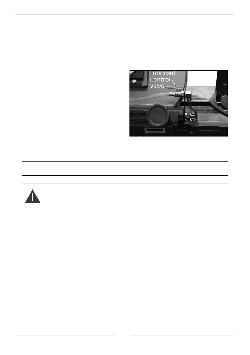
2. Turn the lubricant pump on and
adjust the lubricant control valve
to the desired feed rate.
3. Turn on the bandsaw and
commence cutting.
NOTE: When the bandsaw is not in
use for long periods or needs
transporting, it is
recommended that you empty the lubricant tank.
MAINTENANCE
WARNING: ALWAYS SWITCH OFF AND DISCONNECT FROM THE POWER
SUPPLY BEFORE CARRYING OUT ANY CLEANING OR MAINTENANCE
TASKS.
GENERAL
Remove all accumulated swarf from inside the bandsaw frequently using a
soft brush and/or vacuum cleaner. Alternatively, if compressed air is used,
ensure it is set to no more than 10 psi and wear protective safety glasses.
Maintain a thin film of oil on all unpainted surfaces including all screw threads
to protect your saw from corrosion.
For optimum performance from your machine, follow this maintenance
schedule and refer to any specific instructions given in this section.
DAILY CHECK:
• Loose mounting bolts
• Damage to saw blade
• Worn or damaged wires
• Any other unsafe condition
23
Parts & Service: 020 8988 7400 / E-mail: [email protected] or [email protected]
Page 24
• Clean after each use
• Check blade tension
MONTHLY CHECK:
• Lubricate vice screw (see below)
• Check gear box lubrication (see page 25)
CLEANING
Cleaning the machine is relatively easy. Vacuum clean excess metal chips
and sawdust, and wipe off the remaining dust with a dry cloth. If any resin has
built up, use a resin dissolving cleaner to remove it. Treat all unpainted cast
iron and steel with a non-staining lubricant after cleaning.
LUBRICATION
An essential part of lubrication is cleaning the components before lubricating
them. This step is critical because grime and chips build up on lubricated
components over time, which makes them hard to move.
Clean all exterior components in this section with mineral spirits, shop rags and
brushes before lubricating.
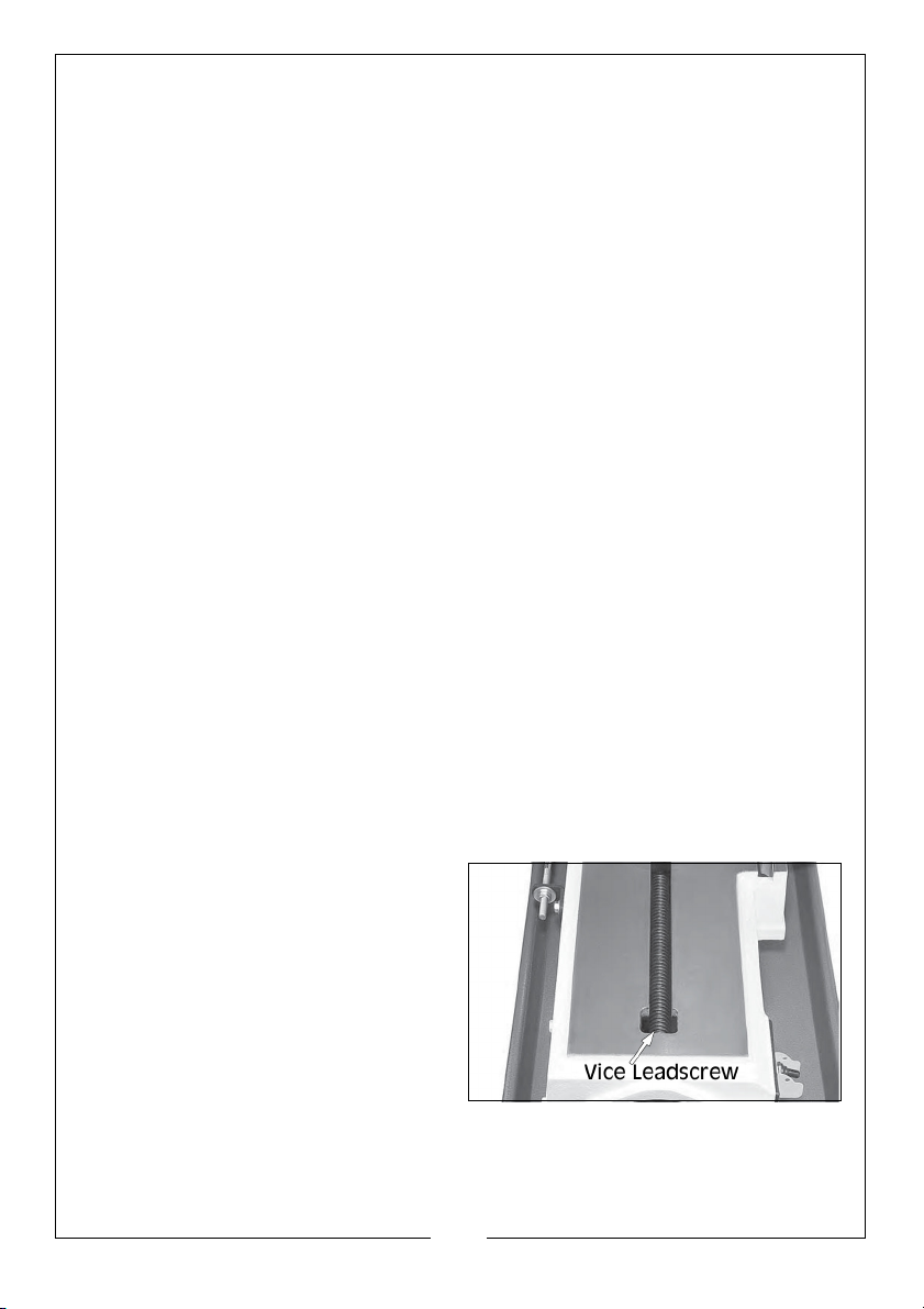
VICE LEADSCREW
• Lube Type: ISO 68 equivalent oil
•Lube Amount: Thin Coat
• Lube Frequency: Every 40 Hours of operation
TO LUBRICATE VICE LEADSCREW
1. Disconnect the machine from the power supply.
2. Using the vice hand wheel, move the vice as far froward as possible.
3. Use mineral spirits and a brush to
clean existing grease and debris
off of the vice leadscrew, and
allow to dry.
4. Apply thin coat of machine oil to
exposed leadscrew threads, then
move the vice through its full
range of motion several times to
disperse the oil along the full
length of the leadscrew.
24
Parts & Service: 020 8988 7400 / E-mail: [email protected] or [email protected]
Page 25
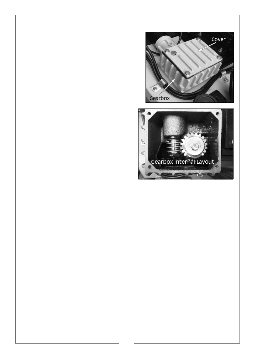
GEARS
• Lube Type: NLGI#2 equivalent grease
• Lube Amount: Thin coat
• Lube Frequency: Every 90 Hours of
operation
TO LUBRICATE GEARS
1. Disconnect the machine from the
power supply.
2. Remove the cover from the gearbox.
3. Using a small brush, apply a thin coat
of grease to the headstock gears.
4. Re-install the gearbox cover
removed in step 2.
5. Operate the saw to work the grease
through the gears.
BLADE CHANGE
The blade should be changed when it becomes dull, damaged or when you
are using materials that require a blade of a certain type or tooth count (see
page 31 for replacement blades).
TO CHANGE THE BLADE
1. Disconnect the machine from the power source.
25
Parts & Service: 020 8988 7400 / E-mail: [email protected] or [email protected]
Page 26
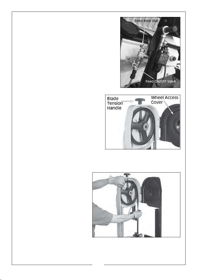
2. Raise the bow of the bandsaw to the
vertical position, close the feed ON/OFF
valve to lock the bow in place and open
the wheel access cover.
3. Remove the blade guards.
4. Turning anti-clockwise, loosen the
blade tension handle, as shown, and
slip the blade off the wheels.
5. Install new blade around the bottom wheel and through both blade guide
bearings.
6. With the blade around the
bottom wheel, slip it around
the top wheel as shown,
keeping the blade between
the blade guide bearings
26
Parts & Service: 020 8988 7400 / E-mail: [email protected] or [email protected]
Page 27
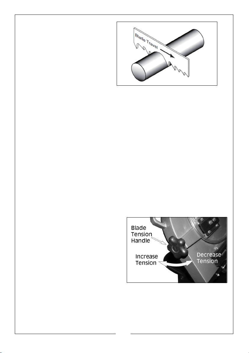
NOTE: It is possible to flip the
blade inside out, in
which case the blade
will be installed in the
wrong direction. Check
to make sure the blade
teeth are facing towards
the workpiece, as
shown. Some blades
have a directional arrow
as a guide.
7. When the blade is around both wheels, adjust so the back of the blade is
against the shoulder of the wheels.
8. Complete blade change by following the steps in the Blade Tension &
Tracking on page 26.
BLADE TENSION & TRACKING
NOTE: Loosen blade tension at the end of each day to prolong blade life.
Correct blade tension is essential to long blade life, straight cuts and efficient
cutting. This machine features a blade tension indicator to assist you with
blade tensioning.
Two major signs that you do not have correct blade tension are:
1. The blade stalls in the cut and slips on the wheels.
2. The blade frequently breaks from being too tight.
TO TENSION BLADE ON BANDSAW
1. Turn the blade tension handle
clockwise to increase tension to
the blade, anti-clockwise to
release tension to the blade.
27
Parts & Service: 020 8988 7400 / E-mail: [email protected] or [email protected]
Page 28
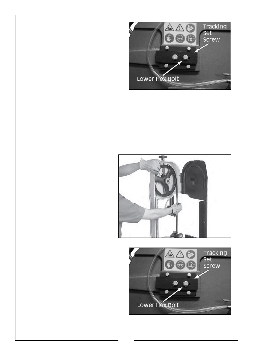
2. Using the blade tension controls,
as shown, tension the blade to the
required amount.
3. To fine tune the blade tension, use a blade tensioning gauge.
TO ADJUST BLADE TRACKING ON BANDSAW
The blade tracking has been correctly set at the factory. The tracking will
rarely need to be adjusted if the bandsaw is used properly.
If the tracking does need adjusting, then the following procedures should be
undertaken.
1. Disconnect the machine from
the power source.
2. Position the bandsaw in the
vertical position.
3. Open the wheel access
cover.
4. Loosen, but do not remove the
lower hex bolt in the blade wheel
tilting mechanism.
5. Relax the blade tension.
28
Parts & Service: 020 8988 7400 / E-mail: [email protected] or [email protected]
Page 29
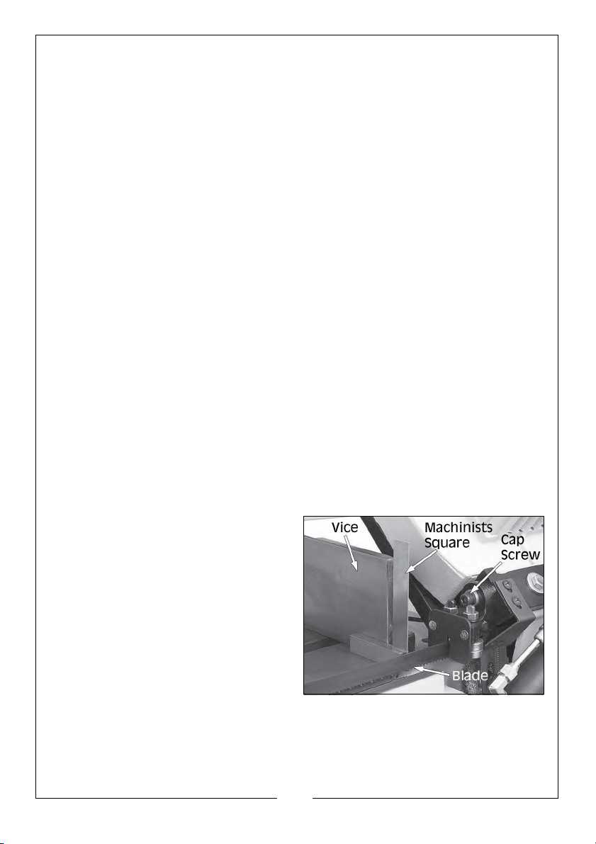
6. Adjust set screw with a 4mm hex wrench, then tighten hex bolt loosened in
step 4.
NOTE: Tightening the set screw will move the blade closer to the shoulder
of the wheel.
NOTE: Loosening the set screw will move the blade away from the
shoulder.
7. Re-tension the blade as set out on page 27.
8. Reconnect the machine to the power source and turn the bandsaw on.
NOTE: If the blade tracks along the shoulder of the wheel (without
rubbing), the blade is tracking properly and this adjustment is
complete.
NOTE: If the blade walks away from the shoulder of the wheel or hits the
shoulder, repeat sets 4 - 7 until the blade tracks correctly.
9. Turn off the bandsaw.
10. Replace the blade guard and wheel access cover.
SQUARING THE BLADE
It is always a good idea during the life of your saw to check and adjust this
setting. This adjustment will improve your cutting results and extend the life of
the blade.
TO SQUARE THE BLADE TO THE BED OF THE TABLE.
1. Disconnect the machine from the power source.
2. Lower the head of the bandsaw until it contacts the horizontal stop.
3. Place a square on the table bed
and against the edge of the
blade as shown, and check the
different points along the length
of the table between the blade
guides.
4. Loosen the cap screw shown, and
rotate the blade guide until the
blade is vertical to the bed.
NOTE: Both the blade guides can
be adjusted to achieve the
results you want.
5. Tighten the cap screw.
29
Parts & Service: 020 8988 7400 / E-mail: [email protected] or [email protected]
Page 30
BLADE GUIDE BEARINGS
The blade guide bearings come adjusted from the factory and the need for
adjustment should rarely occur. Uneven blade wear and crooked cuts may be
the results of improper adjustment.
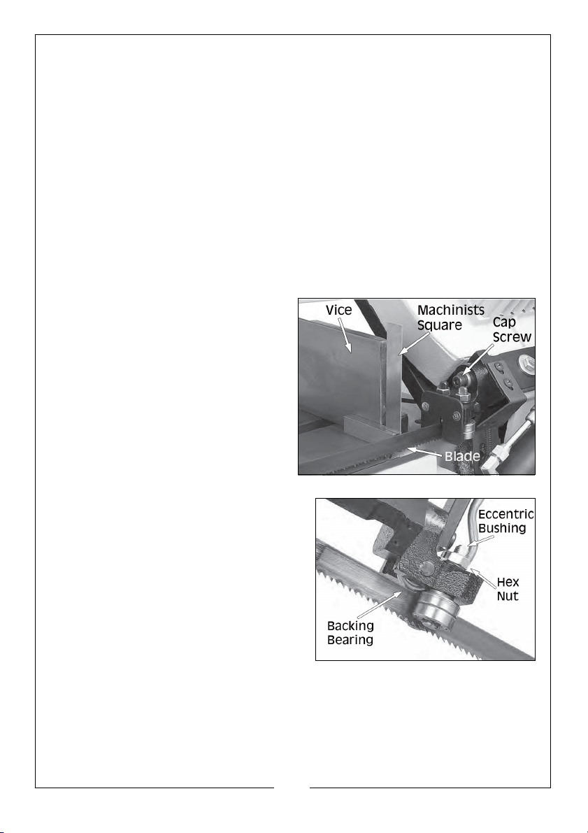
Each bearing assembly has an eccentric bushing that allows the distance
between the blade and bearings to be adjusted. The bearings are secured in
place by a hex nut and a lock washer.
Before adjusting the blade guide bearings, make sure that you have squared
the blade to the table as set out above.
TO ADJUST BLADE GUIDE BEARINGS
1. Disconnect the machine from the power source.
o
2. Position the vice to 90
3. Put a machinist’s square against
the face of the vice and move it
over to the blade. The square
should evenly touch both the
face of the vice and the blade. If
it does, skip to step 6, if the square
does not evenly touch the blade,
but does evenly touch the vice,
continue with the next step.
, then lock in place.
4. Loosen the hex nuts that secure the
eccentric bushings attached to the
guide bearings.
5. Adjust the bearings as necessary to
o
force the blade to 90
to the vice,
then tighten the hex nuts attached
to the bearings that are forcing the
o
blade to 90
.
6. Check to see if any bearings are not
touching the blade evenly. If so
loosen the hex nuts and adjust eccentric bushing so the contact surface of
the bearing touches the blade evenly.
30
Parts & Service: 020 8988 7400 / E-mail: [email protected] or [email protected]
Page 31

NOTE: Since the bearings twist the blade into position, it is acceptable if
there is 0.025mm - 0.050mm of a gap between the blade and the
front or back of the bearing. Just make sure not to squeeze the
blade too tightly with the bearings. After the guide bearings are
set, you should be able to rotate the guide bearings (although
they will be stiff) with your fingers.
The backing bearing is not adjustable and should make light contact with the
blade.
STORAGE
When storing the bandsaw, disconnect the power cable, cover the machine
with a plastic sheet and store it in a dry location.
REPLACEMENT BLADES & SUNDRIES
Replacement blades and sundries are available from your CLARKE dealer;
Blade (10tpi) 1 per pack Part no 1600772
Blade (24tpi) 1 per pack Part no 1600771
CLARKE cutting fluid ref: 1 Litre Part no 3051059
CLARKE cutting fluid ref: 5 Litre Part no 3051061
31
Parts & Service: 020 8988 7400 / E-mail: [email protected] or [email protected]
Page 32

TROUBLESHOOTING
Bandsaw Operations
Problem Check Solution
Excessive blade
breakage
Premature blade
dulling
Unusual wear on
side/back of
blade
Teeth ripping from
blade
1. Material loose in vice.
2. Incorrect speed or feed.
3. Blade pitch too great.
4. Material too hard.
5. Incorrect blade tension.
6. Teeth touching work before
start-up.
7. Blade rubs on wheel flange.
8. Mis-aligned guide bearings.
1. Teeth too coarse.
2. Speed too great.
3. Inadequate feed pressure.
4. Hard spots/scale on
material.
5. Work hardening of material.
6. Blade twist.
1. Blade guides worn.
2. Blade guide bearings not
adjusted correctly.
3. Blade guide bearing.
bracket loose.
1. Teeth too coarse for work.
2. Too slow speed.
3. Vibrating workpiece.
4. Teeth clogging.
1. Clamp work securely.
2. Adjust speed or feed.
3. Replace with finer.
toothed blade.
4. Select a slower speed
and finer toothed
blade.
5. Adjust blade tension.
6. Place blade in contact.
with work after motor
has started.
7. Adjust wheel alignment.
8. Adjust guide bearings.
1. Use finer tooth blade.
2. Reduce speed.
3. Reduce spring tension
on side of saw.
4. Reduce speed/increase
feed pressure.
5. Increase feed pressure
by reducing spring
tension.
6. Replace with a new
blade & adjust tension.
1. Replace guides.
2. Adjust bearings.
3.Tighten bracket.
1. Use finer tooth blade.
2. Reduce pressure
/ increase speed.
3. Clamp workpiece.
securely.
4. Use coarser blade or
brush away swarf.
32
Parts & Service: 020 8988 7400 / E-mail: [email protected] or [email protected]
Page 33
Motor running too
hot
1. Blade tension too high.
2. Drive belt too tight.
3. Gears need lubrication.
4. Blade is binding.
Bad cuts (not
1. Feed pressure too great.
cutting square)
2. Guide bearing not adjusted
properly.
3. Inadequate blade tension.
4. Dull blade.
5. Speed incorrect.
6. Blade guides too far apart.
7. Blade guide assembly loose
8. Blade tracks too far away
from wheel flanges.
Bad cuts (rough) 1. Too great a speed of feed.
2. Blade is too coarse.
3. Blade tension slack.
Blade is twisting 1. Blade is binding.
2. Too much blade tension.
1. Reduce blade tension.
2. Reduce drive belt
tension.
3. Check oil bath.
4. Decrease feed speed.
1. Reduce pressure by
increasing spring tension
of the saw.
2. Adj guide bearing
clearance not greater
than 0.025mm.
3. Increase blade tension.
4. Replace blade.
5. Adjust speed.
6. Adjust guides space.
7. Tighten.
8. Check and adjust blade
tracking.
1. Decrease speed of feed
2. Replace with finer
blade.
3. Adjust blade tension.
1. Decrease feed pressure
2. Decrease blade tension
Motor & Electrical
Problem Check Solution
Machine does
not start or a
breaker trips.
Parts & Service: 020 8988 7400 / E-mail: [email protected] or [email protected]
1. Plug is at fault/wired
incorrectly.
2. Power supply is at fault/
switched OFF.
3. Motor wired incorrectly.
4. Start capacitor is at fault.
5. Fuse/circuit breaker is
blown/tripped.
6. Motor ON/OFF switch is at
fault.
7. Wiring open/has high
resistance.
8. Motor is at fault.
33
1. Test for good contacts,
correct wiring.
2. Ensure power supply is
switched ON.
3. Correct motor wiring.
4. Test/replace capacitor.
5. Ensure correct size of
fuse for the machine load,
replace weak breaker.
6. Replace faulty ON/OFF
switch.
7. Check/fix broken,
disconnected or corroded
wires.
8. Test/Repair/Replace.
Page 34

Machine stalls or
is underpowered
Machine has
vibration or noisy
operation
1. Wrong Blade for workpiece
material.
2. Wrong workpiece material.
3. Feed rate/cutting speed
too fast for task.
4. Blade is slipping on wheels.
5. Low power supply voltage.
6. Motor bearings are at fault.
7. Plug is at fault.
8. Motor connection is wired
incorrectly.
9. Motor has overheated.
10. Motor is at fault.
1. Motor fan is rubbing on fan
cover.
2. Blade is at fault.
3. Gearbox is at fault.
4. Wrong blade and/or speed
too slow.
1. Use blade with correct
properties for your type of
cutting.
2. Use metal with correct
properties for your type of
cutting.
3. Decrease feed rate/
cutting speed.
4. Adjust blade tracking
and tension.
5.Make sure the power
source is set for correct
voltage.
6. Test by rotating shaft.
Rotational grinding/loose
shaft requires bearing
replacement.
7. Test for good contacts,
correct the wiring.
8. Correct motor wiring
connections.
9. Clean off motor, let cool
and reduce workload.
10. Test/Repair/Replace.
1. Replace dented fan
cover; replace loose/
damaged fan.
2. Replace/resharpen
blade.
3.Rebuild gearbox and
replace bad gear(s)/
bearing(s).
4. Change blade and/or
speed.
34
Parts & Service: 020 8988 7400 / E-mail: [email protected] or [email protected]
Page 35
PARTS LIST & DIAGRAM
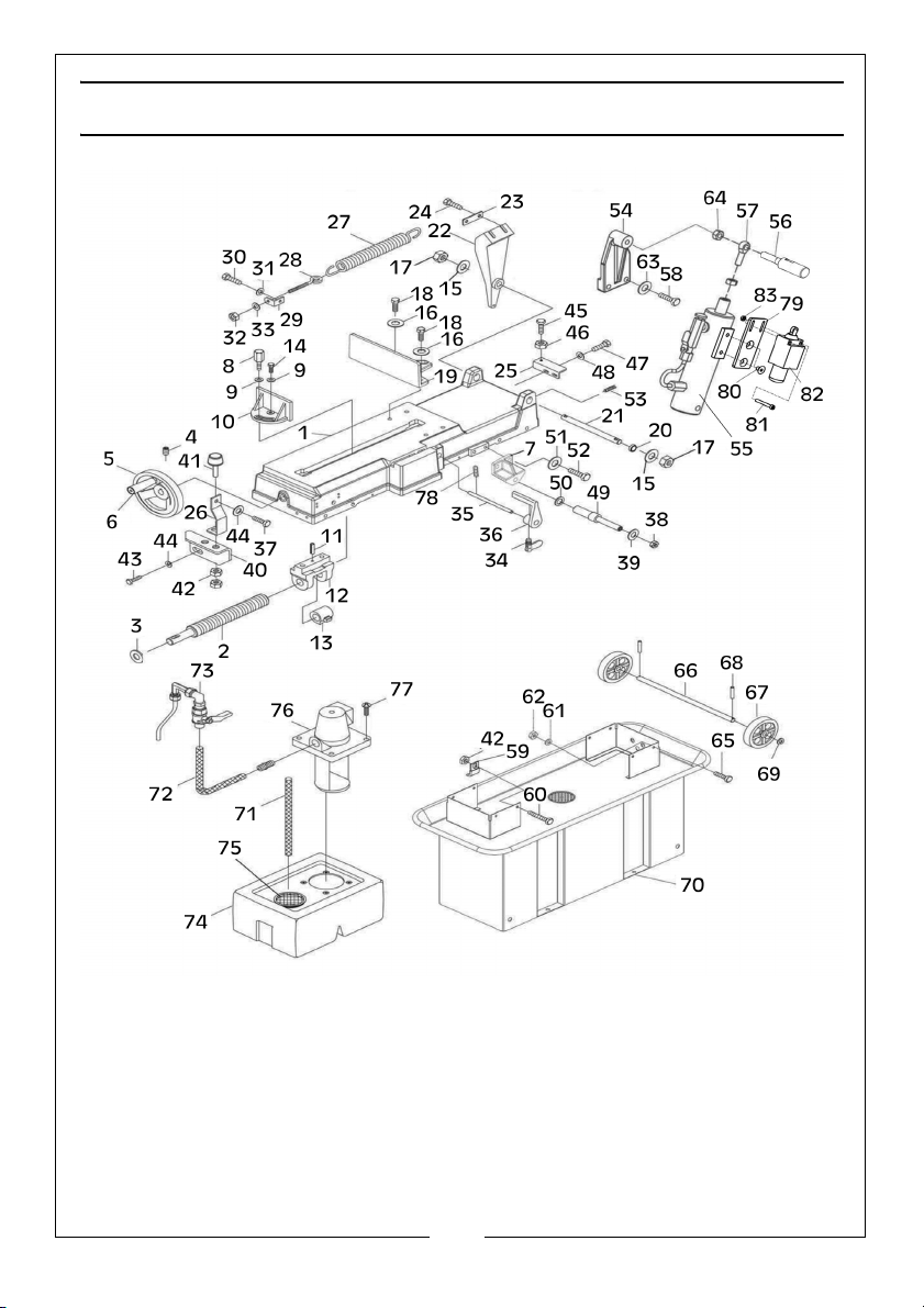
NO DESCRIPTION NO DESCRIPTION
Parts Diagram A 32 Nut M10
1Table 33Washer
2 Adjusting Screw 34 Lock Bolt
3 Spacer 35 Work Stop Rod
4Set Screw M6 x10 36Work Stop
5 Wheel 37 Screw M6 x 12
6 Wheel Handle 38 Lock Nut M10
7 Support Bracket 39 Washer
8 Dragging Handle 40 Support Plate
9 Washer 10 41 Buffer Block
10 Vice Jaw Bracket (Rear) 42 Nut M8
11 Spring Pin 6 x 20 43 Hex Bolt M8 x 16
12 Bracket 44 Washer
13 Quick Nut 45 Hex Bolt M8 x 25
14 Hex Bolt M10 x 35 46 Nut M8
15 Washer 16 47 Hex Bolt M8 x 16
16 Washer 12 48 Washer
17 Lock Nut M16 49 Cylinder Support Rod
18 Hex Bolt M12 x 35 50 Washer
19 Vice Jaw Bracket (Front) 51 Washer 10
20 Bushing 52 Bolt M10 x 30
21 Support Rod 53 Set Screw M8 x 12
22 Pivot Bracket 54 Cylinder Bracket
23 Plate 55 Hydraulic Cylinder
24 Hex Bolt M10 x 35 56 Special Bolt
25 Support Plate 57 Joint Bearing
26 Fixed Plate 58 Hex Bolt M8 x 30
27 Spring 59 Keep Plate
28 Spring Adjusting Rod 60 Hex Bolt M8 x 30
29 Spring Handle Bracket 61 Washer
30 Hex Bolt M8 x 16 62 Nut M8
31 Washer 8 63 Washer
35
Parts & Service: 020 8988 7400 / E-mail: [email protected] or [email protected]
Page 36
NO DESCRIPTION NO DESCRIPTION
64 Nut M10 99 Drive Wheel
65 Hex Bolt M8 x 30 100 Sliding Plate
66 Wheel Rod 101 Blade Tension Sliding Block
67 Wheel 102 Set Screw M8 x 20
68 Cotter Pin 2.5 x 25 103 Hex Bolt M8 x 40
69 Washer 104 Washer
70 Coolant Frame 105 Washer
71 Hose 106 Hex Bolt M6 x 16
72 Hose 107 Spring
73 Nozzle Cock 108 Blade Adjusting Knob
74 Coolant Tank 109 Wheel Shaft Assembly
75 Swarf Filter Screen 110 Idler Wheel Seat
76 Cooling Pump 111 Cotter Pin 5 x 22
77 Pan Head Screw M6 x 12 112 Wheel Shaft
78 Set Screw M6 x 12 113 Spacer
79 Switch Bracket 114 Bearing 6203
80 Sunk Head Screw M6 x 8 115 Circlip
81 Hex Screw M4 x 30 116 Washer
82 Limit Switch 117 Hex Bolt M8 x 16
83 Nut M4 118 Idler Wheel
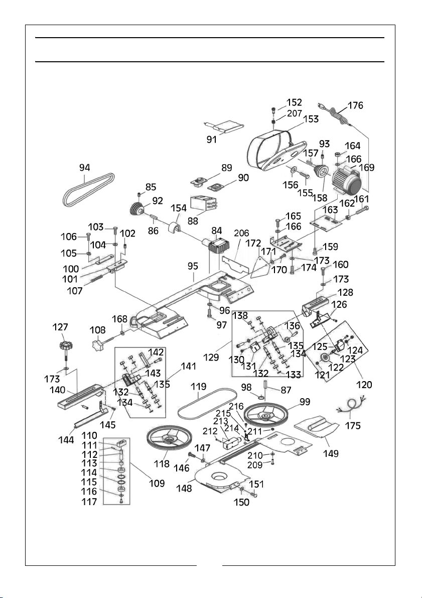
Parts Diagram B 119 Blade 0.9 x 19 x 2360
84 Gearbox Assembly(see diag C) 120 Brush Assembly
85 Set Screw M8 x 12 121 Lock Nut M8
86 Key 5 x 5 x 30 122 Brush
87 Key 6 x 6 x 20 123 Brush Shaft
88 Electrical Box 124 Washer
89 Main Switch 125 Brush Bracket
90 Pump Switch 126 Blade Cover, Rear
91 Pulley Cover Micro Switch 127 Knob Bolt
92 Spindle Pulley 128 Adjusting Bracket, Rear
93 Set Screw M8 x 10 129 Guide Block Assembly, Rear
94 Drive-Belt 660 130 Sunk Head Screw
95 Body Frame 131 Splash Guard
96 Washer 132 Eccentric Shaft
97 Hex Bolt M10 x 35 133 Circlip for Shaft
98 Spacer 134 Bearing
36
Parts & Service: 020 8988 7400 / E-mail: [email protected] or [email protected]
Page 37
NO DESCRIPTION NO DESCRIPTION
135 Bearing Shaft 171 Washer
136 Pin 172 Support Plate
137 Washer 173 Washer
138 Lock Nut M8 174 Hex Bolt M8 x 25
139 Guide Block, Rear 175 Power Switch Cable
140 Adjust Bracket, Front 176 Power Cable
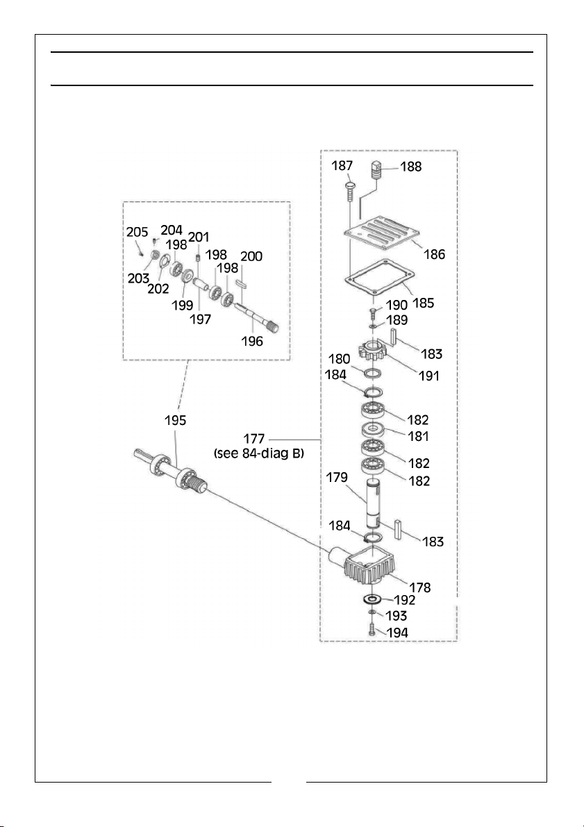
141 Guide Block Assembly, Front Parts Diagram C
142 Bracket for Hole 177 Gearbox Assembly
143 Guide Block, Front 178 Gearbox Housing
144 Blade Cover, Front 179 Transmission Wheel Shaft
145 Screw M5 x 10 180 Spacer
146 Screw M6 x 12 181 Oil Seal 25 x 47 x 10
147 Washer 182 Ball Bearing 6005
148 Blade Back Cover 183 Key 6 x 6 x 20
149 Drive Wheel Cover 184 External Retaining Ring 25mm
150 Washer 185 Gearbox Gasket
151 Pan Head Screw M6 x 12 186 Gearbox Cover
152 Closing Bolt 187 Hex Bolt M6 x 12
153 Motor Pulley Cover 188 Vent Plug
154 Shaft Cover 189 Washer
155 Screw M6 x 10 190 Hex Bolt M8 x 16
156 Washer 191 Worm Gear
157 Key 6 x 6 x 25 192 Special Washer
158 Motor Pulley 193 Spring Washer
159 Hex Bolt M8 x 25 194 Hex Bolt M10 x 25
160 Hex Bolt M10 x 30 195 Worm Gear Shaft Assembly
161 Hex Bolt M8 x 60 196 Worm Shaft
162 Nut M8 197 Bearing Bushing
163 Motor Mount 198 Ball Bearing 6003
164 Nut M8 199 Oil Seal 17 x 35 x 7
165 Hex Bolt M8 x 16 200 Key 5 x 5 x 30
166 Washer 201 Set Screw M10 x 16
167 Motor Mount Bracket 202 Bearing Cover
168 Washer 203 Spacer
169 Motor 204 Set Screw M8 x 10
170 Screw M6 x 12 205 Screw M5 x 10
37
Parts & Service: 020 8988 7400 / E-mail: [email protected] or [email protected]
Page 38

NO DESCRIPTION NO DESCRIPTION
Parts Diagram B Additions
206 End Plate 212 Screw
207 Nut 213 Switch
208 Pin 214 Switch Bracket
209 Bolt 215 Nut
210 Washer 216 Screw
211 Nut
38
Parts & Service: 020 8988 7400 / E-mail: [email protected] or [email protected]
Page 39
Page 40
Page 41
Page 42

DECLARATION OF CONFORMITY - UKCA
42
Parts & Service: 020 8988 7400 / E-mail: [email protected] or [email protected]
Page 43

DECLARATION OF CONFORMITY - CE
43
Parts & Service: 020 8988 7400 / E-mail: [email protected] or [email protected]
Page 44

 Loading...