

Page 1
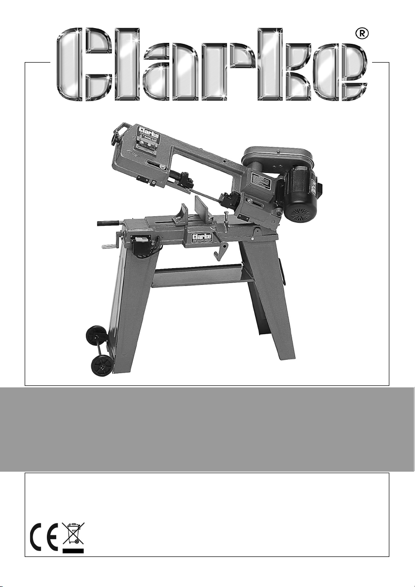
6” BANDSAW
MODEL NO: CBS45MD
PART NO: 6460060
OPERATION & MAINTENANCE
INSTRUCTIONS
ORIGINAL INSTRUCTIONS
GC0614 - ISS 5
Page 2

INTRODUCTION
Thank you for purchasing this CLARKE Bandsaw.
Before attempting to operate the machine, it is essential that you read this
manual thoroughly and carefully follow all instructions given. In doing so you
will ensure the safety of yourself and that of others around you, and you can
also look forward to the product giving you long and satisfactory service.
GUARANTEE
This CLARKE product is guaranteed against faulty manufacture for a period of
12 months from the date of purchase. Please keep your receipt as proof of
purchase.
This guarantee is invalid if the product is found to have been abused or
tampered with in any way, or not used for the purpose for which it was
intended.
Faulty goods should be returned to their place of purchase, no product can
be returned to us without prior permission.
This guarantee does not effect your statutory rights.
ENVIRONMENTAL PROTECTION
Recycle unwanted materials instead of disposing of them as waste. All
unwanted accessories and packaging should be sorted and taken to a
recycling centre for disposal in a manner which is compatible with the
environment.
ENVIRONMENTAL RECYCLING POLICY
Through purchase of this product, the customer is taking on the
obligation to deal with the WEEE in accordance with the WEEE
regulations in relation to the treatment, recycling & recovery and
environmentally sound disposal of the WEEE.
In effect, this means that this product must not be disposed of with general
household waste but according to the laws governing Waste Electrical and
Electronic Equipment (WEEE) at a recognised disposal facility.
2
Parts & Service: 020 8988 7400 / E-mail: [email protected] or [email protected]
Page 3

SAFETY WARNINGS
CAUTION: FAILURE TO FOLLOW THESE PRECAUTIONS COULD RESULT IN
PERSONAL INJURY, AND/OR DAMAGE TO PROPERTY.
WORK ENVIRONMENT
1. Keep the work area clean and well lit. Cluttered and dark areas invite
accidents.
2. Do not operate power tools in explosive atmospheres, such as in the
presence of flammable liquids, gases or dust. Power tools create sparks
which may ignite the dust or fumes.
3. Keep children and bystanders away while operating a power tool. Anyone
entering the work area must wear personal protective equipment.
Distractions can cause you to lose control and fragments of work or a
broken disc may fly away and cause injury.
4. Store power tools properly when not in use. Abrasive products should be
stored in a dry, secure place out of the reach of children.
5. Please read these instructions carefully and retain for future reference.
ELECTRICAL SAFETY
1. Power tool plugs must match the outlet. Never modify the plug in any way.
Do not use adapter plugs with earthed (grounded) power tools. Unmodified
plugs and matching outlets will reduce the risk of electric shock.
2. Do not expose power tools to rain or wet conditions. Water entering a
power tool will increase the risk of electric shock.
3. Do not abuse the cable. Never use the cable for carrying, pulling or
unplugging the power tool. Keep the cable away from heat, oil, sharp
edges or moving parts. Damaged or entangled cables increase the risk of
electric shock.
4. When operating a power tool outdoors, use an extension cable suitable for
outdoor use. Use of a cable suitable for outdoor use reduces the risk of
electric shock.
PERSONAL SAFETY
1. Stay alert, watch what you are doing and use common sense when
operating a power tool. Do not use a power tool while you are tired or
under the influence of drugs, alcohol or medication. A moment of
inattention while operating power tools may result in personal injury.
3
Parts & Service: 020 8988 7400 / E-mail: [email protected] or [email protected]
Page 4

2. Use personal protective equipment. Always wear eye protection. Safety
equipment such as dust mask, non-skid safety shoes, hearing protection
and a workshop apron capable of stopping small abrasive or workpiece
fragments.
3. Avoid accidental starting. Ensure the switch is in the off position before
plugging in. Plugging in power tools that have the switch on invites
accidents.
4. Remove any adjusting key or wrench before turning the power tool on. A
wrench or a key left attached to a rotating part of the power tool may
result in personal injury.
5. Do not overreach. Keep proper footing and balance at all times. This
enables better control of the power tool in unexpected situations. Dress
properly. Do not wear loose clothing or jewellery.
6. Keep your hair, clothing and gloves away from moving parts. Loose
clothes, jewellery or long hair can be caught in moving parts. Keep the
work area clean and tidy.
7. Regularly clean the power tool’s air vents. The motor fan will draw dust
inside the housing and accumulation of material could cause electrical
hazards.
8. Avoid operator fatigue. Stop the power tool at regular intervals for a short
break to rest hands and arms.
9. Maintain your tools. Keep all handles and grips dry and clean.
ELECTRICAL SAFETY
1. Position the power cable so that it cannot be inadvertently pulled or
pinched, and where it does not cause a trip hazard.
2. This machine is designed for indoor environments and must not be used for
other purposes.
3. If the machine requires repair, always contact your Clarke dealer. Always
insist on original spare parts. Repairs carried out by unauthorized persons
may be dangerous and invalidate the guarantee.
4. This machine must only be used by adults. Children should not be allowed
to play with this product.
5. Do not use extension power cables.
6. Before cleaning or maintenance tasks, always unplug the machine from
the power supply.
POWER TOOL USE AND CARE
1. Do not force the machine. Use the correct power tool for your application.
It will do a better and safer job at the rate for which it was designed.
4
Parts & Service: 020 8988 7400 / E-mail: [email protected] or [email protected]
Page 5

2. Do not use the power tool if the switch does not turn it on and off. Any
power tool that cannot be controlled with the switch is dangerous and
must be repaired.
3. Disconnect the power tool from the power supply before making any
adjustments, changing accessories, or storing the tool. These measures will
reduce the risk of the power tool starting accidently.
4. Store power tools out of the reach of children and do not allow persons
unfamiliar with these instructions to operate the power tool. Power tools are
potentially dangerous in the hands of untrained users.
5. Maintain power tools in top condition. Keep tools/ machines clean for the
best and safest performance. Check for misalignment or binding of
moving parts, broken parts, or any condition that may affect the power
tool’s operation. If damaged, have the power tool repaired before use.
Many accidents are caused by poorly maintained power tools.
6. Use recommended accessories. The use of improper accessories could be
hazardous.
7. Machine cleanliness. Do not allow the ventilation slots in the machine to
become blocked with dust.
8. Check the power tool for damage before using the machine. Any
damaged part should be inspected to ensure that it will operate properly
and perform its intended function. Check for alignment of moving parts,
breakage of parts, mountings, and any other condition that may affect the
machine’s operation. Any damage should be properly repaired or the part
replaced. If in doubt, DO NOT use the machine. Consult your local dealer.
SERVICING
1. When necessary, have your power tools serviced or repaired by a qualified
person using identical replacement parts. This will ensure that the safety of
the power tool is maintained.
ADDITIONAL PRECAUTIONS FOR BANDSAWS
1. Always check safety guards are in place and functioning correctly before
switching the machine on.
2. Always use a push stick, especially on small workpieces.
3. Always use the appropriate saw blade for the material being cut.
4. Never use the machine if the electric cable, plug or motor is in poor
condition.
5. Never allow the ventilation slots in the motor to become blocked.
6. Never touch the blade immediately after use, when changing the blade
always allow time for it to cool.
5
Parts & Service: 020 8988 7400 / E-mail: [email protected] or [email protected]
Page 6
7. Never use bent or cracked blades. (Replacement blades are available
from your Clarke dealer.
8. When cutting wood, ensure all nails or fastenings have been removed
beforehand.
9. When cutting round stock, use a suitable jig or fixture to keep the work from
turning.
10. Always ensure the blade is fully tightened and correctly adjusted before
use.
11. Keep the mains power cable well away from the machine and ensure an
adequate electrical supply is close at hand so that the operation is not
restricted by the length of the cable.
12. Switch the machine off immediately the task is completed.
SPECIFICATIONS
Weight 64 kg
Dimensions (W x H x D) 1100 x 960 x 1500 mm
Table Height from Floor 610 mm
Tilt angle
Maximum Cutting capacity@90
o
Blade Speed (3 speeds) 20, 29, 50 m/min
Blade Size 1638 x 12.7 x 0.65 mm - 14 tpi
Supply Cable Length 2000 mm
Sound Power Level Measured (Lw) less than 78 dB(A) whilst cutting
o
0 - 45
Round section 100 mm
Flat 100 x 150 mm
6
Parts & Service: 020 8988 7400 / E-mail: [email protected] or [email protected]
Page 7
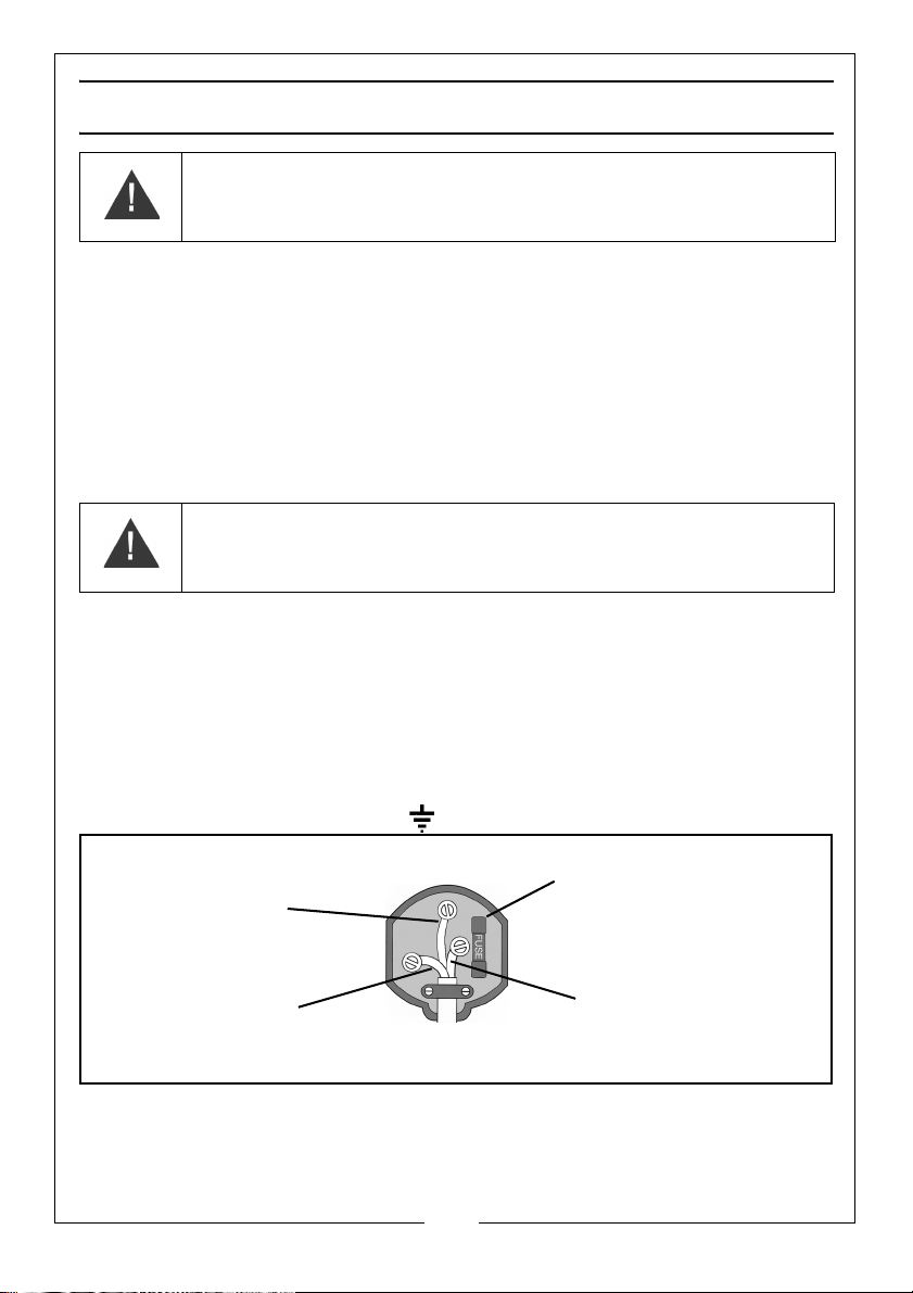
ELECTRICAL CONNECTIONS
Plug must be BS1363/A approved.
Always fit a 13 Amp fuse.
Ensure that the outer sheath of the cable is firmly held by the clamp
Neutral
(Blue)
Live
(Brown)
Earth
(Green and Yellow)
WARNING! Read these electrical safety instructions thoroughly
before connecting the product to the mains supply.
Before switching the product on, make sure that the voltage of your electricity supply is
the same as that indicated on the rating plate. This product is designed to operate on
230VAC 50Hz. Connecting it to any other power source may cause damage.
This product may be fitted with a non-rewireable plug. If it is necessary to change the
fuse in the plug, the fuse cover must be refitted. If the fuse cover becomes lost or
damaged, the plug must not be used until a suitable replacement is obtained.
If the plug has to be changed because it is not suitable for your socket, or due to
damage, it should be cut off and a replacement fitted, following the wiring instructions
shown below. The old plug must be disposed of safely, as insertion into a mains socket
could cause an electrical hazard
WARNING! The wires in the power cable of this product are
coloured in accordance with the following code:
Blue = Neutral Brown = Live Yellow and Green = Earth
If the colours of the wires in the power cable of this product do not correspond with the
markings on the terminals of your plug, proceed as follows.
• The wire which is coloured Blue must be connected to the terminal which is
marked N or coloured Black.
• The wire which is coloured Brown must be connected to the terminal which
is marked L or coloured Red.
• The wire which is coloured Yellow and Green must be connected to the
terminal which is marked E or or coloured Green.
.
We strongly recommend that this machine is connected to the mains supply via a Residual
Current Device (RCD)
If in any doubt, consult a qualified electrician. DO NOT attempt any repairs yourself.
Parts & Service: 020 8988 7400 / E-mail: [email protected] or [email protected]
7
Page 8
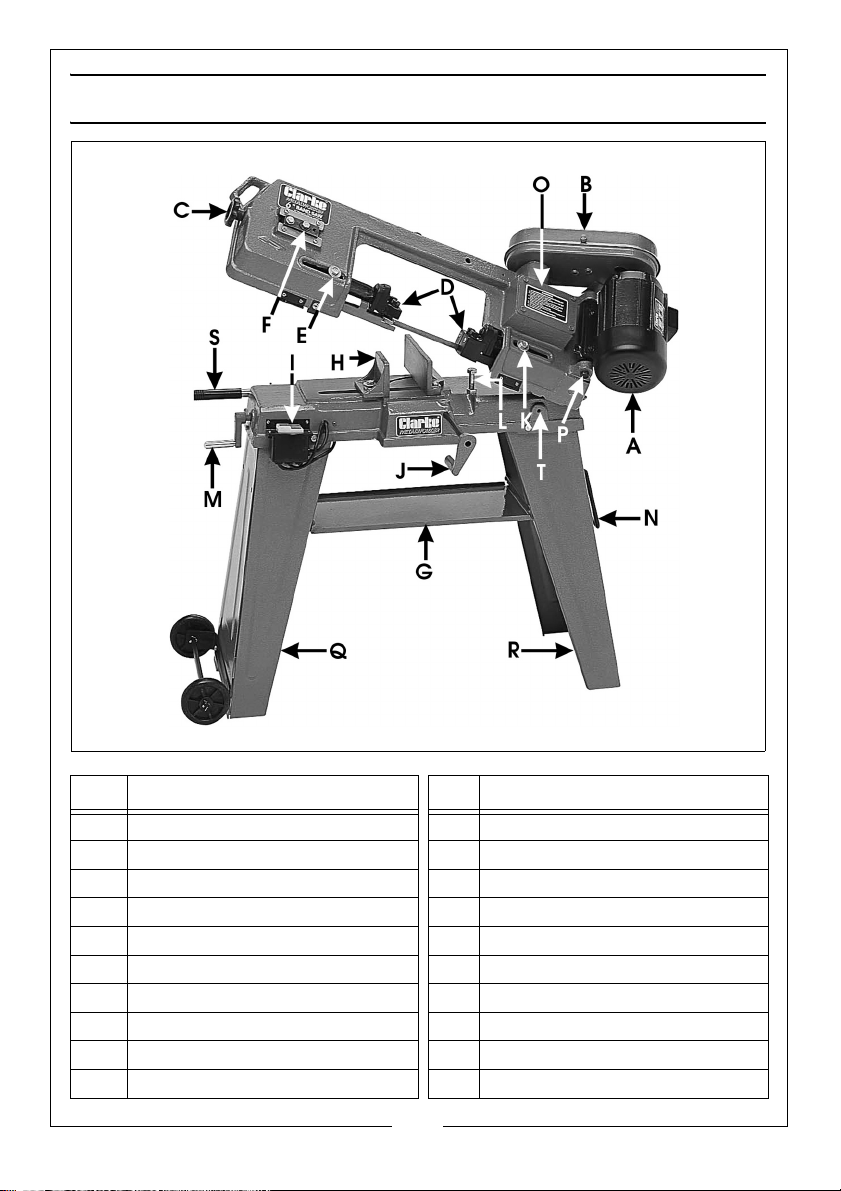
OVERVIEW
Item Description Item Description
A Motor K Blade Guide Carrier Lock Bolt
B Drive Guard L Stop Bolt
C Blade Tension Adjusting Knob M Vice Jaw Adjuster
D Blade Guides N Manoeuvring Handle
E Blade Guide Carrier Lock Bolt O Gearbox
F Blade Tracking Adjuster P Drive Belt Tensioning Bolt
G Tool Tray Q Left Leg
H Adjustable Vice Jaw R Right Leg
I ON/OFF Switch Box S Arm Weight Adjuster
J Work Stop Assembly T Vertical Locking Bracket
8
Parts & Service: 020 8988 7400 / E-mail: [email protected] or [email protected]
Page 9
ASSEMBLY
The bandsaw comes partly assembled. Unpack and lay out all the items and
identify each one, referring to the overview on page 8.
If any parts are missing, immediately contact the dealer where the product
was purchased.
CAUTION: IF THERE IS ANY UNCERTAINTY REGARDING ELECTRICAL
CONNECTIONS, YOU SHOULD CONSULT A QUALIFIED ELECTRICIAN.
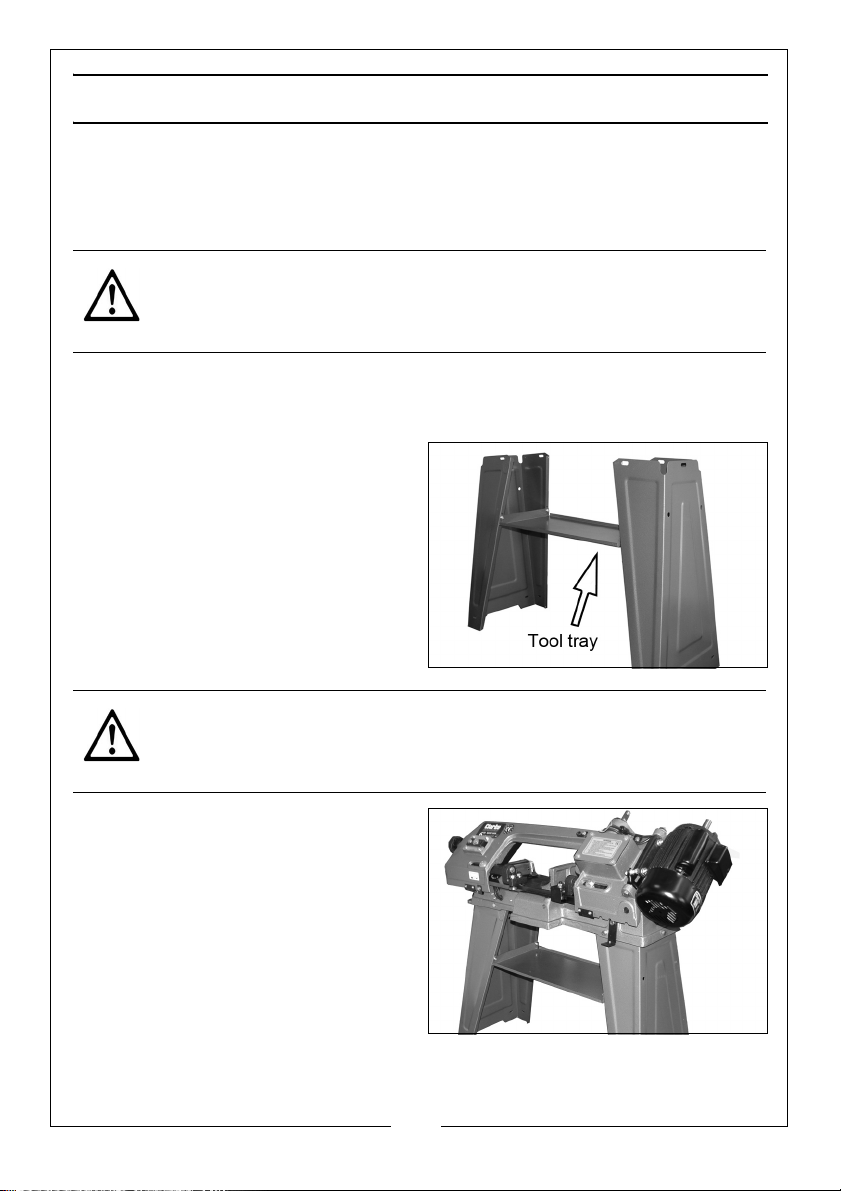
LEGS AND TOOL TRAY ASSEMBLY
• The legs are a three sided section, one side of which is hinged.
1. Attach the tool tray between the
legs, as shown, (i.e. tray edges
uppermost), using the four nuts,
bolts and washers supplied. Leave
the nuts finger tight at this stage.
NOTE: The special “D” shaped
washer should be inside the
leg with the nut.
2. Gently lower the bandsaw onto
the legs.
CAUTION: TWO PEOPLE WILL BE REQUIRED FOR THIS TASK
3. Secure the bandsaw to the legs
using three nuts, bolts and
washers at the top of each leg.
Make sure there is no distortion.
NOTE: The machine bed may fit
either way round.
4. Tighten all the tray nuts and bolts,
checking for distortion and
stability.
9
Parts & Service: 020 8988 7400 / E-mail: [email protected] or [email protected]
Page 10
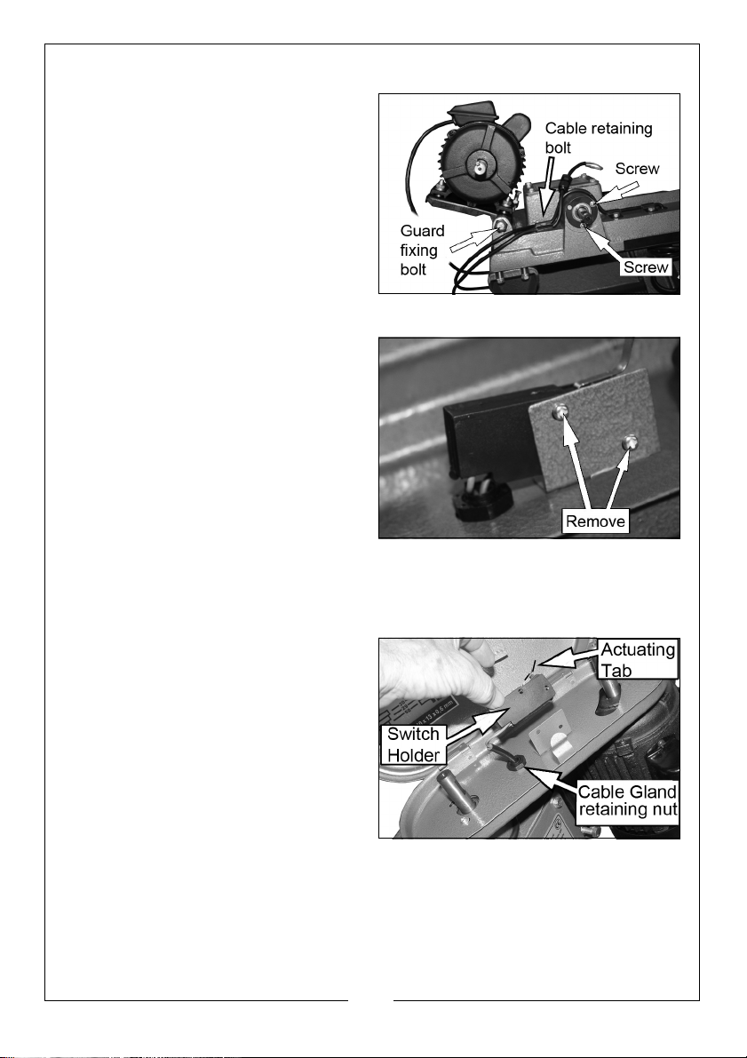
DRIVE GUARD
The drive guard sits over the motor
shaft, and the gear-box shaft. The
gearbox shaft extends through a
circular plate secured by three
screws.
1. Remove two of the screws
(arrowed) and the guard fixing
bolt.
2. Lower the drive guard over the
shafts. The elongated hole is
placed over the motor shaft.
3. Replace the screws and the
guard fixing bolt to secure the
drive guard.
SAFETY SWITCH
For safety purposes, a micro-switch is
provided to stop the bandsaw when
the drive guard is opened. The switch
is mounted on the inside of the drive
guard, between the two pulleys. The
micro-switch is operated by an
actuating tab, so that when the lid is closed, the bandsaw will operate.
1. Remove the switch from its mounting by unscrewing the two mounting
screws and nuts.
2. Thread the wires through the hole
in the drive guard complete with
the cable gland provided, and
connect the two push-on
connectors to the micro-switch
terminals. Re-tighten the nut on
the cable gland.
3. Re-fit the switch to the holder
using the two mounting screws &
nuts. Do not overtighten.
4. Close the guard, switch on the machine, and check that the switch
operates correctly when the guard is opened and closed.
• It may necessary to bend the switch actuating tab slightly to ensure
correct operation.
10
Parts & Service: 020 8988 7400 / E-mail: [email protected] or [email protected]
Page 11
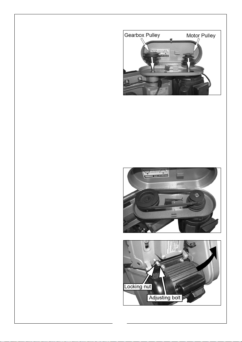
DRIVE PULLEYS
The drive pulleys may now be fitted.
• The motor pulley is located with a
key and grubscrew, and a
keyway is therefore provided in
the bore, whilst the gearbox
pulley has no keyway, and is
located with a grub-screw on a
flat surface milled on the shaft.
IMPORTANT: When fitting,they are
mounted in reverse to each other
as
shown on the lable inside the drive guard.
1. Fit the gearbox pulley onto its shaft, ensuring the grub screw lines up with
the flat on the shaft. Tighten the grub screw fully.
2. Fit the motor pulley to its shaft so that it lines up with the gearbox pulley. This
may be done with a straight edge across the top of the pulleys to ensure
the grooves are in line. When correctly aligned, tighten the grub screw
provided.
DRIVE BELT
1. Fit the drive belt, lifting the motor
and slipping the belt over the
pulleys.
• Belt tension is set by an adjusting
bolt through the motor mounting
plate.
2. Screw the bolt in until the belt can
be deflected by approx. ½” at
the centre of its span.
3. Lock the adjusting bolt using the
locking nut.
NOTE: Do not overtighten the
adjusting bolt as this will
distort the motor mounting
plate.
11
Parts & Service: 020 8988 7400 / E-mail: [email protected] or [email protected]
Page 12
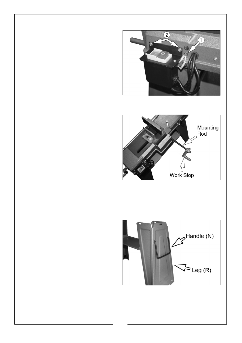
SWITCH ASSEMBLY
On the left end of the machine is the
ON/OFF switch assembly, which is
hanging loose at this stage.
1. Connect the two earth wires (1)
extending from the back of the
switch assembly to the machine
bed using the screw and washer
provided.
2. Mount the switch assembly using
the two screws (2).
WORK STOP ASSEMBLY
The work stop is used to cut pieces of
equal length without having to
measure each piece individually. It
comprises two parts, the work stop,
and the mounting rod.
1. Push the rod into the hole in the
edge of the vice and secure with
the bolt provided.
2. Mount the work stop on to the
rod, with the flat face towards the
saw blade, and temporarily secure with the grub-screw supplied. Ensure it is
not pushed on too far, as it may inter fere with the saw blade when the saw
is lowered.
HANDLE AND WHEELS
1. Fit the handle by passing the ends
of the handle through the
corresponding holes in the right
leg, and locating from inside the
leg using the split pins provided.
12
Parts & Service: 020 8988 7400 / E-mail: [email protected] or [email protected]
Page 13
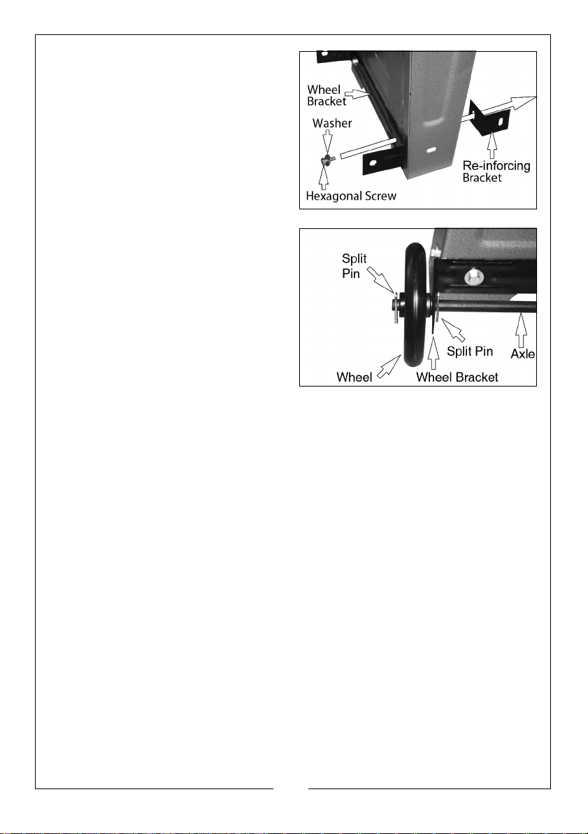
2. Attach the wheel bracket to the
base of the left leg using the nuts,
bolts and washers, together with a
pair of re-inforcing brackets fitted
inside the leg.
3. Pass the axle through the holes at
the ends of the bracket, and insert
the split pins into the holes in the
axle nearest the frame.
4. Fit the wheels to the axle and
secure with the remaining split
pins.
5. Add the two remainiing reinforcing brackets to the bottom
of the other legs.
6. Finally, carry out a thorough
check to ensure that all parts are
secure and correctly assembled.
When the machine is lifted using the
handle it will automatically pivot on the wheels, allowing the machine to be
maneuvered around the workshop.
13
Parts & Service: 020 8988 7400 / E-mail: [email protected] or [email protected]
Page 14
SETUP AND ADJUSTMENTS
BLADE GUIDE ADJUSTMENT
The blade guides must be correctly aligned for the bandsaw to perform at its
best.
When the saw is used correctly, adjustment is rarely needed. If, for any reason,
the guides do move out of alignment, you must re-adjust them immediately or
the blade will not cut straight and will be damaged.
Guide adjustment is critical to the performance of your saw but it Is always
best to try a new blade to see if this will correct poor cutting before adjusting
the bearings.
If a blade becomes dull on one side, it will begin cutting crooked. A new
blade should correct this problem without the need for guide adjustment. If
not, check the blade guides for accurate spacing.
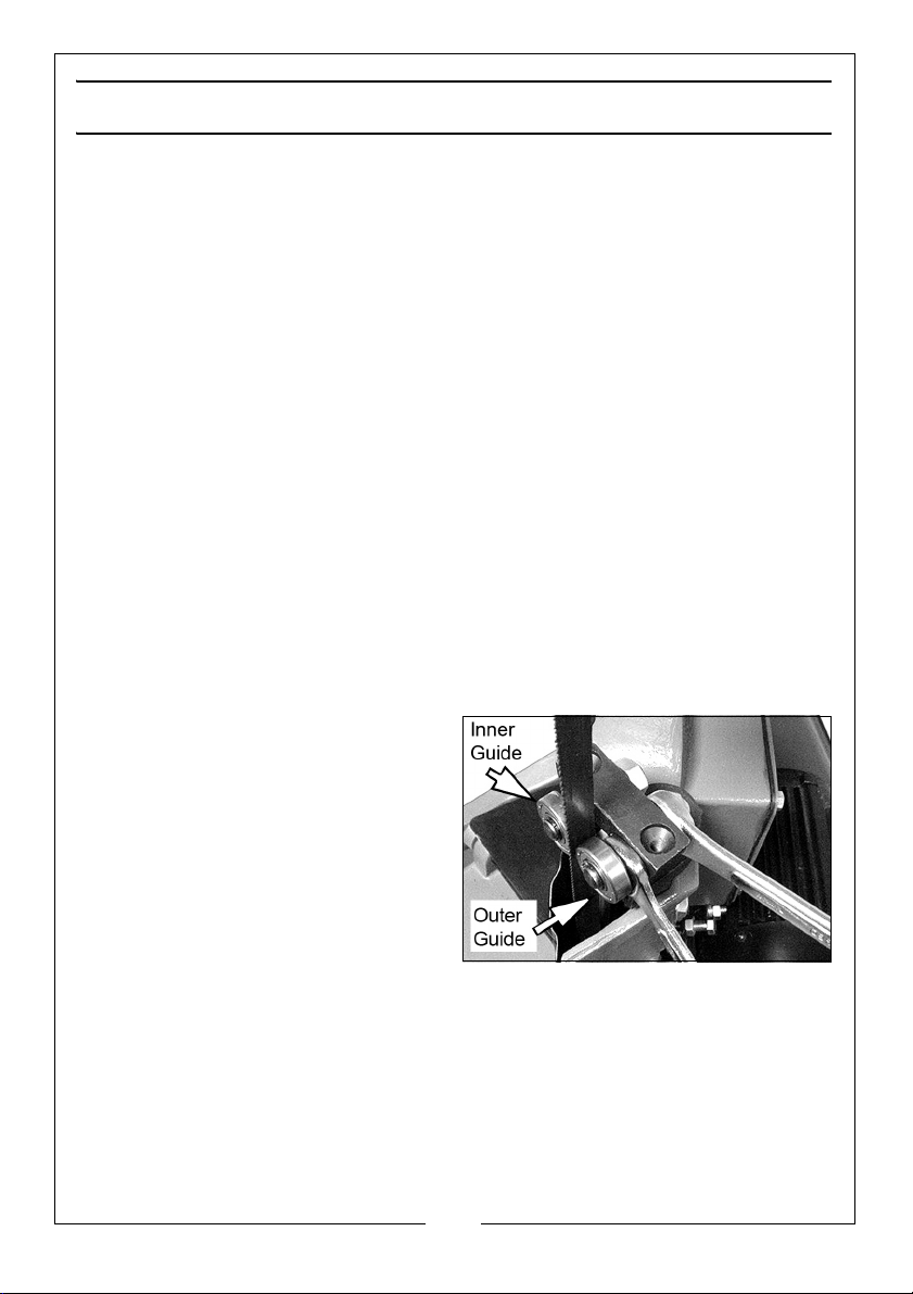
• The inner guide bearing is fixed and cannot be adjusted.
• The outer guide bearing is mounted to an eccentric bolt and can be
adjusted.
• There should be 0.001" clearance between a 0.025" thickness blade and
the guide bearings.
To obtain this clearance adjust the bearing as follows:
1. Loosen the nut whilst holding the
bolt with a second spanner as
shown.
2. Position the eccentric by turning
the bolt to the required position
before tightening the nut.
3. Adjust the other blade guide
bearing in the same way.
• The back edge of the blade
should just touch the blade guide
rear bearing.
BLADE GUIDE ASSEMBLY ADJUSTMENT
The blade guide assemblies are adjustable to accommodate the size of
workpiece. Correct adjustment will help accurate cutting and prolong the life
of the blade.
14
Parts & Service: 020 8988 7400 / E-mail: [email protected] or [email protected]
Page 15
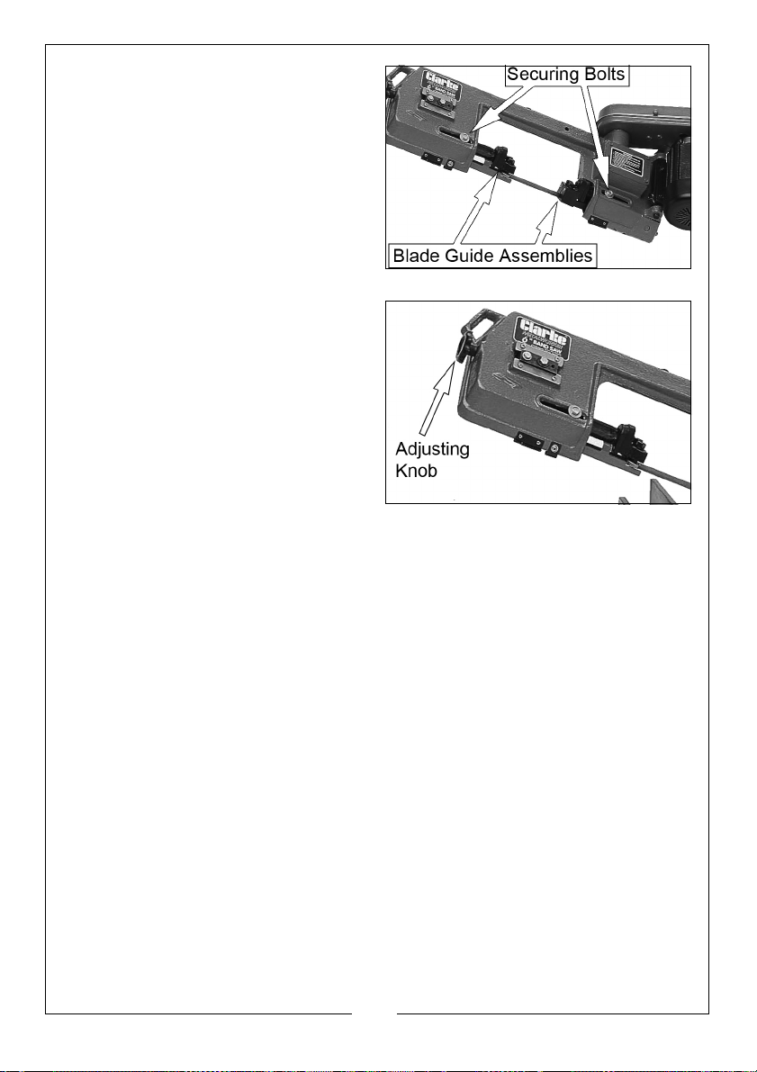
1. Place your workpiece in the vice
and clamp tightly.
2. Loosen the securing bolts.
3. Adjust each blade guide
assembly to just clear the
workpiece without impeding the
lowering arm.
4. Tighten the securing bolts.
ADJUSTING BLADE TENSION
The blade needs to be tight enough
not to wander or slip. To give a
straight cut;
• The optimum tension is 700-900
kgs, as measured with a blade
tension gauge if one is available.
• The adjusting knob is provided
with a spring lock to ensure it does
not move during use.
1. Turn the tension adjusting knob
clockwise to increase tension or turn anticlockwise to decrease.
2. To tension the blade without using a gauge, slacken off the adjuster so that
the blade sags, then screw in again (clockwise) until all sag has been
eliminated. Finally, turn the adjuster a further two complete turns.
3. If the saw will not be used for some time, e.g. at the end of a working day,
it is recommended to relieve the tension on the blade.
BLADE SELECTION
A general purpose blade (14 tooth per inch) is supplied with the saw (see
Specifications). Additional blades,- in 14 and 24 tooth sizes are available from
your local Clarke dealer.
• The choice of blade pitch is governed by the thickness of the work to be
cut:- the thinner the workpiece, the more teeth are used.
• A minimum of 3 teeth should be touching the workpiece at all times for
satisfactory cutting.
• If the teeth of the blade are so for apart that they straddle the work, as in
the case of wire rods/cables, severe damage to the workpiece and to the
blade can result.
15
Parts & Service: 020 8988 7400 / E-mail: [email protected] or [email protected]
Page 16
CHANGING SPEED
Always change the blade speed to
suit the material being cut as shown
in the chart below.
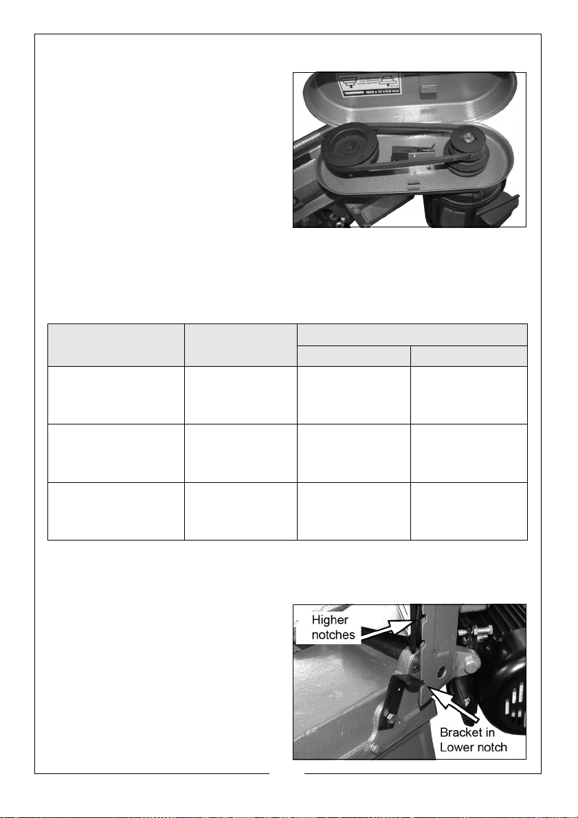
1. With the power disconnected,
loosen the drive belt adjusting bolt
in order to slacken the drive belt.
2. Open the drive guard and
change the position of the belt to
obtain the required speed.
3. Re-tension the belt so that it can
be deflected by approximately 1/2” in the centre of its span.
4. Lock the motor firmly in position.
5. Close the drive guard.
Material Speed (M/min) Belt Groove Used
Motor Pulley Driven Pulley
Stainless or
Alloy Steel
Bearing Bronzes
Mild Steel,
Hard Brass
or Bronze
Soft Brass,
Aluminium and
other light materials
20 Small Large
29 Medium Medium
50 Large Small
CHANGING THE BLADE
If the blade becomes worn or damaged it should be replaced as follows:
1. Disconnect the bandsaw from the
power supply.
2. Raise the arm to its vertical
position and lock in place by
setting the locking bracket in the
lower notch in the saw body.
3. Undo the thumbscrew securing
the blade safety cover and open
the cover.
16
Parts & Service: 020 8988 7400 / E-mail: [email protected] or [email protected]
Page 17
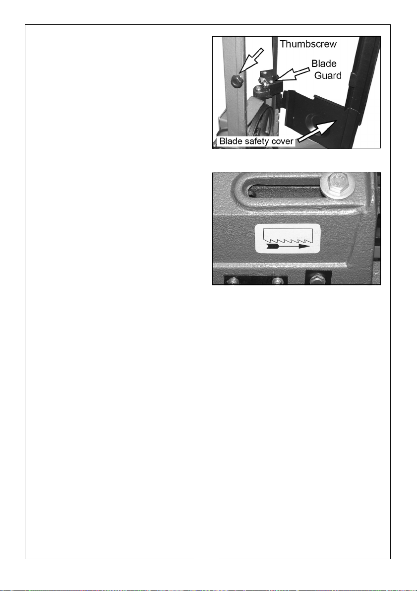
4. Remove the blade guard
attached to the blade guide
assembly.
5. Turn the blade tension adjuster
knob anticlockwise to slacken the
blade and allow removal from the
pulleys and from between the
guide bearings, paying due care
to the sharpness of the teeth.
6. Feed the new blade between the
blade guide bearings and over the top pulley.
• Note the direction of the saw
teeth in relation to the symbol
shown.
7. Hold the blade in position with
one hand whilst feeding it downwards and over the bottom
pulley.
8. Ease the blade onto the pulleys as
far as possible.
9. Tension the blade according to
the instructions on page 15.
10. Place 2-3 drops of oil on the blade.
11. Re-fit the blade guard and close the blade safety cover.
12. Observing all safety precautions, start the bandsaw and allow to run for a
few minutes at low speed in order to bed in the new blade.
13. Once the blade has been replaced it is recommended that the blade is
‘Run In’ for a few minutes before starting work.
NOTE: If the pulleys have not been interfered with, the blade should run
evenly, just off the lip on the back of each pulley. If it wanders off
the pulleys, or scuffs against the lip at the back of the pulley,
evident by a scraping sound, the tracking will need adjustment see below.
BLADE TRACKING ADJUSTMENT
Blade tracking is carried out at the factory and it should not normally require
re-adjustment. If the blade comes off the pulleys, first try a new blade, as this
should normally cure the problem. If the new blade does not track correctly,
adjust the tracking as follows:
17
Parts & Service: 020 8988 7400 / E-mail: [email protected] or [email protected]
Page 18
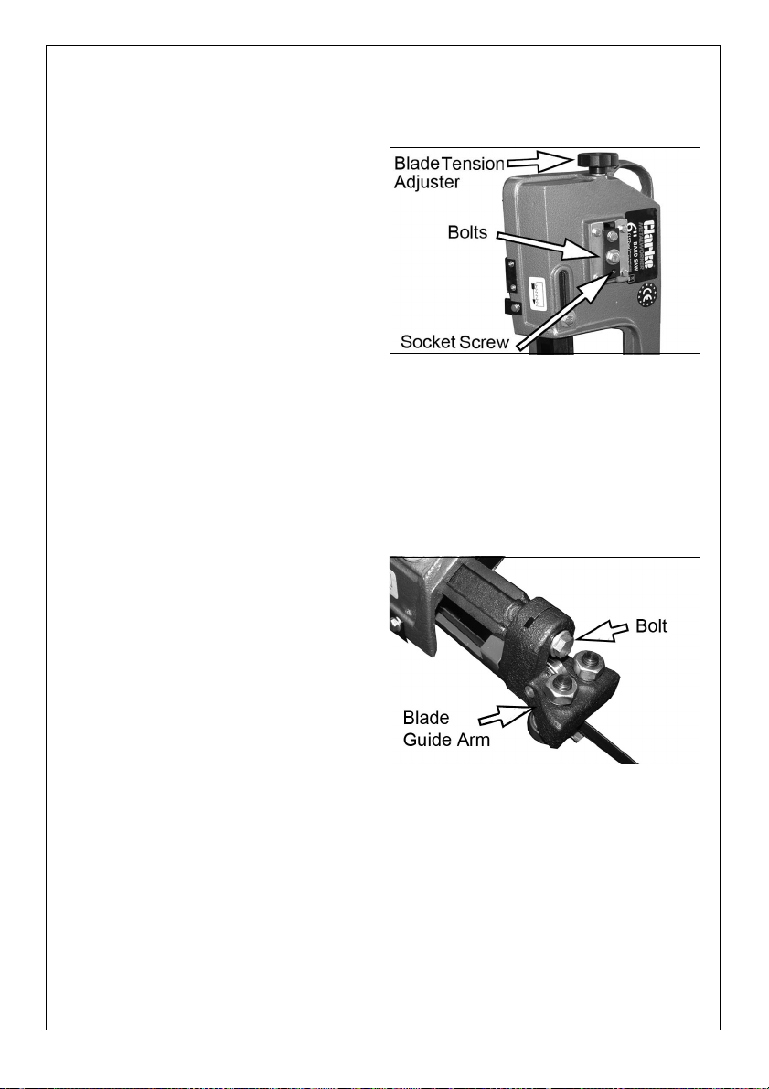
1. Disconnect from the power supply, set the saw arm is in the vertical
position.
2. Open the blade safety cover and adjust the blade to moderate tension.
3. Slacken the two bolts, shown by
one turn.
4. Turn the blade by hand, (taking
care of sharp teeth), making sure
that the blade runs closely against
the lip on the back edge of the
pulleys but without rubbing.
• If the blade tends to rub hard
against the lip on the back edge
of the pulleys, a scraping sound
will be heard. If this happens, the socket screw shown above should be
turned ANTICLOCKWISE until the blade runs evenly on the pulley. Should
the blade tend to run off the pulley, turn the socket screw CLOCKWISE.
5. Close the blade safety cover. Switch on the saw and test the action of the
blade to ensure it runs true.
6. If necessary, stop and carry out the adjustment again until satisfied.
ADJUSTING THE BLADE ANGLE
The blade must be at right angles (or
vertical) to the machine bed when
cutting horizontally. To achieve this:
1. Loosen the bolt shown.
2. Adjust the blade guide to make
the blade vertical to the bed.
3. Re-tighten the bolt.
4. Check the blade Is vertical by
placing a set-square on the bed.
It not, repeat the process 1 to 3.
18
Parts & Service: 020 8988 7400 / E-mail: [email protected] or [email protected]
Page 19
METHODS OF OPERATION
HORIZONTAL CUTTING
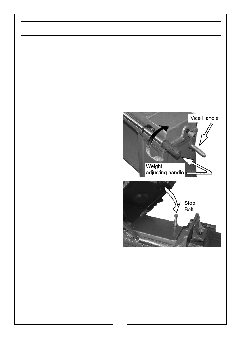
1. Raise the arm until held by the support bracket.
2. Open the vice by turning the handle at the end of the base anticlockwise.
3. Clamp the workpiece securely in the vice by turning the vice handle
clockwise. (If the workpiece is long it should be supported).
4. Switch on the bandsaw and slowly lower the saw onto the workpiece.
• Let the weight of the saw provide the cutting force.
5. Set the spring tension by turning
the weight adjusting handle to set
the cutting force of the saw.
• The saw automatically shuts off at
the end of the cut when the
switch cut-off tip on the arm
touches the OFF switch. This can
be prevented from happening by
increasing the length of the stop
bolt.
6. Adjust the stop bolt if required
and tighten the locking nut to
secure.
19
Parts & Service: 020 8988 7400 / E-mail: [email protected] or [email protected]
Page 20
VERTICAL CUTTING
To operate in the vertical cutting position, the table must be fitted and the saw
body locked in the vertical position.
LOCKING IN THE VERTICAL POSITION
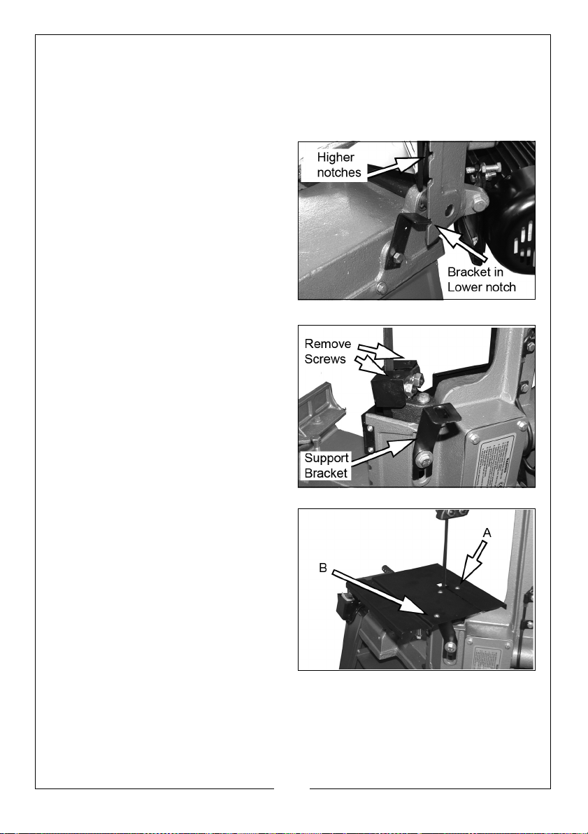
1. Rotate the vertical locking
bracket to an upright position,
and locate in the notch on the
saw body.
2. If you have difficulty in locating
this bracket in the notch, adjust
the bracket securing bolt until the
bracket locates;- then tighten the
bracket securing bolt.
FITTING THE TABLE
1. Remove the screws from the
blade guide.
2. Attach the table support bracket
to the bolt as shown, but leaving
the bolt slack.
3. Set the table on top of the guide
assembly and insert screws A into
the guard.
4. Fit screw B (with the nut and
washer), into the bracket and
tighten fully.
5. When cutting, adjust the upper
blade guide so that no more
blade is exposed than is required
to cut the workpiece.
6. Keep hands well clear of the blade and use a push stick for small
workpieces.
7. Switch off immediately when cutting is complete.
20
Parts & Service: 020 8988 7400 / E-mail: [email protected] or [email protected]
Page 21

TROUBLESHOOTING
Problem Check Solution
Excessive blade
breakage
Premature blade
dulling
Unusual wear on
side/back of
blade
Teeth ripping from
blade
1. Material loose in vice.
2. Incorrect speed or feed.
3. Blade pitch too great.
4. Material too hard.
5. Incorrect blade tension.
6. Teeth touching work before
start-up.
7. Blade rubs on wheel flange.
8. Mis-aligned guide bearings.
1. Teeth too coarse.
2. Speed too great.
3. Inadequate feed pressure.
4. Hard spots/scale on
material.
5. Work hardening of material.
6. Blade twist.
1. Blade guides worn.
2. Blade guide bearings not
adjusted correctly.
3. Blade guide bearing.
bracket loose.
1. Teeth too coarse for work.
2. Too slow speed.
3. Vibrating workpiece.
4. Teeth clogging.
1. Clamp work securely.
2. Adjust speed or feed.
3. Replace with finer.
toothed blade.
4. Select a slower speed
and finer toothed
blade.
5. Adjust blade tension.
6. Place blade in contact.
with work after motor
has started.
7. Adjust wheel alignment.
8. Adjust guide bearings.
1. Use finer tooth blade.
2. Reduce speed.
3. Reduce spring tension
on side of saw.
4. Reduce speed/increase
feed pressure.
5. Increase feed pressure
by reducing spring
tension.
6. Replace with a new
blade & adjust tension.
1. Replace guides.
2. Adjust bearings.
3.Tighten bracket.
1. Use finer tooth blade.
2. Reduce pressure
/ increase speed.
3. Clamp workpiece.
securely.
4. Use coarser blade or
brush away swarf.
21
Parts & Service: 020 8988 7400 / E-mail: [email protected] or [email protected]
Page 22
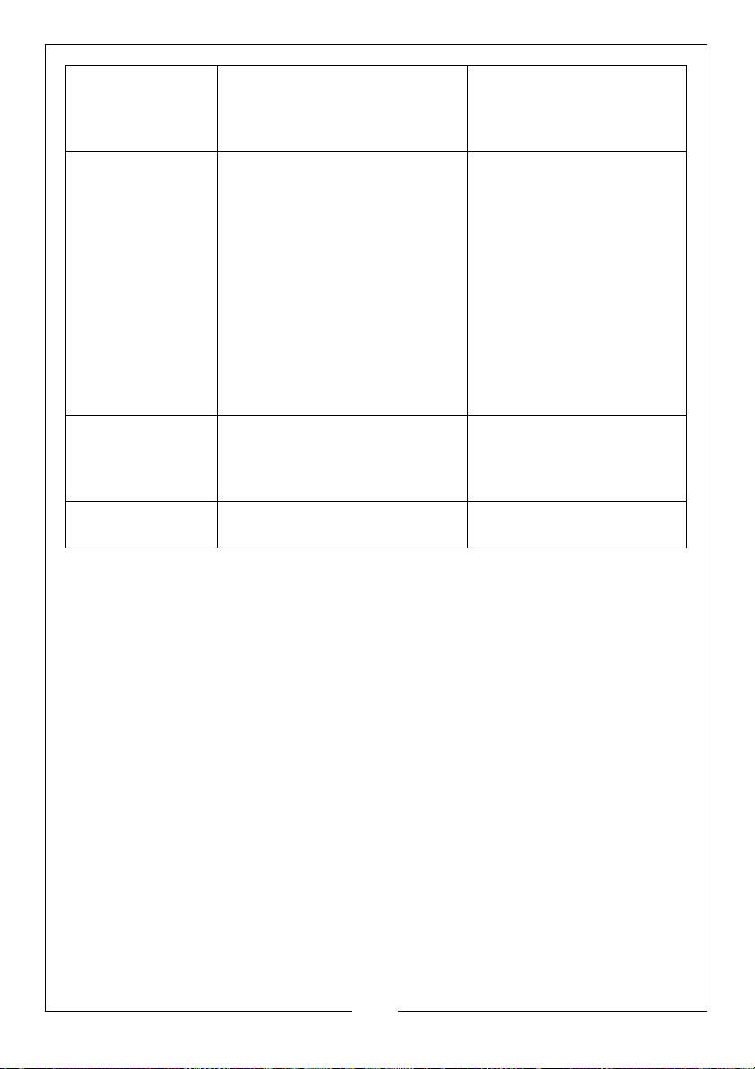
Motor running too
hot
1. Blade tension too high.
2. Drive belt too tight.
3. Gears need lubrication.
4. Blade is binding.
Bad cuts (not
1. Feed pressure too great.
cutting square)
2. Guide bearing not adjusted
properly.
3. Inadequate blade tension.
4. Dull blade.
5. Speed incorrect.
6. Blade guides too far apart.
7. Blade guide assembly loose
8. Blade tracks too far away
from wheel flanges.
Bad cuts (rough) 1. Too great a speed of feed.
2. Blade is too coarse.
3. Blade tension slack.
Blade is twisting 1. Blade is binding.
2. Too much blade tension.
1. Reduce blade tension.
2. Reduce belt tension.
3. Check oil bath.
4. Decrease feed speed.
1. Reduce pressure by
increasing spring tension
of the saw.
2. Adj guide bearing
clearance not greater
than 0.001”.
3. Increase blade tension.
4. Replace blade.
5. Adjust speed.
6. Adjust guides space.
7. Tighten.
8. Check and adjust blade
tracking.
1. Decrease speed of feed
2. Replace with finer
blade.
3. Adjust blade tension.
1. Decrease feed pressure
2. Decrease blade tension
22
Parts & Service: 020 8988 7400 / E-mail: [email protected] or [email protected]
Page 23
MAINTENANCE
WARNING: ALWAYS SWITCH OFF AND DISCONNECT FROM THE POWER
SUPPLY BEFORE CARRYING OUT ANY CLEANING OR MAINTENANCE
TASKS.
GENERAL
Remove all accumulated swarf from inside the bandsaw frequently using a
soft brush and/or vacuum cleaner. Alternatively, if compressed air is used,
ensure it is set to no more than 10 psi and wear protective safety glasses.
Maintain a thin film of oil on all unpainted surfaces including all screw threads
to protect your saw from corrosion.
• All bearings are lubricated for life and require no mainenance.
GEARBOX
The drive gears run in an oil bath and will not require a lubricant change more
often than once a year if in daily use.
To change the oil proceed as follows:
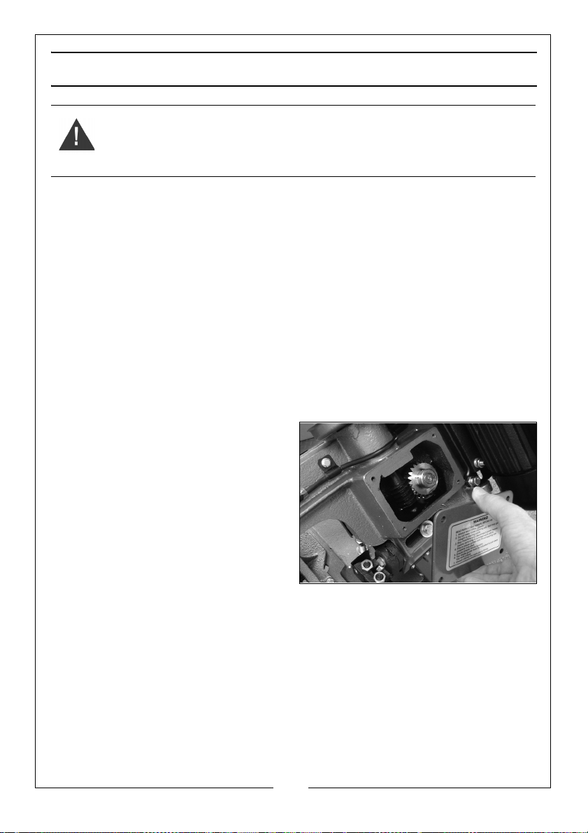
1. Lower the saw to a horizontal
position and remove the four bolts
securing the gearbox cover.
2. Remove the gearbox cover.
3. Place a container under the right
lower corner of the gear box and
slowly raise the bandsaw until the
oil drains into the container.
4. Lower the saw and wipe up any
excess oil and foreign matter with
a soft rag.
5. Replace the oil with a similar quantity until the drive gears are covered.
6. Replace the cover and gasket and tighten the four bolts.
STORAGE
When storing the bandsaw, disconnect the power cable, cover the machine
with a plastic sheet and store it in a dry location.
23
Parts & Service: 020 8988 7400 / E-mail: [email protected] or [email protected]
Page 24
PARTS LIST & DIAGRAM
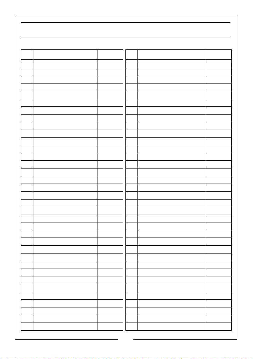
NO DESCRIPTION NO DESCRIPTION
1 Hexagon Headed Bolt SD450001 56 Hex Bolt SD45100
2 Nut SD45002 57 Adjusting Bracket SD45057
3 Washer SD45003 58 Thumb Screw SD45058
4 Floor Stand (R/H) SD45004 59 Blade Safety Cover SD45059
5 Micro-switch SD45180 60 Circlip SD45060
6 Split Pin SD45006 61 Bearing SD45061
7 Stand Shelf SD45007 62 Guide Bearing Spindle SD45062
8 Micro-Switch Holder SD45008 63 Bearing Shaft Pin SD45063
9 Wheel SD45005 64 Blade Adjustable Seat SD45064
10 Switch Bolt SD45009 65 Adjustable Bracket SD45065
11 Hexagon Headed Bolt SD45011 66 Bolt SD45066
12 Nut SD45012 67 Spring Washer SD45067
13 Floor Stand (L/H) SD45013 68 Screw SD45068
14 Floor Stand Handle SD45014 69 Blade Guide Block SD45069
15 Adjusting Rod SD45015 70 Nut SD45070
16 Power Cable & Plug SD45016 71 Blade Wheel - Front SD45071
17 Pivot Pin SD45017 72 Blade Wheel Bearing Cover SD45072
18 Support Angle Bracket SD45018 73 Key SD45073
19 Stock Stop SD45019 74 Grub Screw SD45074
20 Bolt SD45020 75 Hex Headed Bolt SD450171
21 Stock Stop Rod SD45021 76 Switch Cut-off Tip SD45076
22 Wire Relief Retainer SD45022 77 Blade Wheel - Rear SD45077
23 No-Volt Switch SD45023 78 Nut SD45078
24 Washer SD45024 79 Tension Adjustment Knob SD45079
25 Handle Grip SD45025 80 Saw Blade SD45113
26 Blade Guard SD45026 81 Body Frame SD45081
27 Washer SD45027 82 Capacitor Cover SD45082
28 Vice Crank Handle SD45028 83 Hex Head Bolt SD45083
29 Blade Guard (L/H) SD45029 84 Motor Mounting Plate SD45084
30 n/a n/a 85 Motor SD45085
31 Thrust Washer SD45030 86 Motor Pulley SD45086
32 Vice Lead Screw SD45032 87 Ball Bearing SD45087
33 Vice Control Block SD45033 88 Bearing Bushing SD45088
34 Moving Vice Plate SD45034 89 Oil Seal SD45089
35 Washer SD45035 90 Transmission Wheel Shaft SD45090
24
Parts & Service: 020 8988 7400 / E-mail: [email protected] or [email protected]
Page 25
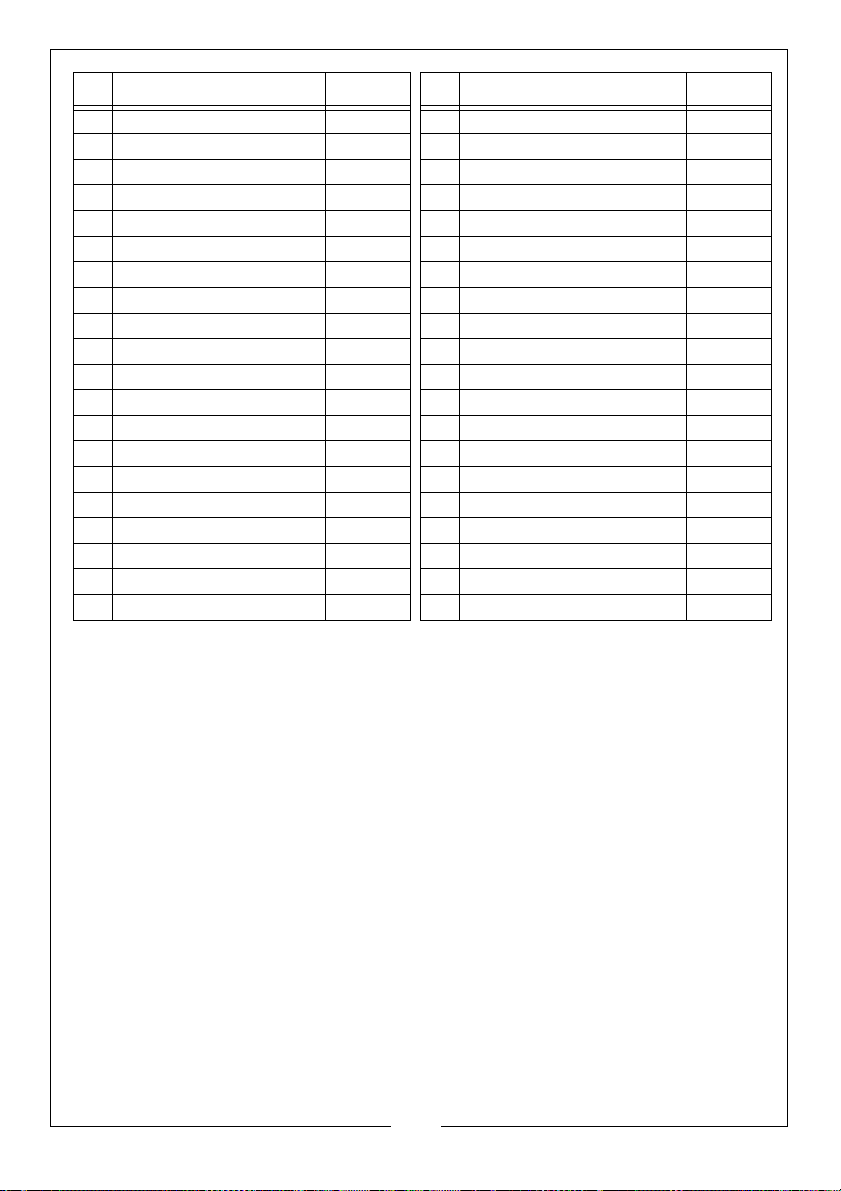
NO DESCRIPTION NO DESCRIPTION
36 Hex headed Bolt SD45036 91 Transmission Gear SD45091
37 Machine Bed SD45037 92 Gearbox Gasket SD45092
38 Circlip SD45040 93 Gearbox Cover SD45093
39 Scale SD45038 94 Worm Gear Shaft SD45094
40 Condenser 100uf mk06005 95 Drive Belt Z545 SD45112
41 Hexagon Headed Bolt SD45083 96 Bearing Bushing SD45096
42 Nut SD45012 97 Guide Block SD45103
43 Drive Guard SD45110 98 Driven Spindle SD45126
44 Connecting cable SD45044 99 Circlip SD45080
45 Bracket SD45045 100 Slide Plate SD45073
46 Spring Adjusting Screw SD45046 101 Closing Plate SD45101
47 Spring SD45047 102 Support Bracket SD45056
48 Screw SD45048 103 Axle Bracket SD45174
49 Mitering Vice Plate SD45049 104 Washer SD45173
50 Hexagon Headed Bolt SD45050 105 Axle SD45176
51 Pulley SD45051 106 Split Pin SD45175
52 Hexagon Headed Bolt SD45052 107 Machine Screw SD45167
53 Stop Bolt SD45053 108 Nut SD45172
54 Pivot Arm SD45054 109 Washer SD45109
55 Vertical Cutting Plate SD45055
When requesting replacement parts pleaase quote: SD45001 - 109.
Replacement Blades and sundries are available from your Clarke dealer;
Blade (14tpi) 1 per pack Part no 65009695
Blade (24tpi) 1 per pack Part no 65021135
Replacement drive belts Part no 2100112
Clarke cutting oil ref: 1 Litre Part no 3051059
Clarke cutting oil ref: 5 Litre Part no 3051061
25
Parts & Service: 020 8988 7400 / E-mail: [email protected] or [email protected]
Page 26
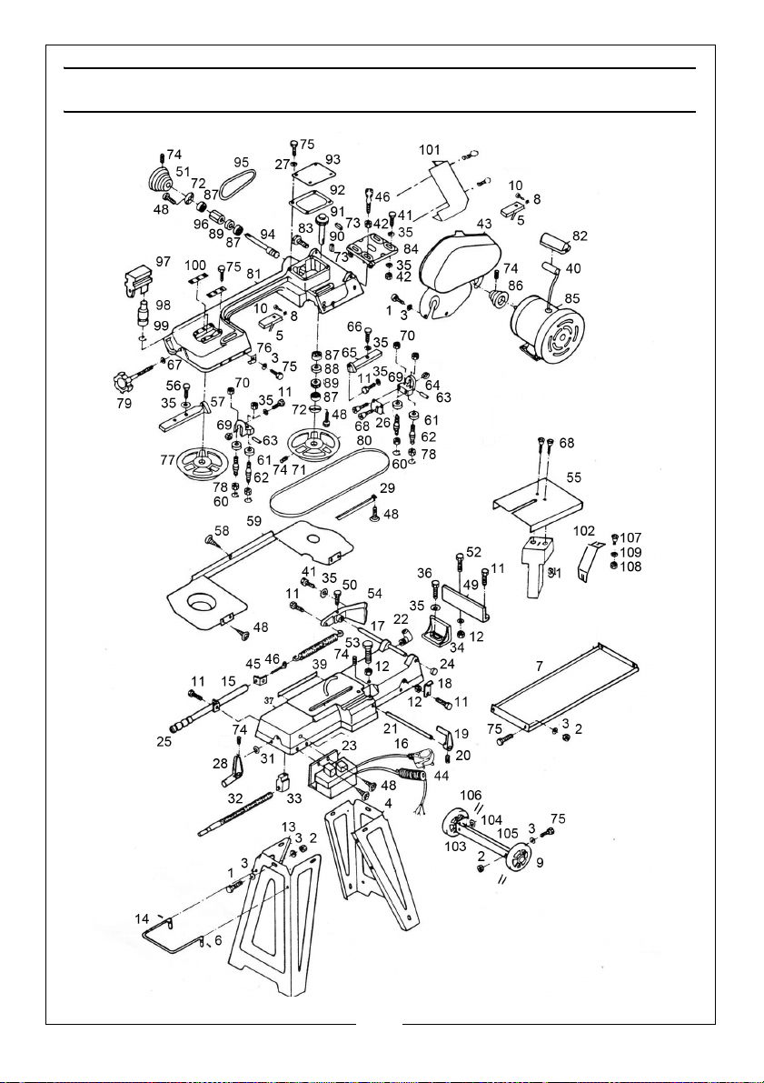
PARTS LIST & DIAGRAM
26
Parts & Service: 020 8988 7400 / E-mail: [email protected] or [email protected]
Page 27

DECLARATION OF CONFORMITY
27
Parts & Service: 020 8988 7400 / E-mail: [email protected] or [email protected]
Page 28

 Loading...