

Page 1
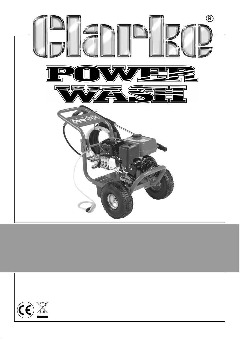
PETROL POWER WASHER
MODEL NO: PLS190N, PLS260N
PART NO: 7330345, 7330355
OPERATION & MAINTENANCE
INSTRUCTIONS
LS0314
Page 2
INTRODUCTION
Thank you for purchasing this CLARKE Petrol Power Washer.
Before attempting to use this product, please read this manual thoroughly and
follow the instructions carefully. In doing so you will ensure the safety of yourself
and that of others around you, and you can look forward to your purchase
giving you long and satisfactory service.
GUARANTEE
This product is guaranteed against faulty manufacture for a period of 12
months from the date of purchase. Please keep your receipt which will be
required as proof of purchase.
This guarantee is invalid if the product is found to have been abused or
tampered with in any way, or not used for the purpose for which it was
intended.
Faulty goods should be returned to their place of purchase, no product can
be returned to us without prior permission.
This guarantee does not effect your statutory rights.
UNPACKING
Unpack your power washer and check to ensure the following items are
present. Contact your Clarke dealer immediately if any parts are missing or
damaged.
Power Washer Delivery Hose
Gun Assembly Lance / Nozzle Assembly
2 x Wheels 2 x Rubber Foot
Inlet Hose Detergent Hose
2 x Axle Tommy Bar
Hose / Lance Storage Bracket Spark Plug Box Spanner
Pump Vent Assembly Separate engine manual
2
Parts & Service: 020 8988 7400 / E-mail: [email protected] or [email protected]
Page 3

TABLE OF CONTENTS
INTRODUCTION . . . . . . . . . . . . . . . . . . . . . . . . . . . . . . . . 2
GUARANTEE. . . . . . . . . . . . . . . . . . . . . . . . . . . . . . . . . . . 2
UNPACKING . . . . . . . . . . . . . . . . . . . . . . . . . . . . . . . . . . 2
TABLE OF CONTENTS . . . . . . . . . . . . . . . . . . . . . . . . . . . . 3
GENERAL SAFETY RULES . . . . . . . . . . . . . . . . . . . . . . . . . 4
SAFETY SYMBOLS. . . . . . . . . . . . . . . . . . . . . . . . . . . . . . . 5
OVERVIEW . . . . . . . . . . . . . . . . . . . . . . . . . . . . . . . . . . . . 6
ASSEMBLY . . . . . . . . . . . . . . . . . . . . . . . . . . . . . . . . . . . . 7
BEFORE USE . . . . . . . . . . . . . . . . . . . . . . . . . . . . . . . . . . . 9
USING YOUR POWER WASHER . . . . . . . . . . . . . . . . . . . . 12
MAINTENANCE . . . . . . . . . . . . . . . . . . . . . . . . . . . . . . . . 16
STORAGE . . . . . . . . . . . . . . . . . . . . . . . . . . . . . . . . . . . . . 18
ENVIRONMENTAL RECYCLING POLICY . . . . . . . . . . . . . 18
TROUBLESHOOTING. . . . . . . . . . . . . . . . . . . . . . . . . . . . . 19
SPECIFICATIONS . . . . . . . . . . . . . . . . . . . . . . . . . . . . . . . 21
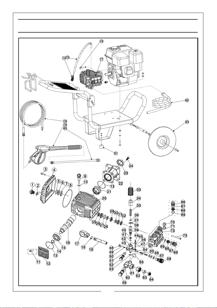
EXPLODED DIAGRAM . . . . . . . . . . . . . . . . . . . . . . . . . . . 22
PARTS LIST PLS190N . . . . . . . . . . . . . . . . . . . . . . . . . . . . . 23
PARTS LIST PLS260N . . . . . . . . . . . . . . . . . . . . . . . . . . . . . 24
PLS190N DECLARATION OF CONFORMITY . . . . . . . . . . 25
PLS260N DECLARATION OF CONFORMITY . . . . . . . . . . 26
NOTES . . . . . . . . . . . . . . . . . . . . . . . . . . . . . . . . . . . . . . . 27
3
Parts & Service: 020 8988 7400 / E-mail: [email protected] or [email protected]
Page 4
GENERAL SAFETY RULES
WARNING: Water at high pressure can be dangerous and can cause
damage to persons or property if the operator is careless. Never allow
anyone to operate this equipment unless they are thoroughly reliable,
and familiar with the safety precautions.
1. NEVER direct the spray towards any person or animal.
2. NEVER direct the spray towards electrical wiring or equipment.
3. NEVER hold your finger over the high pressure nozzle.
4. NEVER allow children to use this machine.
5. NEVER operate the machine with any of the covers removed.
6. NEVER attempt any repairs to this machine always refer to a qualified
service agent.
7. NEVER supply any liquid other than water to the water inlet.
8. NEVER use the chemical injection facility to introduce solvents, e.g. paint
thinners, petrol, oil etc.
9. ALWAYS release any residual pressure in the system by turning off the water
supply and operating the trigger before disconnecting any hose or
accessory.
10. ALWAYS keep the machine itself dry and well clear of water spray
11. ALWAYS wear protective clothing and safety glasses. Loose particles and
other debris may be propelled at high speed by the water jet.
12. ALWAYS grip the gun firmly before pressing the trigger, expect the gun to
‘kick’ when starting.
13. ALWAYS respect the requirements of the local water company. Power
washers may only be connected to the mains drinking water supply, if a
backflow preventer valve is installed in the supply hose.
14. When not in use, ALWAYS disconnect from the water supply, and ensure the
system is completely drained. Store in a cool dry location.
15. When using the chemical injection facility, use only the chemical cleaning
agents (detergents), that are approved for power washers. CLARKE Traffic
Film Remover or CLARKE Wash and WAX (available from your dealer), is
recommended.
16. Refuel in a well ventilated area with the engine switched off.
17. Do not use or refuel near naked flames.
4
Parts & Service: 020 8988 7400 / E-mail: [email protected] or [email protected]
Page 5
SAFETY SYMBOLS
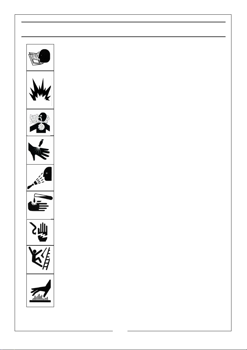
ALWAYS: Read t his ma nual. U nders tand all warnings and
instructions before operating this equipment.
DANGER: Risk of fire or explosion. Shut off engine before
adding fuel. Keep work area free of combustible materials.
Do not spray flammable liquids.
DANGER: Risk to breathing. Engine exhaust fumes can kill.
Fo r out door use only. Work in a well ventilated area.
WARNING: Risk of injection or severe injury. Do not direct
discharge stream at persons or animals. Keep clear of nozzle.
This machine is to be used only by qualified operators.
WARNING: Risk of spray injury. Spray can propel objects.
Always wear ANSI approved Z87.1 Safety Glasses.
WARNING: Risk of chemical burn. Never spray acids, corrosive
or to xic chemicals. Use only cleaners formulated for power
washers.
WARNING: Risk of electrocution. Never direct spray toward
any electrical device or electrical outlet.
WARNING: Risk of unsafe operation. Keep children away
from this equipment. Gun kicks back. Hold with both hands.
WARNING: Risk of hot surfaces. Avoid contact with hot
engine exhaust components. Don't allow hoses to contact
the engine muffler during or after use.
5
Parts & Service: 020 8988 7400 / E-mail: [email protected] or [email protected]
Page 6
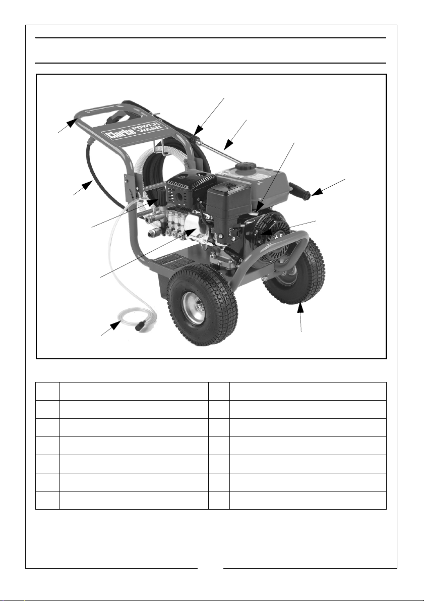
OVERVIEW
1
2
10
4
5
6
7
8
9
3
11
NO DESCRIPTION NO DESCRIPTION
1 Gun/lance 7 High pressure hose
2 Spray wand 8 Foldable handle
3 Engine 9 Pressure regulator
4 Adjustable nozzle 10 Engine starter
5 Wheels 11 Throttle
6 Chemical detergent hose
6
Parts & Service: 020 8988 7400 / E-mail: [email protected] or [email protected]
Page 7
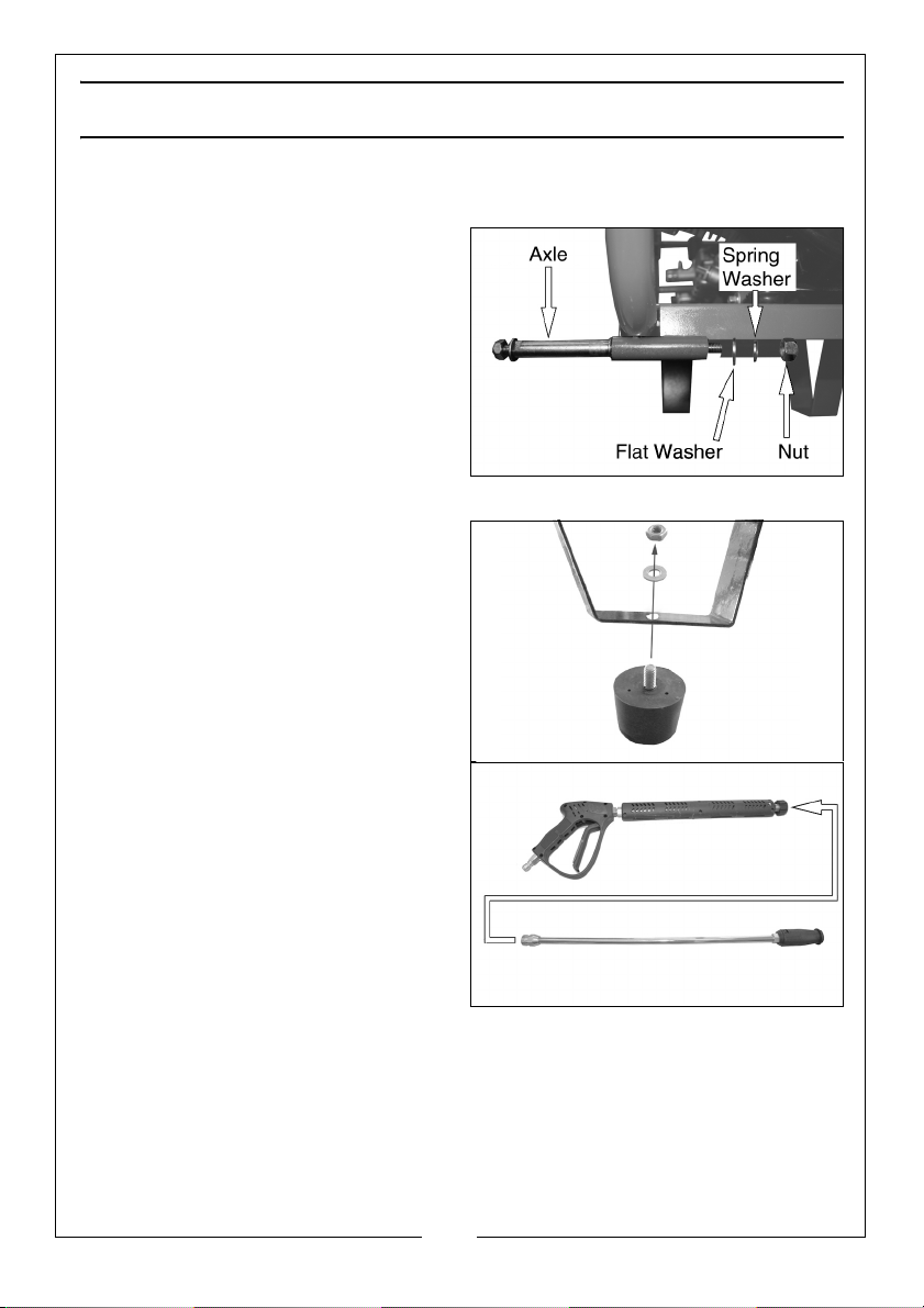
ASSEMBLY
CONNECTING THE WHEELS
1. Remove the nut, spring washer
and washer from the axle.
2. Fit the axles into the axle ports as
shown, secure with the nut, spring
washer and flat washer.
3. Fit the wheels to the axles and
secure with the nut and washer.
NOTE: Do not overtighten the nuts,
the wheels must be able to
rotate freely.
RUBBER FEET
1. Fit the rubber feet to the legs as
shown.
ASSEMBLE THE LANCE
1. Connect the spray wand to the
lance and tighten securely.
7
Parts & Service: 020 8988 7400 / E-mail: [email protected] or [email protected]
Page 8
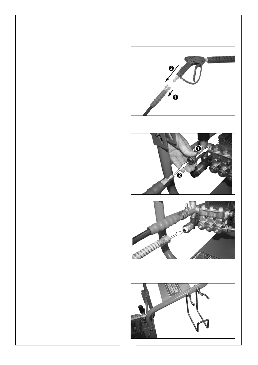
THE HIGH PRESSURE HOSE
CONNECT THE HOSE TO THE GUN
1.
Slide the connector on the hose
backwards.
2. Push the gun into the connector.
3. Release the connector.
NOTE: Mak
CONNECT THE HOSE TO THE POWER WASHER
Slide the connector on the power
1.
washer towards the machine.
2. Push the hose into the connector.
3. Release the connector.
NOTE: Mak
e sure the connection is
secure.
e sure the connection is
secure.
CONNECT WATER INLET HOSE
1. Remove the travel cap if fitted.
2. Connect the water supply hose to
the water
NOTE: Water source must provide
NOTE: Make sure the water inlet
inlet.
a minimum of 5 gallons per
minute at 20 p.s.i.
hose is screwed on tightly.
HOSE / LANCE STORAGE BRACKET
1. Fit the bracket into the position
shown and secure using the
washers and nuts supplied
8
Parts & Service: 020 8988 7400 / E-mail: [email protected] or [email protected]
Page 9
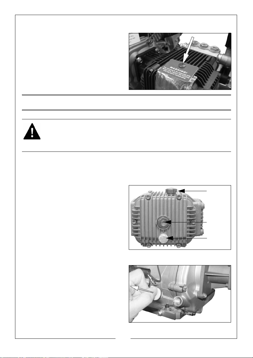
REMOVE THE TRAVEL PLUG BEFORE USE.
SIGHT GLASS
DRAIN CAP
OIL FILLER CAP
1. Remove the red travel plug.
2. Inside the small bag attached is
an oil
filler cap which needs to be
fitted in its place.
BEFORE USE
WARNING: TO CARRY OUT THIS CHECK, PLACE THE POWER WASHER ON
LEVEL GROUND WITH THE ENGINE SWITCHED OFF.
WARNING: TAKE CARE NOT TO TOUCH ANY HOT PARTS OF THE POWER
WASHER WHEN CHECKING THE OIL LEVELS.
IMPORTANT: The engine is supplied without any oil in it and must be filled to
the correct level before use, see below.
CHECKING THE PUMP OIL LEVEL
Look at the sight glass on the pump
to check the oil level inside.
If required, remove the oil filler cap
and top up with oil.
• We recommend the use of
SAE30 oil in this pump.
CHECKING THE ENGINE OIL LEVEL
1. Turn the oil filler cap/dipstick anticlockwise and remove it from the
oil filler tube, wipe the dipstick
with a clean cloth.
2. Insert the oil filler cap/dipstick
back into the oil filler tube and
then remove it again. Do not
screw it in when doing this.
Parts & Service: 020 8988 7400 / E-mail: [email protected] or [email protected]
9
Page 10
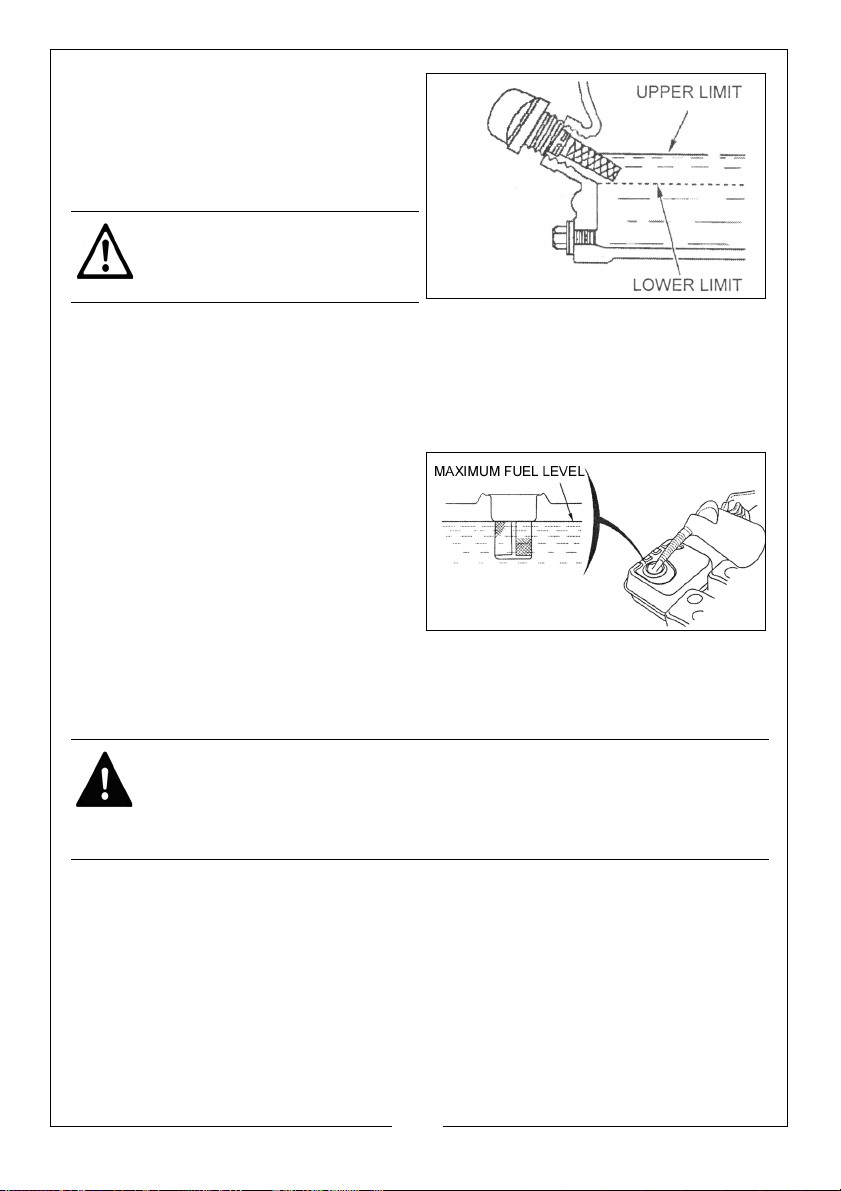
3. If the oil is low, fill the oil reservoir to
the edge of the oil filler hole.
• We recommend the use of
SAE30 oil in
4. Replace the oil filler cap.
CAUTION: RUNNING THE
ENGINE WITH INSUFFICIENT OIL
CAN CAUSE ENGINE DAMAGE.
the engine.
CHECKING THE FUEL LEVEL
1. To check the fuel level, remove the fuel tank cap.
2. Just inside the fuel tank is a fuel strainer
remove any contaminants which may have accumulated.
3. Refuel in a well-ventilated area,
before starting the engine. If the
engine has been running, allow it
to cool. Refuel carefully to avoid
spilling fuel. Do not fill above the
fuel strainer shoulder.
4. After refueling, Replace the fuel
filler cap securely.
. Check this filter periodically and
RECOMMENDED FUEL
Use unleaded petrol with an octane rating of 86 or higher. Do not overfill.
WARNING: ALWAYS REFUEL IN A WELL VENTILATED AREA AWAY FROM
ANY HEAT SOURCES.
WARNING: ALLOW THE UNIT TO COOL DOWN BEFORE REFUELLING.
WARNING: DO NOT LEAVE FUEL WITHIN THE REACH OF CHILDREN.
10
Parts & Service: 020 8988 7400 / E-mail: [email protected] or [email protected]
Page 11
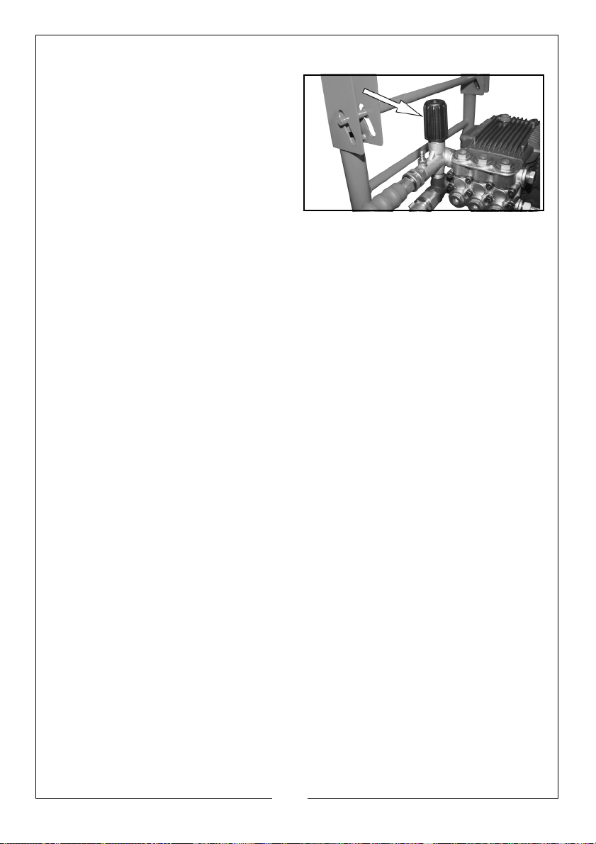
PRESSURE REGULATOR
When supplied, the pressure
regulator may be set to minimum.
Turn the pressure regulator on the
pump fully clockwise to allow water
pressure to build up when the
pressure washer is running.
If you find the pressure is too high, you
can adjust this later.
11
Parts & Service: 020 8988 7400 / E-mail: [email protected] or [email protected]
Page 12
USING YOUR POWER WASHER
POWER WASHER TERMINOLOGY
PSI: Pounds per square inch, the unit of measurement for water pressure.
GPM: Gallons per minute.
CU: Cleaning units, GPM x PSI.
Bypass mode: In bypass mode, the pump recirculates the water because the
trigger of the spray gun is not being pulled. If unit is left in bypass mode for
more than two minutes, the water temperature will rise to a dangerous level
and could damage internal components of the pump.
NOTE: Any damage to the pump due to these causes will not be
covered under warranty.
Thermal Relief Valve: In an effort to prevent extreme damage, pumps are
equipped with a thermal relief valve. This valve will open when the
temperature inside the pump becomes too high. This valve will then release a
gush of water in an effort to lower the temperature inside the pump.
Immediately after this occurs, the valve will close.
Chemical Injection System: This mixes cleaners or cleaning solvents with the
pressurised water to improve cleaning effectiveness.
12
Parts & Service: 020 8988 7400 / E-mail: [email protected] or [email protected]
Page 13
STARTING THE POWER WASHER
Prior to starting, refer to your engine manual for proper starting procedures for
your engine type.
1. Make sure the engine has sufficient fuel. See page 10.
2. Check engine oil level. See page 9.
3. Turn water supply on.
WARNING: FAILURE TO TURN ON THE WATER COULD CAUSE DAMAGE TO
THE PUMP.
4. Start the engine. See Engine Owners Manual for correct procedure.
NOTE: If the engine does not start after two pulls, pull the trigger on the
gun to relieve the pressure.
5. Pull the trigger on the gun to start water flow.
• Stand on a stable surface and grip gun/spray wand firmly with both
hands.
• Expect the gun to kick when the trigger is pulled.
6. Release trigger to stop water flow.
NOTE: The power washer will automatically go into bypass mode, in
bypass mode, the pump recirculates the water because the
trigger of the spray gun is not being pulled. If unit is left in bypass
mode for more than two minutes, the water temperature will rise
to a dangerous level and could damage internal components of
the pump.
WARNING: DO NOT ALLOW UNIT TO OPERATE IN BYPASS MODE FOR
MORE THAN TWO MINUTES AT ANY TIME.
13
Parts & Service: 020 8988 7400 / E-mail: [email protected] or [email protected]
Page 14
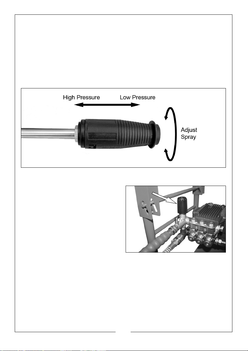
ADJUSTING THE SPRAY
The nozzle is adjustable to allow you to change the spray from a narrow jet of
water to a wide spray.
To adjust the nozzle, proceed as follows.
1. Hold the shaft of the lance in one hand.
2. Twist the nozzle with the other hand.
3. To vary the spray between narrow and wide, turn the nozzle counterclockwise
through a half-of-a-turn.
ADJUSTING THE PRESSURE
1. Adjust the pressure regulator on
the pump. Turn the pressure
regulator
to lower pressure. Once you have
finished using your power washer,
return the pressure regulator to its
original position.
2. Back away from the surface to be
cleaned. The further away you
are the less the pressure will be on
the surface being cleaned.
3. Reduce the speed of the engine (RPM). Slow the engine down and the
water pressure will also go down.
4. Adjust the spray to a wider angle.
5. Slide the nozzle forward for low pressure
knob counter clockwise
and backwards for high pressure.
14
Parts & Service: 020 8988 7400 / E-mail: [email protected] or [email protected]
Page 15
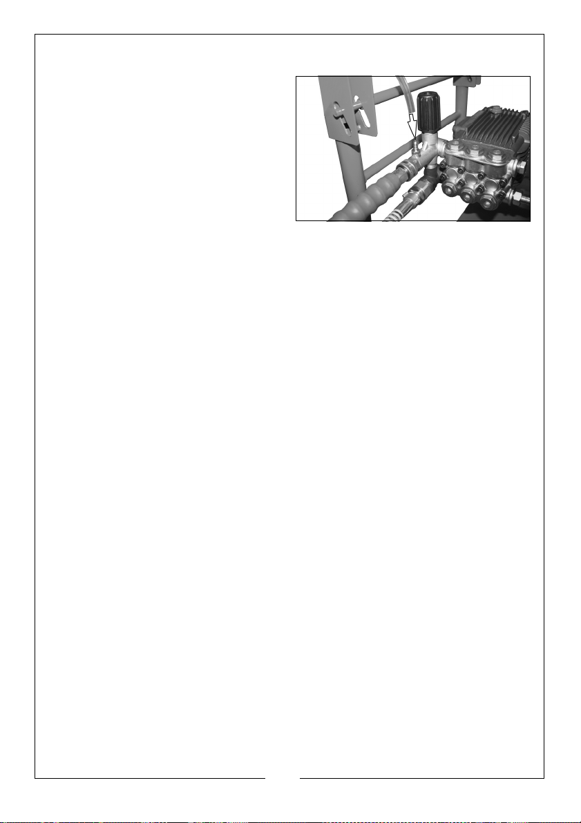
APPLYING CHEMICALS AND CLEANING SOLVENTS
1. Push the chemical hose onto the
ridged fitting as shown.
2. Place the other end of the
chemical hose with the filter on it,
into a container holding the
chemical/cleaning solution.
3. Slide the nozzle forward for low
pressure operation.
• The water/chemical ratio is
typically
chemical/ cleaning solution will be used.
7:1, for every 7 gallons of water pumped 1 gallon of
SHUTTING DOWN
1. After each use, if you have applied chemicals, place the chemical hose
into a container of clean water and run clean water through the chemical
injection system to flush the system thoroughly.
NOTE: Failure to do so could cause damage to the pump.
2. Turn the engine off. See engine owner's manual.
NOTE: NEVER
3. Turn the water supply off.
4. Pull the trigger on the spray gun to relieve any
5. See storage section in this manual for proper storage procedures.
turn the water off with the engine running.
water pressure.
15
Parts & Service: 020 8988 7400 / E-mail: [email protected] or [email protected]
Page 16
MAINTENANCE
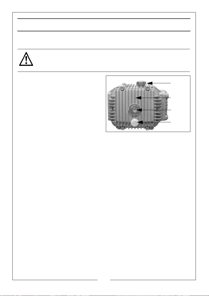
CRANKCASE
DRAIN PLUG
OIL FILLER CAP
SIGHT GLASS
CHANGING THE PUMP OIL
CAUTION: PROLONGED EXPOSURE TO USED OIL IS DANGEROUS,
ALWAYS WASH YOUR HANDS THOROUGHLY AFTER HANDLING USED OIL.
1.
Unscrew and remove the oil filler
cap.
2. Place an oil collection tray (not
supplied) under the drain plug.
3. Unscrew the drain plug, and allow
the
used oil to drain from the
crankcase into the oil collection
tray.
NOTE: Drain the oil when the engine
is warm, this will ensure the oil
flows out quicker.
4. Replace the drain plug and its ring seal.
5. With the power washer in a level position,
sight glass with the recommended oil.
6. Replace the oil filler cap.
fill to the centre of the
ENVIRONMENTAL PROTECTION
One of the most damaging sources of pollution is oil. Do not throw away used
oil with your domestic rubbish or down drains and sinks. Place it in a leak proof
container and take it to you local waste disposal site.
16
Parts & Service: 020 8988 7400 / E-mail: [email protected] or [email protected]
Page 17
CLEANING THE NOZZLE
if the nozzle becomes partially clogged or restricted by dirt or other foreign
material, excess pump pressure may develop. Clean the nozzle immediately by
following the instructions below.
1. Shut off the power washer and turn off the water supply.
2. Pull the trigger on the gun handle to relieve any water pressure.
3. Disconnect the spray wand from the gun.
4. Remove any obstructions and back flush with clean water.
5. Direct the water supply into the spray wand end for 30 seconds to back
flush loosened particles.
6. Reconnect the spray wand to the gun and turn on the water supply.
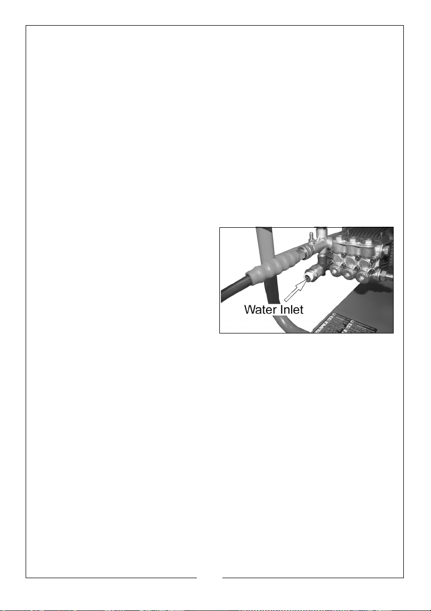
CLEANING THE WATER INLET
This water inlet should be checked
periodically and cleaned if
necessary.
17
Parts & Service: 020 8988 7400 / E-mail: [email protected] or [email protected]
Page 18
STORAGE
ENGINE
See the separate engine manual supplied for information regarding the storage
procedure.
PUMP
1. Drain all water from the high pressure hose, coil it and store it on the gun/
hose holder located on the side of the power washer handle.
2. Drain all water from the spray gun and spray wand by holding the gun/
wand vertically with the nozzle pointing down and pulling the trigger. Store
in the gun/hose holder.
3. Store all other parts so that they are protected from damage.
STORAGE PROCEDURE
For long term storage, the petrol tank should be drained. Ensure that the
engine is cold before draining the tank. Remove the fuel tank cap and use a
pump type syphon to drain the petrol into an appropriate, clean container.
Do not store petrol for long periods of time.
Dispose of excess petrol in an environmentally safe way. Your local recycling
centre can advise you on the best method of disposal. After the petrol tank
has been drained, start the engine and allow it to use any petrol that may
remain in the engine or fuel pipe. Make sure that the power washer has been
thoroughly cleaned before storing it in a clean dry place.
ENVIRONMENTAL RECYCLING POLICY
Through purchase of this product, the customer is taking on the
obligation to deal with the WEEE in accordance with the WEEE
regulations in relation to the treatment, recycling & recovery and
environmentally sound disposal of the WEEE.
In effect, this means that this product must not be disposed of with general
household waste. It must be disposed of according to the laws governing
Waste Electrical and Electronic Equipment (WEEE) at a recognised disposal
facility.
18
Parts & Service: 020 8988 7400 / E-mail: [email protected] or [email protected]
Page 19
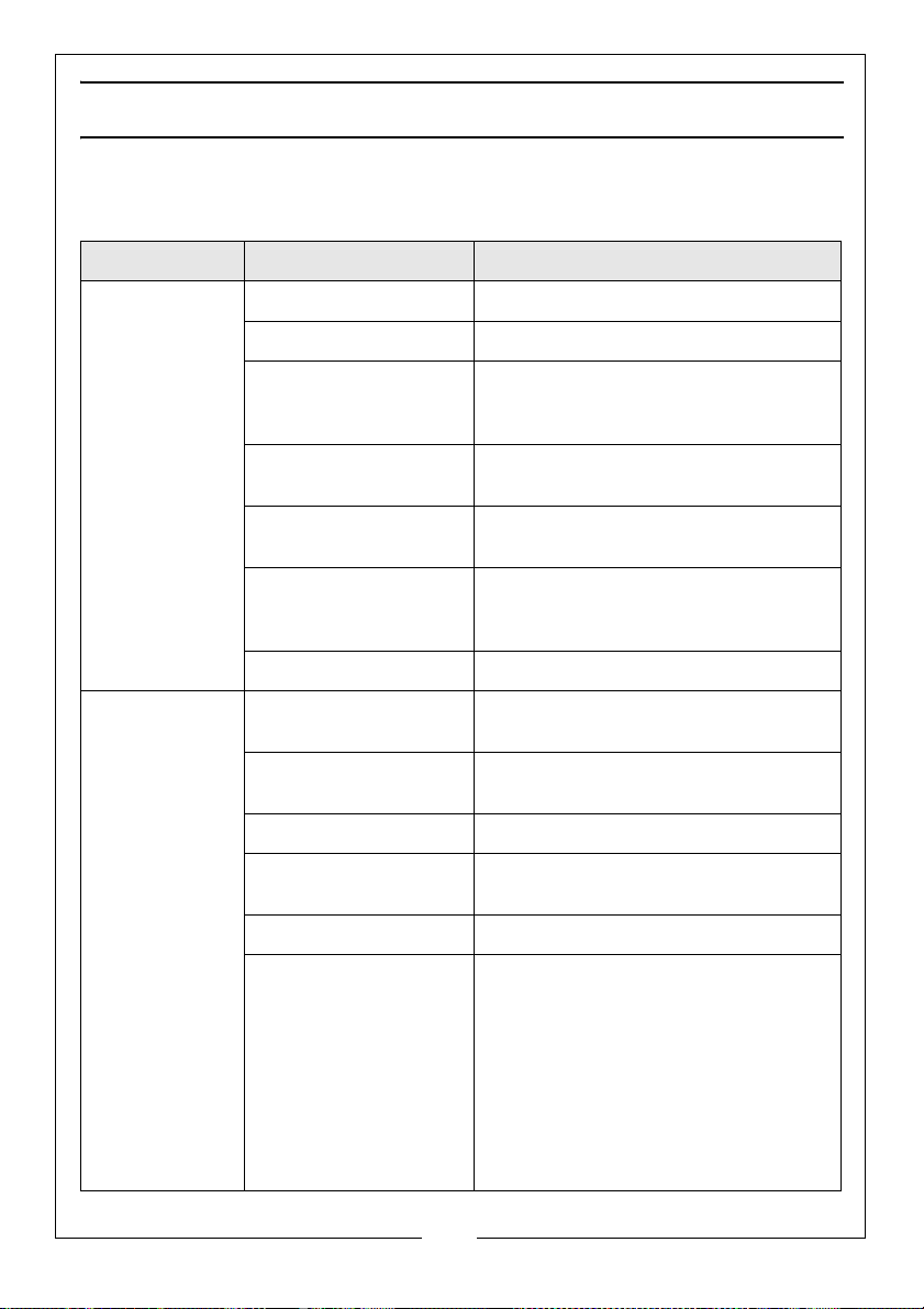
TROUBLESHOOTING
If the following does not solve your problem, please contact the CLARKE service
department.
PROBLEM CAUSE SOLUTION
Engine will not
start (see engine
manual for
further engine
troubleshooting)
Lack of pressure
(initial use)
No fuel Add fuel
Low oil Add oil
Pressure builds up after
two pulls on the recoil
starter or after initial use
Spark plug wire not
attached correctly
Engine switch is in the
OFF position
Choke lever is set to the
choke position when the
engine is warm
Fuel valve closed Open the fuel valve
Water supply is not
adequate
Leak in the high pressure
hose fitting
Nozzle is obstructed Clear the nozzle
Water filter screen is
clogged
Defective E-Z start valve Have it replaced by your dealer
Squeeze the gun trigger to relieve the
pressure
Attach the spark plug wire
Set the engine switch to the ON position
Set the choke lever to the NO CHOKE
position
Make sure your water supply can deliver 5
gallons per minute at 20psi
Tighten the fitting, use sealant tape if
required
Remove and clean the filter
Air in the supply hose Turn off the engine
Turn off the water supply,
Disconnect the water supply from the
pump inlet and turn on the water to expel
the air from the hose.
When all the air has been removed, turn
off the water supply and reconnect the
hose.
Turn on the water supply and pull the
trigger to expel any air in the gun/wand
19
Parts & Service: 020 8988 7400 / E-mail: [email protected] or [email protected]
Page 20
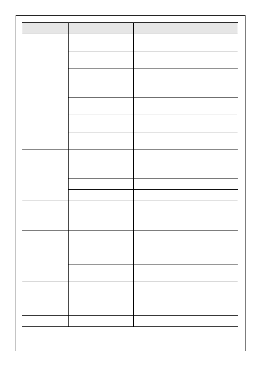
PROBLEM CAUSE SOLUTION
No or low
pressure (initial
use) continued
Will not draw
chemicals
No or low
pressure (after a
period of normal
use)
Water leaking at
the gun / spray
wand
connection
Choke lever is in the
CHOKE position
Throttle control lever is
not in the fast position
High pressure hose is too
long
Chemical filter is blocked Clean the filter
Chemicals being used
are too thick
High pressure hose is too
long.
Chemical build up inside
the chemical injector
Worn seal or packing Have it replaced by your dealer
Worn or obstructed
valves
Worn unloader piston Have it replaced by your dealer
Worn E-Z start valve Have it replaced by your dealer
Worn or broken O-ring Check and replace
Loose hose connection Tighten
Move the choke lever to the NO CHOKE
position
Move the throttle control lever to the fast
position
Make sure the high pressure hose is under
100 feet
Dilute the chemicals. The chemicals
should have the consistency of water
Use a longer supply hose instead of a
longer high pressure hose
Have the parts cleaned or replaced by
your dealer
Have it replaced by your dealer
Water leaking at
the pump
Oil leaking at the
pump
Pump pulsates Nozzle obstructed Clear the nozzle
Loose connections Tighten
Piston packings worn Have it replaced by your dealer
Worn or broken O-rings Have it replaced by your dealer
Pump head or tubes
damaged from freezing
Oil seals worn Have it replaced by your dealer
Loose drain plug Tighten
Worn O-rings Check and replace
Have it replaced by your dealer.
20
Parts & Service: 020 8988 7400 / E-mail: [email protected] or [email protected]
Page 21
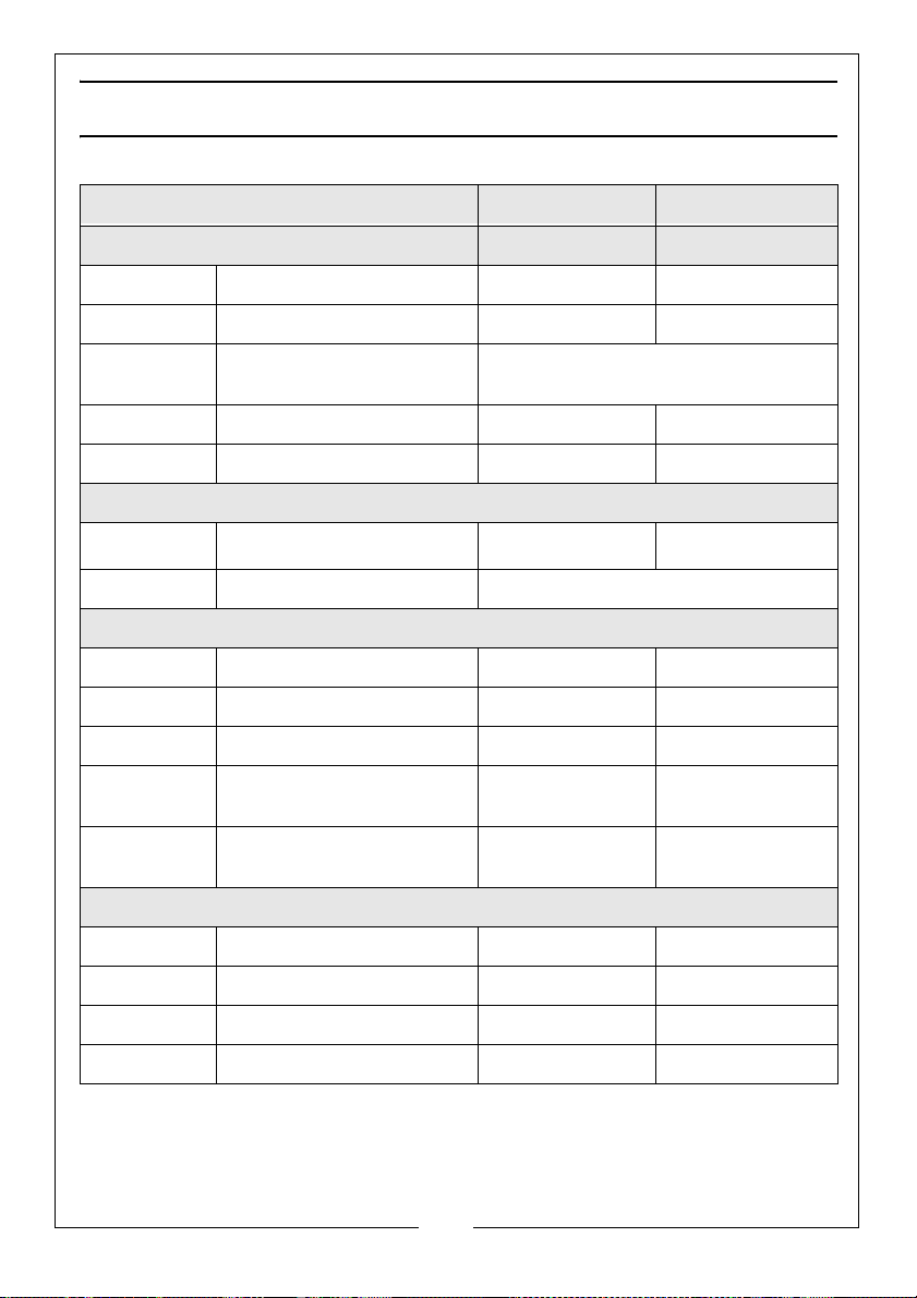
SPECIFICATIONS
Model PLS190N PLS260N
Engine
Engine Model 200F(D) 390F(D)
Power (HP) 6.5 13
Engine type Petrol (unleaded)
Starting system Recoil Recoil
Fuel Capacity (L) 3.5
Water supply
Max. feed temperature
Min. feed volume
Performance Data
Working pressure 165 Bar 235 Bar
Max. permissible pressure 186 Bar 260 Bar
Max. water flow (l/min.) 12.6 16.5
Measured sound power
le
Guaranteed sound power
le
Dimensions
Length (mm) 950 1075
Width (mm) 590 660
Height (mm) 620 760
Weight (k g) 48 60.5
vel L
vel L
WA dB
WA dB
6
o
50
C 50oC
5 gallons per minute at 20 PSI
99 107
101
108
21
Parts & Service: 020 8988 7400 / E-mail: [email protected] or [email protected]
Page 22
Page 23
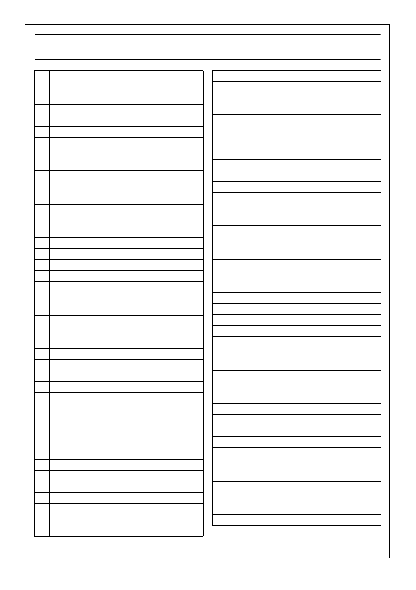
PARTS LIST
PLS190N
1 Drain Plug
2 Gasket 17 .5x12x2
3 Screw
4 Crankcase cover
5 0-ring 20.4X2.4
6 Side glass
7 Fix clip
8 0-ring 104X3
9 Ve n t e d o i l p l u g
10 0-ring 11.6X2.4
11 Bolt M8x16
12 Crankshaft cover
13 0-ring 51 .8x2.2
14 Snap ring
15 Ball bearing 6304
16 Crankshaft
17 Connecting rod
18 Fix pin
19 Ceramic plunger
20 Crankcase
21 Needle bearing 4907
22 Flange
23 Oil seal 40x52x7
24 Bolt M8x20
25 Oil seal
26 Retainer ring
27 0-ring 26. 7x1 . 78
28 Low pressure seal
29 Seal compaction ring
30 Seal Compaction flake
31 High-pressure seal
32 Supporting ring
33 Plastic cap
34 Knob
35 Spring
36 Spring seat
37 Jam nut
38 Fix screw M4x4
39 Unloader Valve
40 Valve Se a t
41 0-ring 9.25x1. 78
42 0-ring 18.2x2.4
RKPLS190N01
RKPLS190N02
RKPLS190N03
RKPLS190N04
RKPLS190N05
RKPLS190N06
RKPLS190N07
RKPLS190N08
RKPLS190N09
RKPLS190N10
RKPLS190N11
RKPLS190N12
RKPLS190N13
RKPLS190N14
RKPLS190N15
RKPLS190N16
RKPLS190N17
RKPLS190N18
RKPLS190N19
RKPLS190N20
RKPLS190N21
RKPLS190N22
RKPLS190N23
RKPLS190N24
RKPLS190N25
RKPLS190N26
RKPLS190N27
RKPLS190N28
RKPLS190N29
RKPLS190N30
RKPLS190N31
RKPLS190N32
RKPLS190N33
RKPLS190N34
RKPLS190N35
RKPLS190N36
RKPLS190N37
RKPLS190N38
RKPLS190N39
RKPLS190N40
RKPLS190N41
RKPLS190N42
43 Valve housing
44 Soap suction nozzle
45 0-ring 4.4 7x1. 78
46 Steel ball
47 Spring
48 Val v e p l u g
49 Steel ball
50 Spring
51 0-rino18 .2x2 .4
52 Outlet banjo bolt
53 0-ring 11.3x2.4
54 0-ring 4.2x2 .4
55 Checking valve
56 Spring
57 0-ring 14x1.9
58 Outlet quick connector
59 Inlet banjo bolt
60 0-ring 18.2x2.4
61 By-pass housing
62 Swivel nut
63 Inlet connector
64 Inlet water filter
65 0-ring 23.4x2.4
66 Val v e P l u g
67 0-ring 18x2.65
68 Checking valve assy
69 0-ring 15.54x2.62
70 Outlet plug
71 Inlet plug
72 Manifold head
73 Bolt M8x60
74
Filter RKPLS190N74
75
Chemical Inlet Hose RKPLS190N75
76
Pump Fix Bolt RKPLS190N76
77
Pump Assy RKPLS190N77
78
High-pressure Hose RKPLS190N78
79
Gun RKPLS190N79
80
Wand RKPLS190N80
81
Rubber Foot RKPLS190N81
82
Water Inlet Hose RKPLS190N82
83
Wheel RKPLS190N83
RKPLS190N43
RKPLS190N44
RKPLS190N45
RKPLS190N46
RKPLS190N47
RKPLS190N48
RKPLS190N49
RKPLS190N50
RKPLS190N51
RKPLS190N52
RKPLS190N53
RKPLS190N54
RKPLS190N55
RKPLS190N56
RKPLS190N57
RKPLS190N58
RKPLS190N59
RKPLS190N60
RKPLS190N61
RKPLS190N62
RKPLS190N63
RKPLS190N64
RKPLS190N65
RKPLS190N66
RKPLS190N67
RKPLS190N68
RKPLS190N69
RKPLS190N70
RKPLS190N71
RKPLS190N72
RKPLS190N73
23
Parts & Service: 020 8988 7400 / E-mail: [email protected] or [email protected]
Page 24
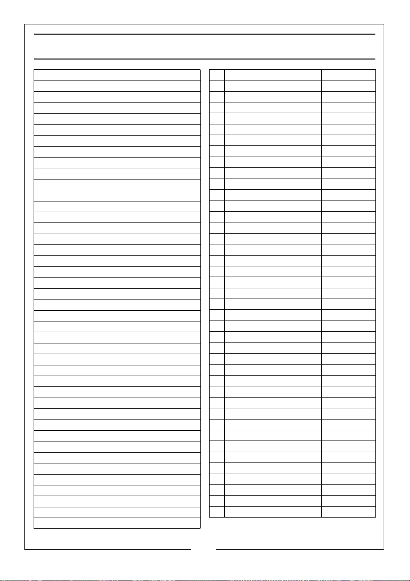
PARTS LIST
Drain Plug
1
Gasket 17 .5x12x2
2
Screw
3
Crankcase cover
4
0-ring 20.4X2.4
5
Side glass
6
Fix clip
7
0-ring 104X3
8
Vented oil plug
9
0-ring 11.6X2.4
10
Bolt M8x16
11
Crankshaft cover
12
0-ring 51 .8x2.2
13
Snap ring
14
Ball bearing 6304
15
Crankshaft
16
Connecting rod
17
Fix pin
18
Ceramic plunger
19
Crankcase
20
Needle bearing 4907
21
Flange
22
Oil seal 40x52x7
23
Bolt M8x20
24
Oil seal
25
Retainer ring
26
0-ring 26. 7x1 . 78
27
Low pressure seal
28
Seal compaction ring
29
Seal Compaction flake
30
High-pressure seal
31
Supporting ring
32
Plastic cap
33
Knob
34
Spring
35
Spring seat
36
Jam nut
37
Fix screw M4x4
38
Unloader Valve
39
Valve Se a t
40
0-ring 9.25x1. 78
41
0-ring 18.2x2.4
42
PLS260N
RKPLS260N01
RKPLS260N02
RKPLS260N03
RKPLS260N04
RKPLS260N05
RKPLS260N06
RKPLS260N07
RKPLS260N08
RKPLS260N09
RKPLS260N10
RKPLS260N11
RKPLS260N12
RKPLS260N13
RKPLS260N14
RKPLS260N15
RKPLS260N16
RKPLS260N17
RKPLS260N18
RKPLS260N19
RKPLS260N20
RKPLS260N21
RKPLS260N22
RKPLS260N23
RKPLS260N24
RKPLS260N25
RKPLS260N26
RKPLS260N27
RKPLS260N28
RKPLS260N29
RKPLS260N30
RKPLS260N31
RKPLS260N32
RKPLS260N33
RKPLS260N34
RKPLS260N35
RKPLS260N36
RKPLS260N37
RKPLS260N38
RKPLS260N39
RKPLS260N40
RKPLS260N41
RKPLS260N42
Valve housing
43
Soap suction nozzle
44
0-ring 4.4 7x1. 78
45
Steel ball
46
Spring
47
Valve pl u g
48
Steel ball
49
Spring
50
0-rino18 .2x2 .4
51
Outlet banjo bolt
52
0-ring 11.3x2.4
53
0-ring 4.2x2 .4
54
Checking valve
55
Spring
56
0-ring 14x1.9
57
Outlet quick connector
58
Inlet banjo bolt
59
0-ring 18.2x2.4
60
By-pass housing
61
Swivel nut
62
Inlet connector
63
Inlet water filter
64
0-ring 23.4x2.4
65
Valve Pl ug
66
0-ring 18x2.65
67
Checking valve assy
68
0-ring 15.54x2.62
69
Outlet plug
70
Inlet plug
71
Manifold head
72
Bolt M8x60
73
RKPLS260N43
RKPLS260N44
RKPLS260N45
RKPLS260N46
RKPLS260N47
RKPLS260N48
RKPLS260N49
RKPLS260N50
RKPLS260N51
RKPLS260N52
RKPLS260N53
RKPLS260N54
RKPLS260N55
RKPLS260N56
RKPLS260N57
RKPLS260N58
RKPLS260N59
RKPLS260N60
RKPLS260N61
RKPLS260N62
RKPLS260N63
RKPLS260N64
RKPLS260N65
RKPLS260N66
RKPLS260N67
RKPLS260N68
RKPLS260N69
RKPLS260N70
RKPLS260N71
RKPLS260N72
RKPLS260N73
74 Filter RKPLS260N74
75 Chemical Inlet Hose RKPLS260N75
76 Pump Fix Bolt RKPLS260N76
77 Pump Assy RKPLS260N77
78 High-pressure Hose RKPLS260N78
79 Gun RKPLS260N79
80 Wand RKPLS260N80
81 Rubber Foot RKPLS260N81
82 Water Inlet Hose RKPLS260N82
83 Wheel RKPLS260N83
24
Parts & Service: 020 8988 7400 / E-mail: [email protected] or [email protected]
Page 25
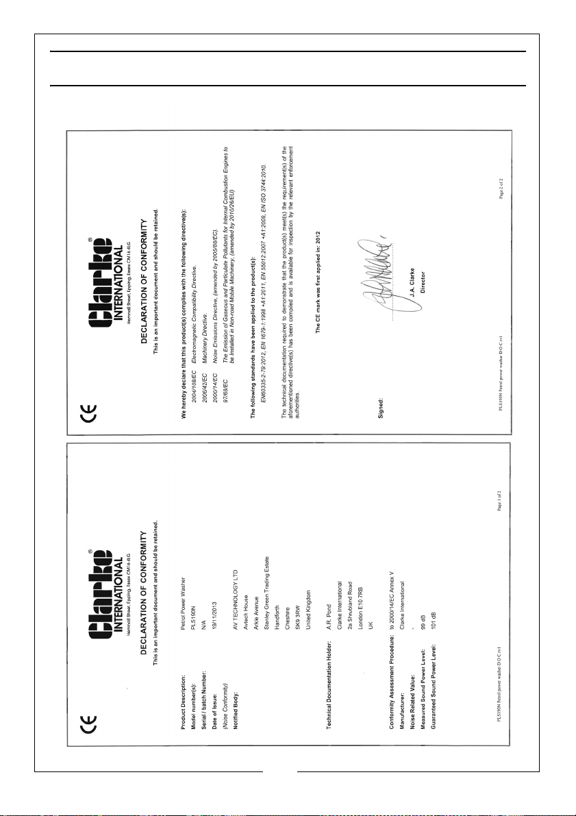
PLS190N DECLARATION OF CONFORMITY
25
Parts & Service: 020 8988 7400 / E-mail: [email protected] or [email protected]
Page 26
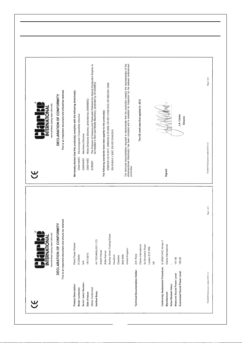
PLS260N DECLARATION OF CONFORMITY
26
Parts & Service: 020 8988 7400 / E-mail: [email protected] or [email protected]
Page 27
Page 28
 Loading...