

Page 1
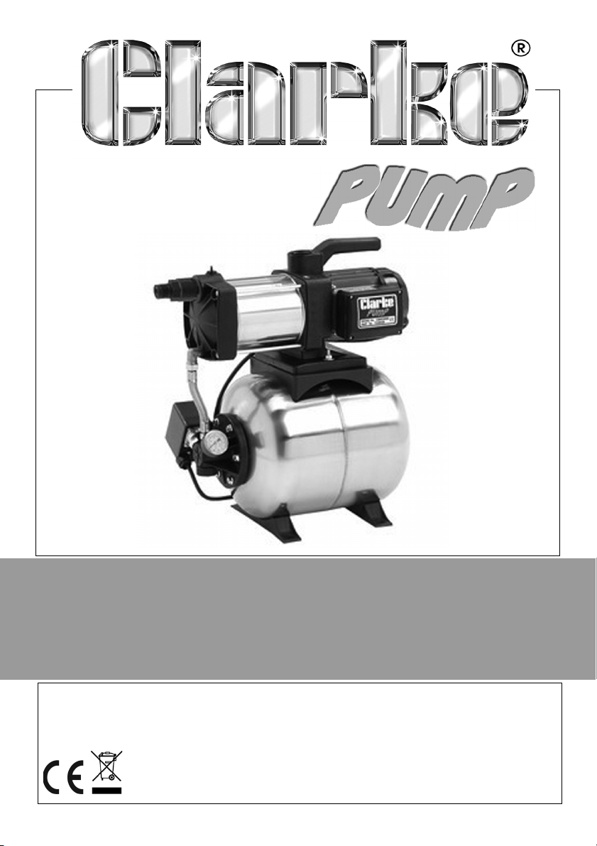
BOOSTER PUMP
MODEL NO: CBM250SS
PART NO: 7238020
OPERATION & MAINTENANCE
INSTRUCTIONS
ORIGINAL INSTRUCTIONS GC1220
Page 2
INTRODUCTION
Thank you for purchasing this CLARKE water pump. which is a general purpose
pump, suitable for a variety of applications involving the transfer of clean,
cold water ONLY (up to a maximum of 35
applications.
Please read this manual thoroughly and ensure you are familiar with all
aspects relating to your particular pump before its connection and use. This
will ensure the safe and proper installation of the pump and assist it in
providing a long, trouble free performance.
Please keep these instructions in a safe place for future reference.
o
C) for domestic and gardening
GUARANTEE
This product is guaranteed against faulty manufacture for a period of 12
months from the date of purchase. Please keep your receipt which will be
required as proof of purchase.
This guarantee is invalid if the product is found to have been abused or
tampered with in any way, or not used for the purpose for which it was
intended.
Faulty goods should be returned to their place of purchase, no product can
be returned to us without prior permission.
This guarantee does not effect your statutory rights.
ENVIRONMENTAL RECYCLING POLICY
Through purchase of this product, the customer is taking on the
obligation to deal with the WEEE in accordance with the WEEE
regulations in relation to the treatment, recycling & recovery and
environmentally sound disposal of the WEEE.
In effect, this means that this product must not be disposed of with general
household waste. It must be disposed of according to the laws governing
Waste Electrical and Electronic Equipment (WEEE) at a recognised disposal
facility.
2
Parts & Service: 020 8988 7400 / E-mail: [email protected] or [email protected]
Page 3
SPECIFICATION
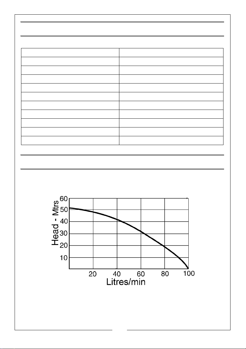
Maximum Delivery 100 l/min
Maximum Head 60 m
Maximum Suction Lift 9 m
On/Off Pressure 3.5/5.2 Bar
Ingress Protection Rating IPx4
Supply 230V ~ 50Hz
Rated Power 1250 W
Tank Capacity 24 Litres
Outlet Thread Size 1” BSP
Weight 19.2 kg
Sound Power Level 73 dB LpA
PUMP PERFORMANCE CURVE
3
Parts & Service: 020 8988 7400 / E-mail: [email protected] or [email protected]
Page 4
GENERAL SAFETY PRECAUTIONS
Before using this equipment it is in your own interest to read and pay attention
to the following safety rules.
WARNING: ALWAYS CONNECT THE PUMP TO AN EARTHED POWER SUPPLY
VIA AN RCD.
1. ALWAYS keep the working area clean and well lit. Floors should always be
kept clear. Cluttered or dark areas invite accidents.
2. NEVER over-reach. Keep your proper footing and balance at all times
when installing or maintaining the pump.
3. NEVER direct any water discharge towards electrical wiring or equipment.
4. ALWAYS thoroughly familiarise yourself with this pump & its operation, and
follow all instructions in this manual. Never allow persons unfamiliar with
these instructions to instal or operate the pump.
5. ALWAYS ensure that the pump is properly installed to prevent it from moving
during operation, and that the immediate area surrounding the pump is
kept clear.
6. ALWAYS maintain the pump with care and keep it clean for best / safest
performance.
7. NEVER modify this pump in any way. Use it ONLY for the purpose for which it
is designed.
8. NEVER use for pumping flammable liquids or corrosive chemicals. This
pump is designed to pump clean water only.
9. ALWAYS have the pump serviced by your local dealer, using only identical
replacement parts. This will ensure the safety of the pump is maintained.
The use of non standard parts could be hazardous.
10. NEVER use this product if any part is damaged. Have it inspected and
repaired by your local Clarke dealer. Always turn the pump off before
carrying out any maintenance.
11. NEVER allow the pump to run dry.
CAUTION: THIS PUMP IS NOT A SUBMERSIBLE PUMP. ON NO ACCOUNT
SHOULD IT EVER BE IMMERSED IN WATER.
4
Parts & Service: 020 8988 7400 / E-mail: [email protected] or [email protected]
Page 5
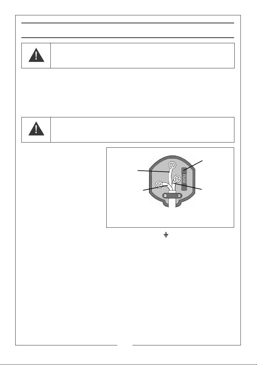
ELECTRICAL INSTALLATION
Plug must be BS1363/A approved.
Always fit
Ensure that the outer sheath of
Neutral
(Blue)
Live
(Brown)
Earth
(Green and
a 13 Amp
the cable is firmly held by the clamp
fuse.
Yel low)
WARNING: READ THESE ELECTRICAL SAFETY INSTRUCTIONS
THOROUGHLY BEFORE CONNECTING THE PRODUCT TO THE MAINS
SUPPLY.
Connect the mains lead to a standard, 230 Volt (50Hz) electrical supply
through an approved 13 amp BS 1363 plug or a suitably fused isolator switch.
If the plug has to be changed because it is not suitable for your socket, or
because of damage, it must be removed and a replacement fitted, following
the wiring instructions shown below. The old plug must be discarded safely, as
insertion into a power socket could cause an electrical hazard
WARNING: THE WIRES IN THE POWER CABLE OF THIS PRODUCT ARE
COLOURED IN ACCORDANCE WITH THE FOLLOWING CODE:
BLUE = NEUTRAL BROWN = LIVE YELLOW AND GREEN = EARTH
The colours of the wires in
the power cable must
agree with the markings on
the plug.
• Connect the BLUE wire
to the terminal
marked N.
• Connect the BROWN
wire to the terminal
marked L.
• Connect the YELLOW
AND GREEN wire to the terminal marked E or .
AN APPROVED RESIDUAL CURRENT DEVICE (RCD) WHICH HAS A TRIPPING
CURRENT OF LESS THAN 30 mA MUST BE USED.
If you are not sure consult a qualified electrician.
.
Parts & Service: 020 8988 7400 / E-mail: [email protected] or [email protected]
5
Page 6
INSTALLATION OF THE PUMP
IMPORTANT: The pump MUST NOT be connected to the mains power supply
until all hose/pipe installations are completed.
If any part of the system is to be connected to the mains water supply, do
ensure that you comply with your local water authority regulations.
Because of the variety of possible installations, no plumbing accessories are
supplied as standard with your pump. However, accessories designed
specifically for this range of pumps are available from your CLARKE dealer.
The pump must always be installed and operated in a horizontal position i.e.
with the outlet port facing vertically upwards. The fixing holes in the base
should be used as necessary to secure the pump firmly in its operating
position. Also, ensure that there is adequate air circulation around the motor.
Avoid situations where there is the risk of water coming into contact with the
outside of the pump. Neither the motor or the terminal box are designed to be
waterproof.
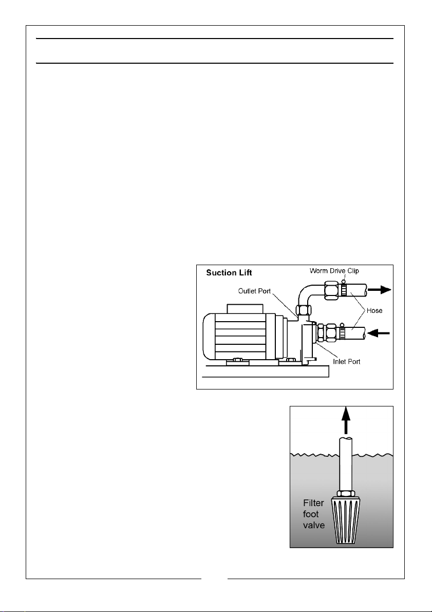
These notes are for guidance on
how to achieve a proper
working system.
The schematic diagram
opposite illustrates a typical
pipework installation.
The suction lift i.e. the vertical
distance between the water
level and the pump should not
exceed the distance specified
for your pump.
A foot valve and filter should be fitted to the lower
end of the suction hose, as illustrated below, so as to
help retain water in the suction system and to
prevent the possibility of large foreign bodies entering
the pump body.
A 1” BSP hose adapter will be required for connection
to the inlet port. This is available from your dealer.
The performance of your pump will be effected by
the diameter of the inlet pipe - any restriction will
greatly reduce the flow. We strongly recommend
that you use a diameter pipe which is as large as
practicable, with a suitable reducer for connection
to the 1” BSP inlet adapter.
6
Parts & Service: 020 8988 7400 / E-mail: [email protected] or [email protected]
Page 7

The delivery hose should be attached to the outlet adapter which is supplied.
A gate valve may be installed in-line on the delivery side of the pump which
can be set as required to regulate the flow of water. Do not place any such
restriction on the suction side of the pump unless it is an isolator valve in a
gravity fed system.
It is IMPORTANT to note also that this pump should not be operated with the
delivery valve completely closed.
To prevent unnecessary strain or possible distortion to the pump, ensure that
adequate support is provided to the hoses and/or pipes. Remember they will
be considerably heavier when filled with water.
Should sand, chemical or other contaminants come into contact with the
pump, flush through with cold clean water as soon as possible.
Protect the pump and pipework from freezing. The formation of ice may
cause serious damage.
Where the pump is to be a permanent fixture, the fittings to the pump MUST be
flexible, i.e. a short piece of hose should be inserted between rigid metal
pipework and the pump.
It is strongly recommended that in addition to the coarser foot filter, an inlet
filter should be fitted to prevent the possibility of any foreign body from
entering the pump. This is particularly important in the case of multi- stage
pump such as the CBM250SS. A filter specifically designed for all pumps in the
range is available from your CLARKE dealer.
The filter bowl is transparent allowing a visual check as to the condition of the
filter cartridge. The filter cartridge is a washable net type with a rated filtration
of 60 microns, suitable for the efficient removal of suspended particles such as
sand. The filter is NOT designed to filter mud, sludge etc.
This pump is provided with a non-return valve connected to the inlet port.
Screw the non return valve into the inlet port, ensuring the arrow, stamped on
the valve points inwards towards the inlet port. Tighten the valve, BUT DO NOT
OVERTIGHTEN, then screw the filter on to the valve - again DO NOT
OVERTIGHTEN.
The filter should hang vertically when completed.
These units operate as BOOSTER pumps by utilising an air chamber with a
pressure regulator to provide a constant pressure at the outlet.
The pump will automatically cut in when the water pressure reduces to 2.0 Bar,
and cut out when the pressure reaches 3.5 Bar. (These pressures are 3.5 and
5.2 bar respectively for Model CBM250SS). These pressures are factory set and
must not be altered. The pump may continue to operate for a short while,
after the tap is turned off, until the cut-out pressure is reached.
7
Parts & Service: 020 8988 7400 / E-mail: [email protected] or [email protected]
Page 8

In order for the system to operate correctly it is necessary to pressurise the air
chamber to 1.5 Bar (22psi), which is carried out as follows:
Unscrew the large protection cap on the end of the air chamber to reveal the
air valve and use an air line or foot pump to charge the chamber to the
specified pressure, checking with a standard air pressure gauge until satisfied.
Remember to replace the protective cap when completed.
IMPORTANT: This procedure MUST be carried out BEFORE connecting to the
water supply.
PRIMING
When suction lift is used to draw water into the pump it is essential that all
connections and hoses are completely air tight, otherwise the system will not
work.
Although the pump is a ‘self priming’ type, it is nevertheless necessary to
completely fill the inlet side of the pump with water before being started for
the first time, or if the system has been drained for maintenance or repair
purposes. This is known as priming the pump and is carried out as follows:-
1. 1.Locate and remove the small filler plug, situated on the top of the pump
chamber, and slowly fill the pump with water until all air is expelled.
NOTE: If a filter is fitted to your pump it is recommended that you remove
the brass plug on top of the unit and fill the bowl with water.
2. Adjust any device which may be fitted to the outlet side of the pump, so as
to ensure as great a flow as possible.
3. Switch on the pump and check for leaks. Water should start to flow through
the system after a short while. If, after 2-3 minutes, depending upon the
suction depth, water does not flow, check to ensure:
• The inlet pipe is completely secure and completely free from
defects. Even a pin hole could prevent the pump from drawing
water. This is the most common problem encountered when
operating water pumps.
• The pump body has been primed correctly and is completely filled
with water.
NOTE: If the pump is gravity or pressure fed, priming will not be
necessary, as the pressure of water will purge the system of air.
It is essential that all connections and hoses are completely air tight, otherwise
the system will not work.
8
Parts & Service: 020 8988 7400 / E-mail: [email protected] or [email protected]
Page 9
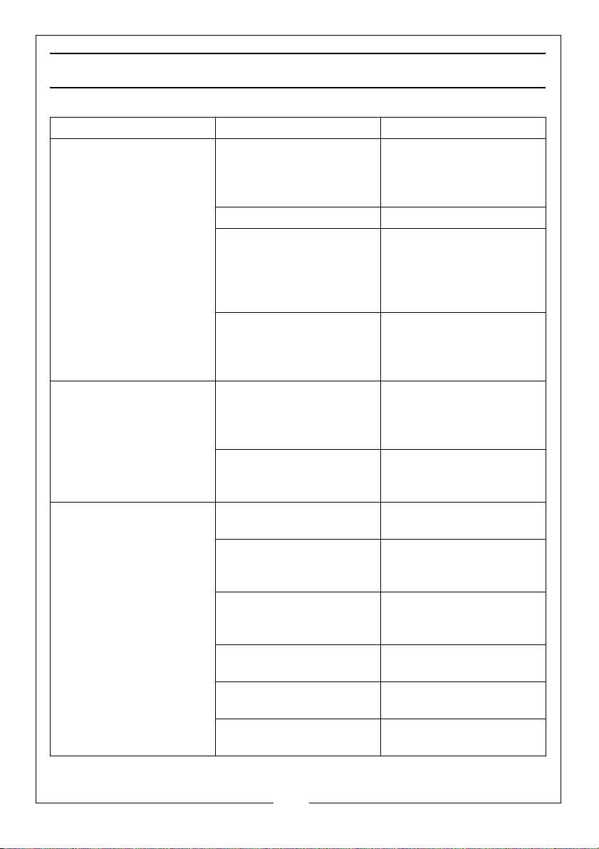
TROUBLESHOOTING
Problem Cause Solution
Pump does not run. Thermal protection has
been activated.
Faulty power connection Insert plug securely.
No mains supply. Check fused power
Impeller seized/blocked Disconnect pump from
Pump fails to prime Air leaks through suction
hose joints (damaged
hose or damaged
clamp.)
Blocked inlet hose Check pipeline for block-
Pump runs but gives poor
output
Congested material
inside pump
Suction or delivery line
obstructed.
Inlet pipe leakage. Check inlet pipe and
Air leaks through
damaged seal.
Impeller damaged and
making poor seal.
Impeller / mechanical
seal is badly worn.
If the motor has overheated, wait for it to cool
down before trying
again.
supply and replace fuse
if necessary (check fuse
rating). Check circuit
breaker.
power supply.
Investigate cause and
clear blockage
Repair connections/
replace hose as
necessary.
age. Check any inlet
valve fitted is fully open.
Clean out & backflush
pump.
Remove obstruction and
ensure there are no kinks
in delivery line.
connector for leaks.
Tighten as required.
Renew seal.
Return to your CLARKE
dealer for repair.
Return to your CLARKE
dealer for repair.
9
Parts & Service: 020 8988 7400 / E-mail: [email protected] or [email protected]
Page 10
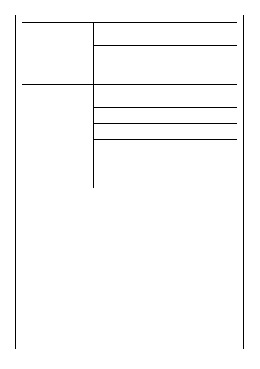
High friction losses in the
suction line.
Avoid unnecessary
curves, restrictions or
valves
Pump badly sited resulting in suction lift too high
Set pump as close as
possible to the level of
the water to be pumped
Sudden loss of flow. Blockage of inlet pipe Check pipeline for
blockage.
Undue vibration or noise. Excessive flow of water. Decrease flow of water.
by adjusting inlet/outlet
valves in system.
Resistance in inlet pipe
caused by obstruction.
Loose rotating
component
Installation of pump is
unstable.
Air pocket in pump or
pipeline.
Check pipe and clean
out as necessary
Return to your dealer for
repairs.
Stop pump and
re-position.
Release plug in impeller
housing to release air.
Damaged impeller Return to your CLARKE
dealer for repair.
10
Parts & Service: 020 8988 7400 / E-mail: [email protected] or [email protected]
Page 11

MAINTENANCE & CLEANING
The only maintenance required is a regular inspection to ensure that debris is
not blocking the passage of water through the pump.
If you suspect the pump is blocked by silt, leaf debris etc, disconnect it from
the power supply and back-flush to clear any blockage using a garden hose.
• You will need to disconnect the outlet hose to do this.
Always keep the pump in a clean condition, checking regularly for loose bolts
or a damaged power cable etc.
The pump should not be taken apart by the user if overhaul is required, but
should be taken to your nearest CLARKE dealer for repair.
11
Parts & Service: 020 8988 7400 / E-mail: [email protected] or [email protected]
Page 12
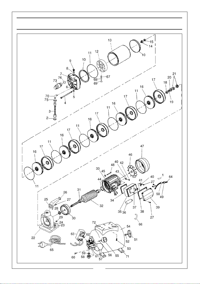
COMPONENT PARTS CBM250SS
12
Parts & Service: 020 8988 7400 / E-mail: [email protected] or [email protected]
Page 13
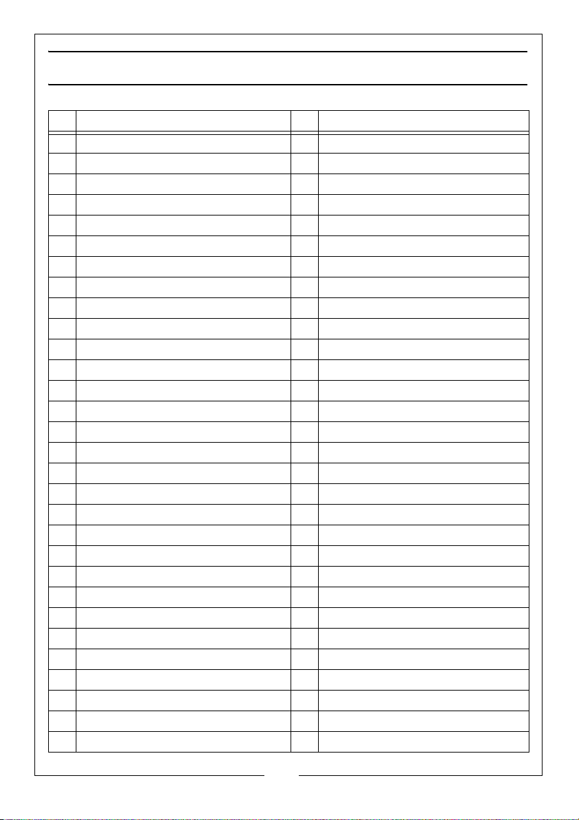
COMPONENT PARTS LIST
ID DESCRIPTION ID DESCRIPTION
1 Terminal 31 Bearing
2 Joint 32 Shaft with bearings
3 Flexible pipe 33 Stator
4 Cross screw 34 Gasket
5 Spring washer 35 Capacitor holder
6 O-ring 36 Capacitor
7 Flange MC1” gas 37 Screw
8 O-ring 38 O-ring
9 Screw 3/8” gas 39 Capacitor holder cover
10 Joint 40 Spring washer
11 O-ring 41 Cable fastener
12 Counterflange 42 Screw
13 Cylinder 43 Washer
14 Nut 44 Wave washer
15 Washer 45 Spring Washer
16 Impellor 46 Fan Blades
17 Diffuser 47 Fan Cover
18 Washer 48 Screw
19 Ring 49 Nut
20 Washer 50 Joint
21 Mechanical Seal 51 Valve Cap
22 Pump Housing 52 Valve
23 Washer 53 Screw
24 Nut 54 Tank Shell SS
25 Handle 55 Pressure gauge (manometer)
26 Handle Cap 56 O-ring
27 Screw 57 Gauge
28 Joint 58 1” Cap
29 Nut 59 O-ring
30 Anterior Flange 60 Screw
13
Parts & Service: 020 8988 7400 / E-mail: [email protected] or [email protected]
Page 14

ID DESCRIPTION ID DESCRIPTION
61 4-way Flange 69 Adjuster
62 O-ring 70 Elbow
63 Pressure Switch 71 Foot
64 Cable 72 Bracket
65 Cable 73 Non-return valve
66 Clip 74 O-ring
67 Spring 75 Joint
68 O-ring
ACCESSORIES
o
1” BSP Hose adaptor 90
1” BSP Plastic Foot Valve Filter FVF10 Part No:7950680
1” dia Reinforced Suction/Delivery Hose Part No:7955010
1” dia Layflat Delivery Hose Part No:7955110
bend (female)
Part No:7950190
14
Parts & Service: 020 8988 7400 / E-mail: [email protected] or [email protected]
Page 15
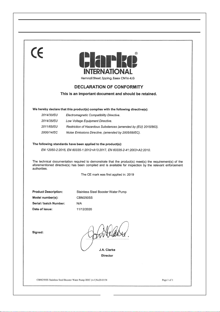
DECLARATION OF CONFORMITY
15
Parts & Service: 020 8988 7400 / E-mail: [email protected] or [email protected]
Page 16

 Loading...