

Page 1
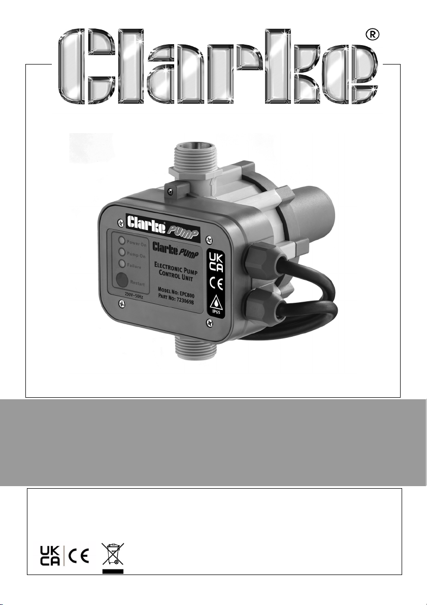
ELECTRONIC PUMP CONTROLLER
MODEL NO: EPC800
PART NO: 7230698
OPERATION & MAINTENANCE
INSTRUCTIONS
ORIGINAL INSTRUCTIONS GC04/22 - REV 3
Page 2

INTRODUCTION
Thank you for purchasing this Clarke EPC800.
Before attempting to use this product, please read this manual thoroughly and
follow the instructions carefully. In doing so you will ensure the safety of yourself
and that of others around you, and you can look forward to your purchase
giving you long and satisfactory service.
Please keep these instructions in a safe place for future reference.
APPLICATIONS
This EPC800 can be used to convert pumps into automatic booster sets.
The EPC800 provides 2 main functions:
1. It provides automatic operation of your pump.
• This in-line device maintains water pressure from booster pumps by
instantly sensing water usage and automatically starting or stopping
the pump.
2. It protects the pump from running dry.
• The EPC800 has a built in safety circuit, which switches the pump OFF
when there is no water flow.
GUARANTEE
This product is guaranteed against faulty manufacture for a period of 12
months from the date of purchase. Please keep your receipt which will be
required as proof of purchase.
This guarantee is invalid if the product is found to have been abused or
tampered with in any way, or not used for the purpose for which it was
intended.
Faulty goods should be returned to their place of purchase, no product can
be returned to us without prior permission.
This guarantee does not effect your statutory rights.
2
Parts & Service: 020 8988 7400 / E-mail: [email protected] or [email protected]
Page 3

SAFETY PRECAUTIONS
1. DO NOT attempt to modify or alter the controller in any way.
2. Observe all electrical precautions. DO NOT allow the EPC800 to be
submerged. Ensure it is protected from the elements at all times.
3. Read and comply with all precautions specified in your pump manual.
CONNECTING THE PUMP TO THE EPC800
The EPC800 is fitted with two cables.
1. One is fitted with a standard 13 amp plug.
• When connected to the mains supply, this cable carries the supply
to both the EPC800 and the pump.
2. The other cable should be fitted with a trailing socket (not supplied).
3. Insert the plug from the pump into the trailing socket.
IMPORTANT: If the EPC800 is to be connected to an outdoor electrical
supply, make sure that both the plug and the socket are of a BS approved
waterproof design and are protected from the elements.
3
Parts & Service: 020 8988 7400 / E-mail: [email protected] or [email protected]
Page 4
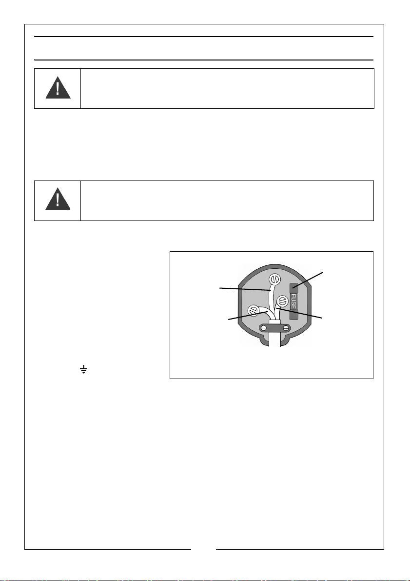
ELECTRICAL CONNECTIONS
Plug must be BS1363/A approved.
Always fit
Ensure that the outer sheath of
Neutral
(Blue)
Live
(Brown)
Earth
(Green and
a 13 Amp
the cable is firmly held by the clamp
fuse.
Yel low)
WARNING: READ THESE ELECTRICAL SAFETY INSTRUCTIONS
THOROUGHLY BEFORE CONNECTING THE PRODUCT TO THE MAINS
SUPPLY.
Connect the mains lead to a standard, 230 Volt (50Hz) electrical supply through an
approved 13 amp BS 1363 plug or a suitably fused isolator switch.
If the plug has to be changed because it is not suitable for your socket, or because of
damage, it must be removed and a replacement fitted, following the wiring instructions
shown below. The old plug must be discarded safely, as insertion into a power socket
could cause an electrical hazard
WARNING: THE WIRES IN THE POWER CABLE OF THIS PRODUCT ARE
COLOURED IN ACCORDANCE WITH THE FOLLOWING CODE:
BLUE = NEUTRAL BROWN = LIVE YELLOW AND GREEN = EARTH
If the colours of the wires in the power cable do not agree with the markings on the
plug.
• The BLUE wire must be
connected to the
terminal marked N or
coloured black.
•The BROWN wire must be
connected to the
terminal marked L or
coloured red.
• The YELLOW AND GREEN
wire must be connected
to the terminal marked E
or or coloured green.
We strongly recommend
that this product is connected to the mains supply through a Residual Current
Device (RCD)
If you are in any doubt regarding electrical installation, you should consult a
qualified electrician.
.
EXTENSION CABLES
The maximum length of cable should not exceed 25 metres, and the size of
the conductors must be AT LEAST the same size as that on the EPC800.
Ensure that all connections are well clear of the water.
Parts & Service: 020 8988 7400 / E-mail: [email protected] or [email protected]
4
Page 5
Page 6

OPERATION
STARTING
CAUTION: ENSURE THE PUMP IS FULLY PRIMED BEFORE SWITCHING ON.
SEE YOUR PUMP INSTRUCTION MANUAL FOR DETAILS.
You should always fit a non-return valve to the suction line. (A foot valve and
filter are available from your CLARKE dealer).
1. Close all taps on the discharge side of the pump.
2. After making sure that all precautions have been observed, switch on the
pump at the mains supply.
• The green “Power On” LED will light up and the yellow “Pump On”
LED will indicate that the pump has been started.
• The pump will continue to operate for a few seconds enabling the
system to fill and to reach the required pressure.
• If this amount of time is insufficient, the red LED “Failure” lights up. If
this happens, open a tap and keep the “Restart” button pressed
until the red LED goes off, then release the button and close the tap.
The EPC800 will stop the pump at its maximum pressure.
RUNNING
The EPC800 is programmed to perform all the pump control operations
automatically.
• If you open the outlet tap the EPC800 will detect a drop in pressure
and start the pump.
When operational breakdowns occur, such as water loss, obstruction of the
suction pipe, etc., the EPC800 recognizes the problem and the red “Failure”
led lights up at the same time as the power to the pump is cut to prevent
damage caused by dry running.
1. Switch off the EPC800 at the mains.
2. Rectify the problem.
3. Switch on the EPC800 at the mains and press the RESET button.
NOTE: The most common problems associated with water pump
operation are leaks on the SUCTION side of the pump. Even a pin
hole in the inlet hose is sufficient to seriously reduce suction.
6
Parts & Service: 020 8988 7400 / E-mail: [email protected] or [email protected]
Page 7
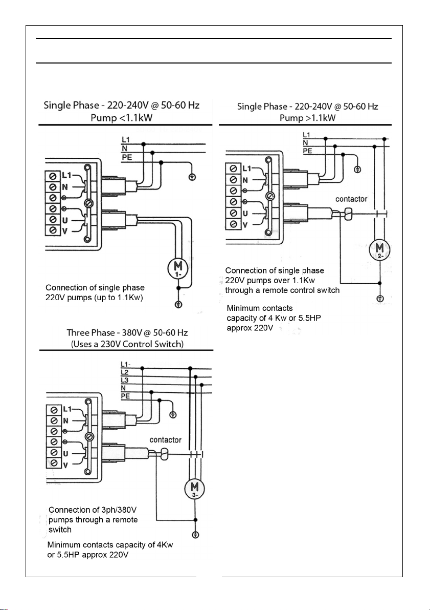
WIRING DIAGRAMS
FOR CONNECTING THE EPC800 TO DIFFERENT KINDS OF PUMPS MOTORS
7
Parts & Service: 020 8988 7400 / E-mail: [email protected] or [email protected]
Page 8

TROUBLESHOOTING
Problem Causes related to the EPC800. Other possible causes
The pump
does not start
The pump
does not stop
Intermittent
pump
working
The pump is
jammed
For other possible problems consult the pump instruction manual.
The internal PCB is broken Voltage failure
Pump jammed
Electric cables incorrectly
wired
The internal PCB is broken
The flow detector is blocked in
the upper position
The reset button is blocked
The pump is unable to provide
sufficient pressure
The internal PCB is broken
The pump does not provide
sufficient pressure
The internal PCB is broken
The pump provides a pressure
which is lower than the restarting
pressure
Presence of leaks which are
higher than the minimum
flow 0.6 I/min
Presence of leaks which are
lower than the minimum
flow 0.6 I/min
Water failure
suction problems
8
Parts & Service: 020 8988 7400 / E-mail: [email protected] or [email protected]
Page 9
SPECIFICATIONS
Input Voltage 220-240V
Frequency 50-60Hz
Maximum Current 10A
Maximum Flow Rate 83 l/min
Maximum Head 50 m
Max. Water Temp. 60°C
Protection Rating IP65
Maximum Operating Pressure 10 bar
Maximum Temperature Rating 60°C
Connection 1" BSP
ENVIRONMENTAL RECYCLING POLICY
Through purchase of this product, the customer is taking on the
obligation to deal with the WEEE in accordance with the WEEE
regulations in relation to the treatment, recycling & recovery and
environmentally sound disposal of the WEEE.
In effect, this means that this product must not be disposed of with general
household waste. It must be disposed of according to the laws governing
Waste Electrical and Electronic Equipment (WEEE) at a recognised disposal
facility.
9
Parts & Service: 020 8988 7400 / E-mail: [email protected] or [email protected]
Page 10
DECLARATION OF CONFORMITY
10
Parts & Service: 020 8988 7400 / E-mail: [email protected] or [email protected]
Page 11
ACCESSORIES
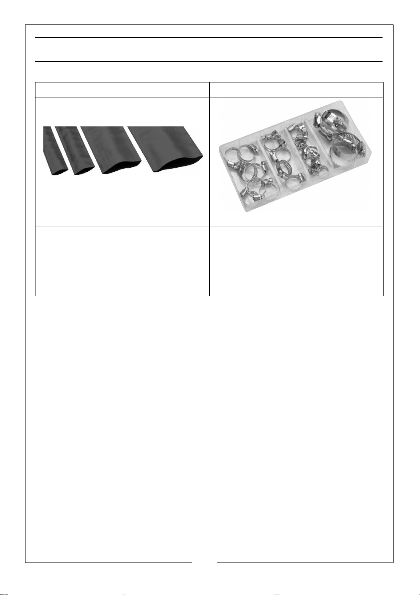
Layflat Hoses Assorted Hose Clip Set - CHT672
• Available in 100 metre coils or per
meter.
• Available in 1” - 3” Diameter.
• 26 piece assorted hose clip set in
various sizes, Including. 8 x16mm,
6 x 22mm, 4 x 25mm, 2 x 28mm,
2 x 35mm & 4 x 40mm clips.
• Zinc plated for corrosion
resistance.
11
Parts & Service: 020 8988 7400 / E-mail: [email protected] or [email protected]
Page 12

 Loading...