

Page 1
P-TEC VOICE PAGING SPEAKER
Back Box (Optional)
Volume Control
ct
S-525
INTRODUCTION
Clarity P-TEC Voice Paging Speakers are suitable
for voice paging as well as background music.
The S-525 is a 70 Volt model with adjustable taps
and volume control. P-TEC speakers consist of a
3.6 inch cone speaker mounted in a unique
surface-mount baffle. The baffle is designed for
mounting on acoustic tile, such as those normally
found in suspended-ceilings; and can be mounted
without cutting large holes in the tile. The mounting pins can be removed for mounting in a hard
ceiling. The speaker housing has screw holes for
securing speaker without mounting pins. Although
the P-TEC speakers are designed especially for
standard suspended ceilings, they can be used on
many types of ceiling materials. P-TEC speakers
are not suitable for use in plenum ceiling
environments.
DIMENSIONS/WEIGHT
• 8.00”Dia. x 2.50”D (20.32cm x 6.35cm)
1.25 lbs. (.57 kg)
INSTALLATION
Selecting the Power-Tap Wire
Issue 1
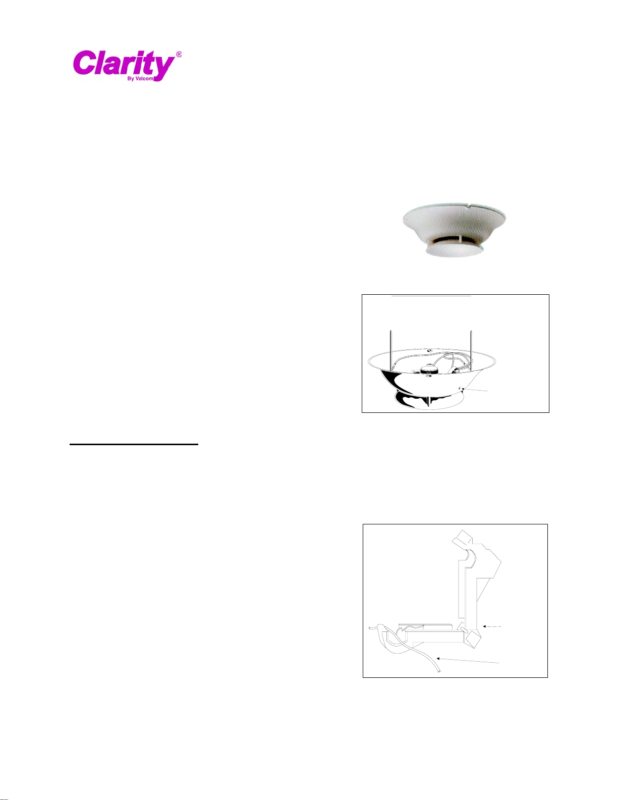
Figure 1. 70 Volt P-TEC Paging Speaker
3. Install the Quick-Connect connector on the
wire. Use pliers to close the connector over
the wire. The connector can be removed by
prying it open with a screwdriver, and can be
reused several times (See Figure 2).
1. Remove the Quick-Connect connector from
the accessory pack.
2. Select the desired power-tap wire:
Yellow = 1/4 Watt
Red = 1/2 Watt
Green = 1 Watt
White = 2 Watt
Blue = 4 Watt
Note: Refer to spacing chart (Figure 6) for recom-
mended speaker spacing.
Reusable
Quick-Conne
Connector
Tap Wire
Figure 2. Attaching the Reuseable Quick-Connect
Connector
1 947442
Page 2
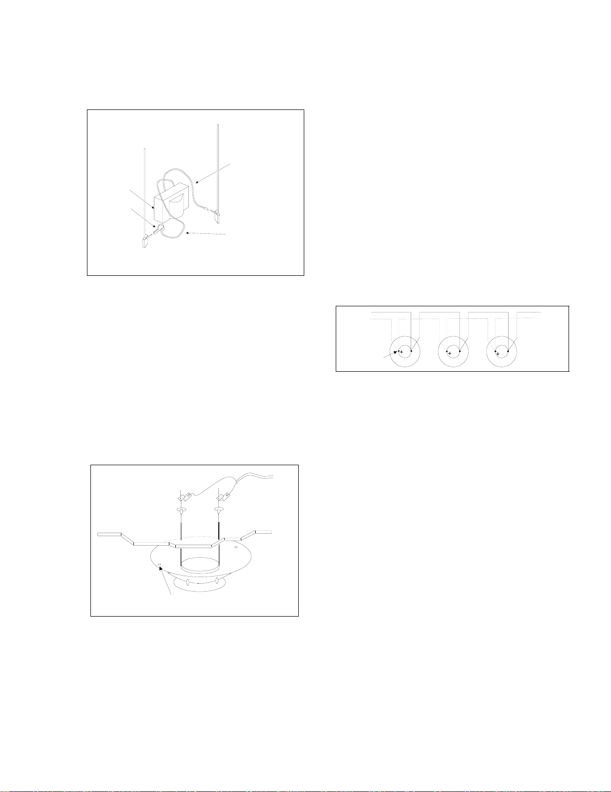
4. Connect the power-tap wire to the gold (+)
7
Q
tt
tt
tt
tt
tt
neatly inside speaker housing.
er
when spikes can not be used.
Gold ( + )
To Paging
Amplifier
To Next
Speaker
terminal (See Figure 3).
5. Arrange the unused power-tap wires neatly
inside the speaker housing and tape them to
the inside of the housing.
( - ) Silver
4. If necessary, adjust paging volume after installation. The volume control is located on the
side of the speaker. Use a small screwdriver to
turn the control.
5. Install the volume control cover found in the
accessory pack.
( + ) Gold
Black - Common
(Connected at Factory)
0V Transformer
Reusable
uick-Connect
Connector
Arrange unused wires
Power Tap Wires
Power Tap Wires
Yellow - 1/4 Watt
Yellow
Red - 1/2 Watt
Red
Green - 1 Watt
Green
White - 2 Watt
White
Blue - 4 Watt
Blue
Tap Wire
- 1/4 Wa
- 1/2 Wa
- 1 Wa
- 2 Wa
- 4 Wa
Figure 3. Connecting the Tap Wire
Suspended Ceiling
Note: Wrap wires around strain relief posts so
speaker wires will not pull free.
1. Lift the adjacent ceiling tile and slide it out of
the way.
2. Install the speaker by inserting the mounting
pins through the ceiling tile, and hold the
speaker in place.
3. Place the wire and washers, and speaker
mounting clips over mounting pins (so pins
slide through clips).
To
Red
Black
Amplifi
Note: The music volume should be adjusted at
the paging amplifier or music source.
Adjust paging before adjusting background
music.
Maintain Speaker Phasing
When using multiple speakers in a single run,
keep speakers in phase by connecting the
speaker wires to the same spike on each speaker
(Either wire can connect on either spike, as long
as the pattern is followed on each speaker). The
gold spike is the plus (+) terminal (See Figure 5).
Figure 5. Maintaining Speaker Phasing
Handling Shielded Speaker Cable
If you are using shielded speaker cable, splice the
shield wire at the speaker location so a continuous shield is maintained. When connecting a single speaker, or the last speaker on the run, clip
the shield wire where it emerges from the outer
insulation on the speaker cable.
Gold
Spike
Use mounting holes and screws
Silver
Spike
Figure 4. Clarity P-TEC Installation
Note: Washers provide isolation from the pins if
the back of the tile is covered with metal
foil.
TECHNICAL ASSISTANCE
When calling, have a VOM and a telephone test
set available and call from the job site.
Call (540) 767-1550 for Clarity Technical Support,
or call (540) 767-1555 for Valcom 24-hour Faxback System or visit our websites at
http://www.clarity-com.com and www.valcom.com.
Should repairs be necessary, attach a tag to the
unit clearly stating company name, address,
phone number, contact person and the nature of
the problem. Send the unit to:
Clarity
Repair and Return Dept.
5614 Hollins Road
Roanoke, VA 24019-5056
2
Page 3

NOISE
LEVEL
IN dB
55 dB
56 dB
57 dB
58 dB
59 dB
60 dB
61 dB
62 dB
63 dB
64 dB
65 dB
66 dB
67 dB
68 dB
69 dB
70 dB
71 dB
72 dB
73 dB
74 dB
75 dB
76 dB
77 dB
P-TEC SPEAKER PROJECTION DISTANCE
SOUND PRESSURE LEVELS AND WATTAGE SETTINGS FOR 70 VOLT SPK
SPL-76
.25 WATT
26
24
22
20
16
15
14
12
10
8
SPL-78
.50 WATT
24
22
20
16
15
14
12
10
8
SPL-80
1.0 WATT
24
22
20
16
15
14
12
10
8
SPL-83
2.0 WATT
24
22
20
16
15
14
12
10
8
SPL-86
4.0 WATT
MOUNTING
24
22
20
16
15
14
12
10
8
MINIMUM
HEIGHT
15 FT
10 FT
8 FT
P-TEC SPEAKERS ARE INTENDED FOR USE IN STANDARD 8 FOOT DROPPED CEILING TILE.
CEILING HEIGHTS OF MORE THAN 8 FEET OR HIGHER, NOISE LEVELS MAY REQUIRE LESS
THAN THE STANDARD 25 FOOT SPACING OR HIGHER TAP SETTINGS.
Figure 6
3
 Loading...