

Page 1
PREPARATION
Parts list
(Qty) Component
Preassembled
(1) Roto-molded subwoofer enclosure
(1) 8"; 2 ohm subwoofer
(1) 100W class "D" amplifier
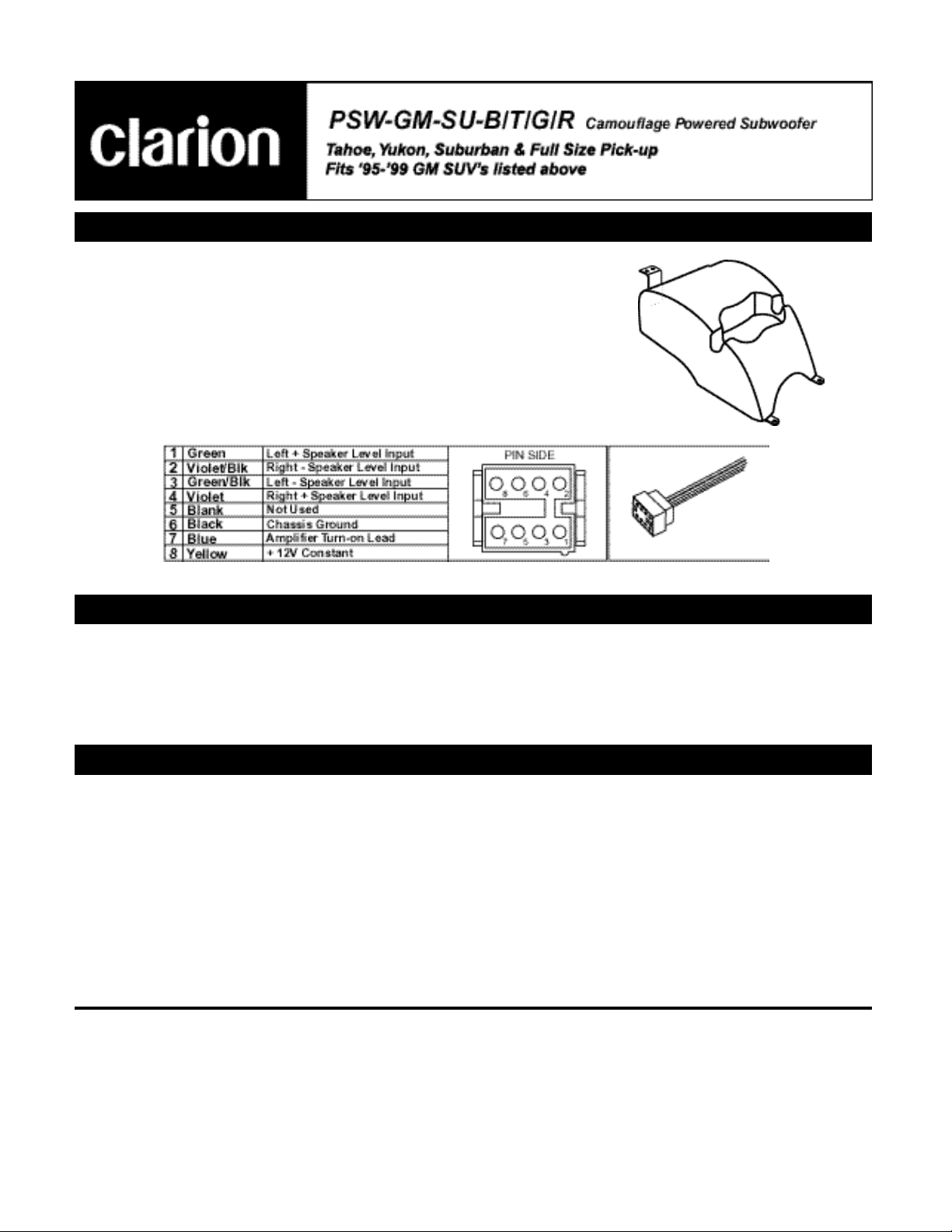
WIRING:
Note: Installer MUST disconnect speaker-input leads to amplifier when using line-level input
Loose Components
(1) 3’ wire harness w/ pigtail style connector
(2) 1" self taping Phillips screws
(1) 1/2" ground screw
(1) Star washer
(2) Flat 4 hole brackets
(1) L shaped bracket
(8) 3/4" pilot point Phillips screws
OVERVIEW
The Clarion Camouflage subwoofer system provides for the installation of a low frequency driver in an enclosure which
is powered by a small low current, high power class "D" (Digital) amplifier. The advantage to using this type of amplifier
is in the low current consumption of the amplifier at high power levels. The class "D" amplifier provided with this system
will produce a rated 100W into a 2 ohm load. The woofer supplied with this system uses a voice coil with rated impedance of 2 ohms, and therefore is not considered a standard woofer. Replacing the woofer with any driver having an
impedance greater than 2 ohms will yield lower power output from the amplifier, and is not recommended.
PROCEDURE
Proper installation of this product requires proper tools and knowledge of car audio principles. If you are not comfortable
performing any of the outlined tasks below, contact a professional installation facility to perform the work.
OUTLINE
• Remove the head unit.
• Connect the Clarion "T" harness between the radio and factory wiring and route the harness extension to transmis-
sion hump of the vehicle.
• Install subwoofer enclosure.
• Test subwoofer enclosure and head unit functions (fade, balance, dim, etc.).
• Adjust subwoofer gain.
THIS DEVICE COMPLIES WITH PART 15 OF THE FCC RULES. OPERATION IS SUBJECT TO THE FOLLOWING TWO CONDITIONS.
(1) THIS DEVICE MAY NOT CAUSE HARMFUL INTERFERENCE, AND
(2) THIS DEVICE MUST ACCEPT ANY INTERFERENCE RECEIVED, INCLUDING INTERFERENCE THAT MAY CAUSE UNDESIRED OPERATION.
1
Page 2
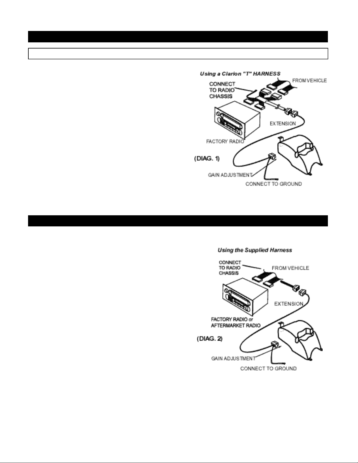
Ia. WIRING USING A CLARION “T” HARNESS
There are 2 methods to connect this product to the vehicle. Please refer to section Ia and Ib for each.
• STEP 1:
Remove the Radio.
• STEP 2:
Connect the "T" Harness.
A. Unplug factory wires from radio.
B. Plug the "T" harness in line with the radio wiring. SEE DIAGRAM 1.
C. Connect the BLACK wire on "T" harness to radio chassis.
• STEP 3:
Route the wire harness from the radio to transmission hump of the vehicle.
•STEP4:
Connect the amplifier ground wire to a clean chassis ground near the
subwoofer enclosure.
STEP 5:
TEST and SET the GAIN.
A. Turn on the system and be sure all speakers are working properly.
B. Set the subwoofer amplifier gain to a suitable level.
Ib. WIRING USING THE SUPPLIED HARNESS
• STEP 1:
Remove the Radio.
• STEP 2:
Connect the wires.
Yellow: Connect to Constant 12V Power
Black: Connect to Radio Ground or Chassis
Blue: Connect to Amp/Antenna Turn-on Lead
Green: Connect to Left Rear Speaker (+) Positive Lead
Green/Black: Connect to Left Rear Speaker (-) Negative Lead
Violet: Connect to Right Rear Speaker (+) Positive Lead
Violet/Black: Connect to Right Rear Speaker (-) Negative Lead
• STEP 3:
Route the wire harness from the radio to transmission hump of the vehicle.
•STEP 4:
Connect the amplifier ground wire to a clean chassis ground near the
subwoofer enclosure.
STEP 5:
TEST and SET the GAIN.
A. Turn on the system and be sure all speakers are working properly.
B. Set the subwoofer amplifier gain to a suitable level.
2
Page 3

II. RUN WIRE HARNESS
A. Route harness straight down from the radio to the vehicle floor.
B. Fold back carpet on transmission hump.
C. Put a small slit in the carpet about 12" away from the black floor
vents.
D. Route harness through the slit in the carpet.
E. Ground the 8" black wire to the vehicle floor (be sure to use a
wire wheel or sand paper if grounding to a painted surface).
III. INSTALL THE BRACKETS TO THE ENCLOSURE
A. Align the (2) flat 4-hole brackets to the dimples on the bottom of
the enclosure.
B. Attach each bracket with two pilot point screws (one hole of the
bracket should extend out past the enclosure).
C. Attach the “L” shaped bracket to the back of the enclosure; align
the two vertical slots on the bracket with the dimples on the back
of the enclosure.
IV. TEST THE ENCLOSURE
A. Plug in the Clarion “T” harness or hardwire the pigtail harness
behind the radio.
B. Place the enclosure into the vehicle (correct position is on the
transmission hump).
C. Plug in the wire harness to the enclosure.
D. Gain the subwoofer enclosure (gain pod is located on the ampli-
fier next to the wire harness connector, and is adjustable with a
Phillips screw driver).
3
Page 4

V. A TTACH THE ENCLOSURE TO VEHICLE
A. Be sure enclosure is in correct position.
B. Cut a “U” shaped slit in the carpet at the two front bracket loca-
tions.
C. Fold up carpet slits over the brackets.
D. Screw in the front two bracket to the vehicle floor (or duct work
depending on application) using the supplied 1" self-taping
screws.
E. Fold carpet slits back over to conceal the brackets.
F. Attach the rear ‘L’ bracket to the vehicle using (2) pilot point
screws. This will require a right-angle drill attachment with a #2
Phillips bit.
VI. REASSEMBLE THE VEHICLE
A. Make sure all the wires are hidden. Then do the process in
reverse order.
10 - PSWGMSU Rev. 1 (03/00)
Clarion Corporation of America
661 West Redondo Beach Blvd Gardena, CA 90247
800-Go-Clarion
www.clarion-usa.com © 2000 Clarion Corporation, Gardena, CA
4
 Loading...