

Page 1

Clarion'
CMRC1-BSS
CMRC1-SB
MARINE REMOTE-MOUNTED
CONTRQ~PJ\N~L
Owner's Manual/Installation Guide
Page 2
l:j
Page 3
1.
Intr4oduction··········,·····~·,·
....··..
·········,·HRf~~~~c~~
2. Care and Maintenance..
~.,
".,
...•
J.:LH..tUiB,WJlUm:
3.
Using
the
Remote
Contr'oIIPalraeIU
•••
c~c~~~c~.'.".~;~.~~.~.~cW~
4. Installation and
Page 4

Page 5

Page 6

The [SELECT UP/DOWN] buttons:
In CD modes (single-disc and CD
serve two functions:
Track navigation:
~elect
the next track on
the
disc, press
and release the
~
button.
To
return to the beginning of
lease the
E) button.
To
"back up" a few tracks, press andrelease the
repeatedly until the desired track number is displayed.
-"';:£l!::llI"t:'I/'\,,-
ing within a track:Tofast-forward
or
~-reverse
track, press and hold the 8 or
~
button.
In optional Sirius Satellite Radio mode: These buttons
select the next preset radio station in the "
c·
'.••.·.,.:.
;,>
press preset radio stationinthe memory.
Page 7
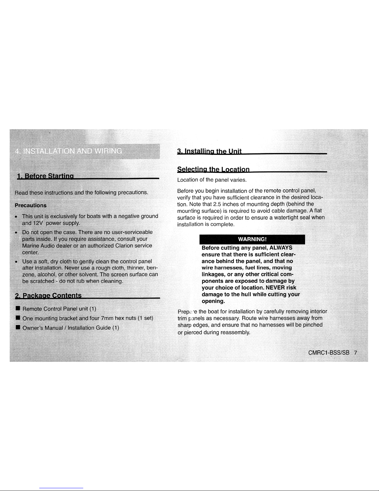
Before you begin installation of the rern
verify that you have sufficient
clearanceint
tion. Note that 2.5 inches of mounting dept
rnounting surface) is required to avoid ca
surface is required
in
order to ensure a
installation is complete.
Before cutting any panel, A
ensurethat there
is
sufficie
ance behind
the
panel, a
wire harnesses, fuel lin
linkages,
or
any other c
ponents are exposed t
your
choiceoflocatio
damage
to
the
hull
whi
opening.
'::-e
the boat for installation by ca
anels as necessary. Route .
edges, and ensure that no
reed
during reassernbly.
Page 8

4.
Insert
the
remote control panel
into
that the
gasket
behind
the
remote
completely
against the mounting surface.
5.
Position the bracket onto the rear
of
the remote control pariel,
sliding the two threadedstuds on
the
rearotthepanel
through
the two holes in the mounting
bracket{as
shownbel0-.v)
.1"i~ht"
en the 7mm hex
nuts
onto the bracket,
again
ensuring
that
the
gasket seals tightly to the front of the mounting surface.
AvOii:!
pinching the cable.
Mounting Bracket
JI~!!lr~II~~~~\~!~'~I~~!"~8,untirn.~kl~alion
is
aflat
surface
with
suf-
~TfC:!lnp~
t;~~;"'Jcma
access.
Ensure that
the
~~ll~ei$u,bd«:!~SlfUIIY
completed before con-
v,
.,,"""""'"
a 24' extension is
1
!10!flllll~~I!ii!:lilll~1!~E~~~~~with
"break
lines'
to
allow
thi{'knIA~<::~Ac:.
Determine
if
the
and remove the appropriate
a pair of pliers. Each
Page 9

Connect a wire to one of
the mounting studs
on
the
rear of the unit, using a #8
ring terminal (not supplied).
Connect this wire to the
boat's negative (-) ground.
Wiring Connections
• Disconnect the negative battery terminal before making any
wiring connections.
• Be particularly careful where you route wires and cables.Keepthe:rn,
away from the engine, exhaust system, etc, Heat may damage wires.
• Sharp edges can pierce wire insulation and cablejackets
,
cau$il'1g
short circuits, damage to the craft, blown fuses, and system failure.
If
any fuse should blow, make sure all connections
are
correct and
no
wires are damaged before replacing the fuse. Always use fuses
that are the same amperage value
astheoriginal.Wh~nreplacing
a fuse, never let the battery side touch any
metal part or any other wire.
Wiring
1. Connecting the ground lead.
ote control
rear
of
the
bracket (as
bracket
htly to the
cable.
~W~i1
>
"
of
the rem
Sl'
JS
on the
.",'
It:::,
IIIVUllLlIl~
nuts into
f
........
''"'
seals tig
'.',.,
th
III
VlllvUIII~
e
,;"
'"
..
';
'"
"
; .i
,',.'.
;",
,;,
;'.
III
.
tl
,';
;
•
".
~-
-
ii,
..
J:.
,."
"-
"'"
s
"'"
';
.......
"
.......
~
.'
,
e.,'
",
'.,
Page 10

3. Connecting the cables.
Connect
the
DIN cable
fro,nm~;t~h:~e~~i~l:J6~8r~~I\1
to the
rerno1:e(~;).
c
CMD4
or
M455
Page 11
6.
Product must be shipped in it
fully insured, with shipping
any responsibility for any
I
7.
ALL IMPLIED WARRANTI
ITED BY APPLICABLE L
TION THAN THE WARRA
UNDER NO CIRCUMSTAN
ANY LOSS OR DAMAGE,
ING
OUTOFTHE USE OR
BECAUSE SOME STATES
HOW LONG AN IMPLIED
OR LIMITATIONS
OF
INCI
AGES, THE ABOVE LIMI
APPLY TO YOU.
8. THIS LIMITED WARRANT
RIGHTS, AND YOU MAY A
VARY FROM STATE TO
9.
Should you have any diffic
during the warranty period,
clarion.com) for a listin
your area. You may als
In
USA:
Clarion Corporation
of
Attn: Customer Service
661W.Redondo Beac
Gardena, CA.
902
1-800-GO-
(310) 327-910
www.c1arion.co
Page 12

Page 13

CIRRC'-SB
WATERTIGHT
MARINE
DISPLAY
REMOTE
CONTROL
~
Meets
ASTM
B117
Salt/Fog
Exposure
Standard
~
Meets
ASTM
04329UVExposure
Standard
~
Ignition
Protection
Certified
~
High
Definition
Positive
LCD
Display
~
Bright
White
LED
Illumination
~
Rubber
Tactile
Action
Control
Buttons
~
Multi-Remote
Compatible
~
Compatible
with
Clarion
Marine
CMD4,
M455,
and
XMD3
Source
Units
 Loading...