

Page 1

VARIANT 260/280
Technical Systems
Hydraulic System
Page 2

Hydraulic System VARIANT 260/280 TIC
2 var-h 11/04
Page 3

TIC VARIANT 260/280 Hydraulic System
Hydraulic system
Contents
Chapter 1 Overall hydraulic system circuit diagram.............................5
Chapter 2 Function .................................................................................15
Chapter 3 Valve components.................................................................29
Index.........................................................................................................57
11/04 var-h 3
Page 4

Hydraulic System VARIANT 260/280 TIC
4 var-h 11/04
Page 5

TIC VARIANT 260/280 Hydraulic System
Chapter 1 Overall hydraulic system circuit diagram
1.1
Circuit diagram – without active hydraulic system.............................6
1.2
Circuit diagram – with active hydraulic system,
1.3
Circuit diagram – with active hydraulic system,
with integrated pressure holding valve (754) up to serial no. … .....10
without integrated pressure holding valve (754) from serial no. .....12
11/04 var-h 5
Page 6
Hydraulic System VARIANT 260/280 TIC
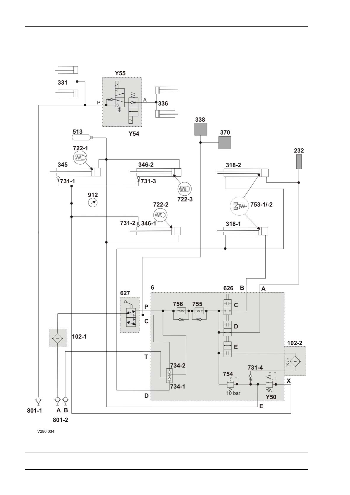
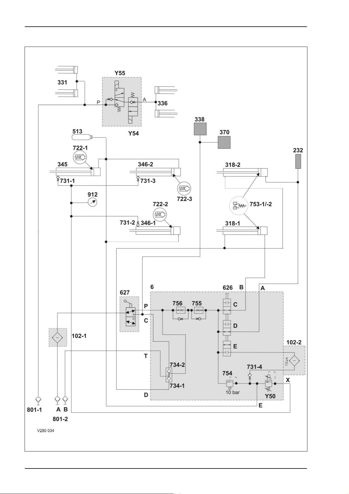
1.1 Circuit diagram – without active hydraulic system
6 var-h 11/04
Page 7

TIC VARIANT 260/280 Hydraulic System
Key to diagram:
6 Valve block
102-1 Filter (option)
When factory-mounted, filter (102-2) is not provided
- in this case, a hydraulic loop line is installed here.
In case of retrofits, filter (102-2) remains in place.
102-2 Filter (series equipment)
232 Lubricating oil pump
is actuated when building up pressure for opening the tailgate.
318-1 Left side tailgate hydraulic cylinder
318-2 Right side tailgate hydraulic cylinder
331 Pick-up raise/lower hydraulic cylinders
2 pieces, spring-loaded
336 Knife support On/Off hydraulic cylinder
338 Rotor cut-out clutch
345 Top tensioning arm hydraulic cylinder
346-1 Bottom left tensioning arm hydraulic cylinder
346-2 Bottom right tensioning arm hydraulic cylinder
370 Drive clutch for roller no. 3. When subject to pressure, the clutch opens so that roller no. 3 does
not drive the belts (when opening the tailgate).
513 Hydraulic accumulator
pressurised to 2 bar
626-C Shut-off tap
for left-side tailgate cylinder. Is combined with 626-D and 626-E.
626-D Shut-off tap
626-E Shut-off tap
627 Shut-off tap
for right-side tailgate cylinder. Is combined with 626-C and 626-E.
for belt tensioner cylinder. Is combined with 626-B and 626-C.
- blocked when 626-C and 626-D are open.
- open when 626-C and 626-D are blocked.
In the initial position (see circuit diagram):
- the oil supply to valve block (6), (input P) is ensured.
- the oil supply to the rotor cut-out clutch (338) is shut off.
When actuated:
- the oil supply to the valve block (6), (input P), is shut off
- the oil supply to the rotor cut-out clutch is provided.
11/04 var-h 7
Page 8

Hydraulic System VARIANT 260/280 TIC
722-1 Anti-cavitation valve
opening pressure 3.6 bar
722-2 Anti-cavitation valve
opening pressure 3.6 bar
722-3 Anti-cavitation valve
opening pressure 3.6 bar
731-1 Non-return valve
731-2 Non-return valve
731-3 Non-return valve
731-4 Non-return valve
shuts off the pre-pressurizing circuit against the filter circuit.
734-1
734-2
753-1
753-2
754 Pressure relief valve
755 Flow controller
756 Flow controller
801-1 Quick release coupling
801-2 Quick release couplings
912 Baling pressure gauge
Y50 Baling pressure build-up solenoid valve
Y54 ROTOCUT knives OUT solenoid valve
Y55 ROTOCUT knives IN solenoid valve
Non-return valves lock-up valve unit
shut off the tailgate cylinders (318), the rotor cut-out clutch (338) and the drive clutch (370).
Pressure relief valve
limits the pressure in the rod spaces to 250 bar.
maintains the pressure in the tensioning arm circuit at 10 bar.
controls the volume flow for opening the tailgate to 50 l/min. The non-return valve does actually not
exist – here it serves merely for better understanding of the circuit diagram.
controls the volume flow for closing the tailgate to 18 l/min. The non-return valve does actually not
exist – here it serves merely for better understanding of the circuit diagram.
single-acting control unit. Oil supply for knife support and pick-up.
double-acting control unit Open / close tailgate oil supply.
- limits the pressure in the tensioning arm circuit and thus controls the baling pressure.
- is controlled by the electronic box (the desired baling pressure is set by a potentiometer).
- when the power supply fails, the highest baling pressure is reached.
8 var-h 11/04
Page 9

TIC VARIANT 260/280 Hydraulic System
Notes:
11/04 var-h 9
Page 10
Hydraulic System VARIANT 260/280 TIC
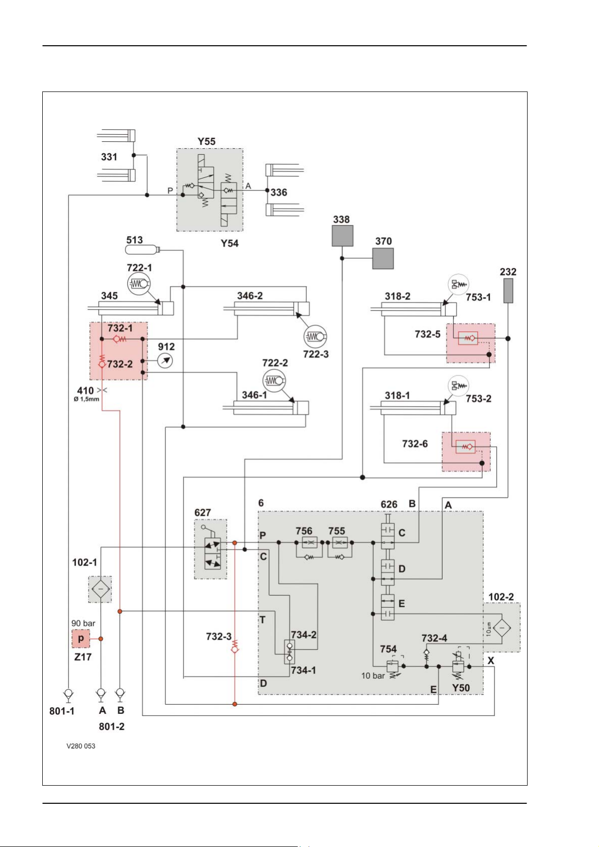
1.2 Circuit diagram – with active hydraulic system, with integrated pressure holding valve (754)
up to serial no. …
10 var-h 11/04
Page 11

TIC VARIANT 260/280 Hydraulic System
Key to diagram:
6 Valve block
102-1 Filter (option)
102-2 Filter
232 Lubricating oil pump
318-1 Tailgate left hydraulic cylinder
318-2 Tailgate right hydraulic cylinder
331 Pick-up hydraulic cylinder
336 Knife support hydraulic cylinder
338 Rotor cut-out clutch
345 Top right tensioning arm hydraulic cylinder
346-1 Bottom left tensioning arm hydraulic cylinder
346-2 Bottom right tensioning arm hydraulic cylinder
370 Roller 3 drive clutch
410 Orifice plate diam. 1.5 mm (for oil flow limiting)
513 Hydraulic accumulator (pressurised to 2 bar)
626-C Shut-off tap
626-D Shut-off tap
626-E Shut-off tap
627 Shut-off tap
722-1 Anti-cavitation valve (open pressure 3.6 bar)
722-2 Anti-cavitation valve (open pressure 3.6 bar)
722-3 Anti-cavitation valve (open pressure 3.6 bar)
732-1 Non-return valve
732-2 Non-return valve
732-3 Non-return valve
732-4 Non-return valve
732-5 Non-return valve
732-6 Non-return valve
734-1 Lock-up valve unit (non-return valve)
734-2 Lock-up valve unit (non-return valve)
753-1, -2 Pressure relief valve 250 bar
754 Pressure holding valve is blocked = no function
755 Flow controller
756 Flow controller
801-1 Quick release coupling
(single-acting additional control unit on tractor)
801-2 Quick release couplings
(double-acting additional control unit on tractor)
912 Baling pressure gauge
Y50 Baling pressure solenoid valve
Y54 2/3 way valve, knife support out
Y55 2/3 way valve, knife support in
Z17 Pressure switch (90 bar)
11/04 var-h 11
Page 12
Hydraulic System VARIANT 260/280 TIC
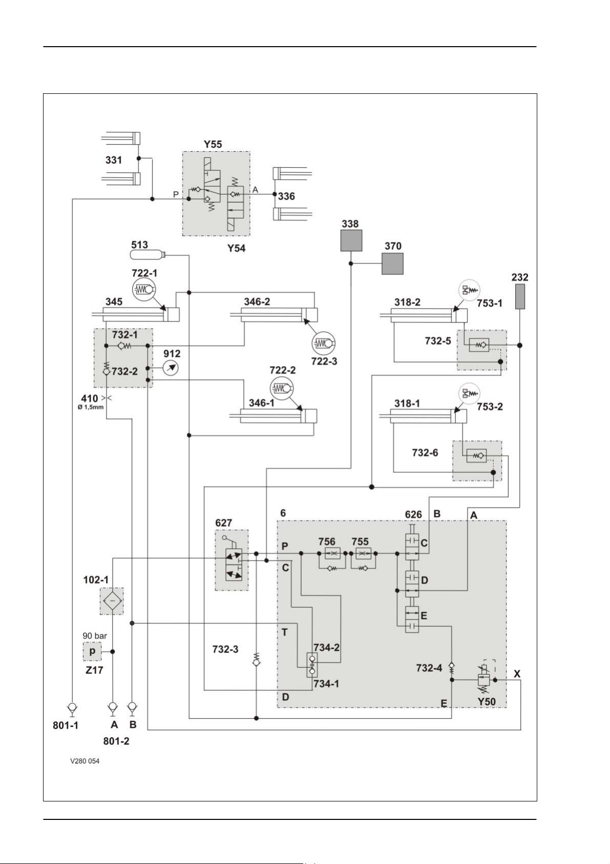
1.3 Circuit diagram – with active hydraulic system, without integrated pressure holding valve (754)
from serial no. ...
12 var-h 11/04
Page 13

TIC VARIANT 260/280 Hydraulic System
Key to diagram:
6 Valve block
102-1 Filter (option)
102-2 Filter
232 Lubricating oil pump
318-1 Tailgate left hydraulic cylinder
318-2 Tailgate right hydraulic cylinder
331 Pick-up hydraulic cylinder
336 Knife support hydraulic cylinder
338 Rotor cut-out clutch
345 Top right tensioning arm hydraulic cylinder
346-1 Bottom left tensioning arm hydraulic cylinder
346-2 Bottom right tensioning arm hydraulic cylinder
370 Roller 3 drive clutch
410 Orifice plate diam. 1.5 mm (for oil flow limiting)
513 Hydraulic accumulator (pressurised to 2 bar)
626-C Shut-off tap
626-D Shut-off tap
626-E Shut-off tap
627 Shut-off tap
722-1 Anti-cavitation valve (open pressure 3.6 bar)
722-2 Anti-cavitation valve (open pressure 3.6 bar)
722-3 Anti-cavitation valve (open pressure 3.6 bar)
732-1 Non-return valve
732-2 Non-return valve
732-3 Non-return valve
732-4 Non-return valve
732-5 Non-return valve
732-6 Non-return valve
734-1 Lock-up valve unit (non-return valve)
734-2 Lock-up valve unit (non-return valve)
753-1, -2 Pressure relief valve 250 bar
755 Flow controller
756 Flow controller
801-1 Quick release coupling
(single-acting additional control unit on tractor)
801-2 Quick release couplings
(double-acting additional control unit on tractor)
912 Baling pressure gauge
Y50 Baling pressure solenoid valve
Y54 2/3 way valve, knife support out
Y55 2/3 way valve, knife support in
Z17 Pressure switch (90 bar)
11/04 var-h 13
Page 14

Hydraulic System VARIANT 260/280 TIC
14 var-h 11/04
Page 15

TIC VARIANT 260/280 Hydraulic System
Chapter 2 Function
2.1
Function – without active hydraulic system .....................................16
Function – with active hydraulic system,
2.2
Function – with active hydraulic system,
2.3
with integrated pressure holding valve (754) up to serial no. ... ......20
without integrated pressure holding valve (754) from serial no.......24
11/04 var-h 15
Page 16
Hydraulic System VARIANT 260/280 TIC
2.1 Function – without active hydraulic system
16 var-h 11/04
Page 17

TIC VARIANT 260/280 Hydraulic System
Description of function:
Close tailgate Volume flow enters the valve block (6, port T) via port (801-2 B) and flows
to the lock-up valve unit non-return valve (734-1). The lock-up valve unit
is opened.
Pressurized oil flows into the rod spaces of hydraulic cylinders (318-1 and
318-2) via the opened lock-up valve unit non-return valve (734-1) and
port D.
The volume flow displaced from the ram spaces of hydraulic cylinders
(318-1 and 318-2) flows into the tank via the shut-off taps (626 C and D),
the flow controllers (756 and 755), the shut-off tap (627) and filter (102-1).
The flow controller controls the returning volume flow to 18 l/min., making
the tailgate closing velocity lower than the opening velocity.
Baling Baled material pulls the hydraulic cylinders (346-1, 346-2 and 345) to the
outside by means of the tensioning arms. This builds up baling pressure
in the rod spaces of these cylinders.
The pressure can be read on pressure gauge (912 baling pressure).
The baling pressure enters valve block (6) via input (X).
The baling pressure is applied at the baling pressure build-up solenoid
valve (Y50).
When the set baling pressure has been reached, the baling pressure
build-up solenoid valve (Y50) opens, making volume flow flow via port (E)
into the ram sides of hydraulic cylinders (346-1, 346-2 and 345).
The hydraulic accumulator (513) compensates the volumetric difference.
Open tailgate Volume flow flows into valve block 6 (port P) via port (801-2 A), filter
(102-1) and the rotor clutch / 2
nd
belt drive shut-off tap (627).
The volume flow flows via the open shut-off taps (626C and 626D) into
the ram spaces of hydraulic cylinders (318-1 and 318-2), via ports (A and
B). During this process, the flow rate is regulated to 50 l/min. by the flow
controllers (756 and 755).
At the same time, the lubricating oil pump (232) is supplied.
Pressurized oil is tapped directly downstream of inlet (P) of valve block (6)
which opens the lock-up valve unit non-return valve (734-1).
The volume flow displaced from the rod spaces of hydraulic cylinders
(318-1 and 318-2) flows through the open lock-up valve unit non-return
valve (734-1) and port (T) to the quick release coupling (801-2 B).
Downstream of the rotor clutch / 2nd belt drive shut-off tap (627),
pressurized oil flows to the rotor cut-out clutch (338) and to the drive
clutch (370) for roller 3.
The clutches open so that the rotor and the drive of roller 3 are switched
off while the tailgate is opened.
11/04 var-h 17
Page 18

Hydraulic System VARIANT 260/280 TIC
r
Relieving the belts during
maintenance work in the
baling chamber
Tensioning the belts The baling chamber service shut-off valve still is in the "Tailgate blocked"
Swinging in the knife
When actuating the "Swing in knife support" button, the 2/3 way
support
- Switch on control box (baler CCT) so the baling pressure build-up
solenoid valve (Y50) is energized.
- Disengage the p.t.o. shaft.
- Open the tailgate as far as necessary and secure it.
- Actuate the baling chamber service shut-off valve (626):
The shut-off taps (626 C) and (626 D) of the tailgate are now shut off and
the shut-off tap (626 E) is open.
Oil flows into valve block 6 (port P) via port (801-2 A), filter (102-1) and
the rotor clutch / 2
nd
belt drive shut-off tap (627).
Volume flow continues to flow via filter (102-2), non-return valve (731-4)
and port (E) into the ram spaces of hydraulic cylinders (346-1, 346-2 and
345) through the open shut-off tap (626 E).
The cylinders extend and the belts are relieved.
The volume flow displaced from the rod spaces of hydraulic cylinders
(346-1, 346-2 and 345) flows to the baling pressure build-up solenoid
valve (Y50) via port (X). This valve is electronically regulated to 0 bar
when the tailgate is open and oil may therefore flow freely through it.
The rod spaces and the ram spaces of the belt tensioner cylinders (346-1,
346-2 and 345) are now connected with each other.
There is the same pressure in both cylinder spaces, but since the greater
force is generated on the ram surface (greater by the force of the rod
surface), the cylinders extend and relieve the belts.
position; now the double-acting control unit provided on the tractor is set
to the "Lower" position
The hydraulic cylinders (346-1, 346-2 and 345) are retracted by springs
on the left baler side.
The volume flow displaced from the ram spaces flows via port (E) and
uses two different paths, depending on the pressure:
- when the pressure is above 10 bar, it flows into the tank via the
pressure relief valve (754), the flow controllers (756 and 755), port
(P) and port (801-2 A).
- when the pressure is below 10 bar, the non-return valves (722-1,
722-2 and 722-3) open and provide volumetric compensation so that
the tensioning arms can return to their initial position faster.
When maintenance work is finished, the tailgate is closed; during this, the
belts must be driven so that they will not be squeezed.
directional control valve (Y55) "ROTOCUT knives IN" is energized.
Volume flow flows into the ROTOCUT knives hydraulic cylinders (336) via
port (801-1) and the energized 2/3 way valve.
The ROTOCUT knives hydraulic cylinders (336) extend and swing in the
knife support.
The extended ROTOCUT knives hydraulic cylinders (336) are kept in thei
position by the non-return valve inside the 2/3 directional control valve
(Y54).
18 var-h 11/04
Page 19

TIC VARIANT 260/280 Hydraulic System
Swinging out the knife
support
The single-acting tractor control unit is set to the "Lower" position – port
(801-1) is connected to the tank.
When actuating the "Swing out knife support" button, the 2/3 way
directional control valve (Y54) is energized.
The baled material loads the ROTOCUT knives hydraulic cylinders (336),
making volume flow flow into the tank from the ram spaces via the
energized 2/3 way valve (Y54), the unenergized 2/3 way valve (Y55) and
port (801-1).
11/04 var-h 19
Page 20

Hydraulic System VARIANT 260/280 TIC
2.2 Function – with active hydraulic system, with integrated pressure holding valve (754)
up to serial no. ...
20 var-h 11/04
Page 21

TIC VARIANT 260/280 Hydraulic System
Description of function:
Closing the tailgate –
without active pressure
control
Oil enters the valve block (6, port T) via port (801-2 B) and opens the
lock-up valve unit non-return valve (734-1).
Via port D, the pressurized oil flows to the non-return valves (732-5 and
732-6) which are unlocked. The pressurized oil flows on into the rod
spaces of hydraulic cylinders (318-1 and 318-2). The tailgate is closed.
The oil displaced from the ram spaces of hydraulic cylinders (318-1 and
318-2) flows via the unblocked non-return valves (732-5 and 732-6), the
shut-off taps (626 C and 626 D), the flow controllers (755 and 756), the
shut-off tap (627) and filter (102-1) into the tank.
The flow controllers (755 und 756) regulate the oil flow to 18 l/min. which
reduces the closing time of the tailgate as compared with the opening
time.
Closing the tailgate – with
active pressure control
1. The pilot-controlled non-return valves (732-5 and 732-6) reliably seal
off the tailgate cylinders. This is particularly important when
performing service work while the tailgate is open. The tailgate can be
closed only by building up pressure in port (801-2 B).
2. Via port (801-2 B), oil also flows into the rod spaces of hydraulic
cylinders (345, 346-1 and 346-2) in order to retract the hydraulic
cylinders quickly – the belts are tensioned. To this end, the non-return
valves (732-1 and 732-2) are opened by the oil flow.
The oil is applied at port X of the Baling pressure build-up solenoid
valve (Y55) which is electronically regulated to 90 bar during the
tailgate closing process.
The oil displaced from the ram spaces of hydraulic cylinders
(345, 346-1 and 346-2) is drained via the non-return valve (732-3), the
shut-off tap (627) and port A. The pressure relief valve (754) is
mechanically blocked = no function.
Baling Baled material pulls the hydraulic cylinders (346-1, 346-2 and 345) to the
outside by means of the tensioning arms. Baling pressure is thus built up
in the rod spaces of these cylinders; this pressure can be read at
pressure gauge (912).
The baling pressure enters valve block (6) at inlet (X) and is applied to the
Baling pressure build-up valve (Y50).
When the set baling pressure has been reached, the Baling pressure
build-up solenoid valve (Y50) opens, making oil flow via port (E) into the
ram sides of hydraulic cylinders (346-1, 346-2 and 345).
The hydraulic accumulator (513) compensates the volumetric difference
between the cylinder sides.
11/04 var-h 21
Page 22

Hydraulic System VARIANT 260/280 TIC
A
Opening the tailgate –
without active pressure
control
Opening the tailgate – with
active pressure control
Relieving the belts
(for maintenance work in
the baling chamber)
Oil flows into valve block 6 (port P) via port (801-2 A), filter (102-1) and
the rotor clutch / 2
nd
belt drive shut-off tap (627).
Oil flows via the open shut-off taps (626C and 626D) into the ram spaces
of hydraulic cylinders (318-1 and 318-2), via ports (A and B) and the nonreturn valves (732-5 and 732-6).
During this process, the flow rate is regulated to 50 l/min. by the flow
controllers (756 and 755).
At the same time, the lubricating oil pump (232) is supplied. Pressurized
oil is tapped directly downstream of inlet (P) of valve block (6) which
opens the lock-up valve unit non-return valve (734-1) via a ram.
The oil displaced from the rod spaces of hydraulic cylinders (318-1 and
318-2) flows through the open lock-up valve unit non-return valve (734-1)
and port (T) to the quick release coupling (801-2 B).
Downstream of the rotor clutch / 2nd belt drive shut-off tap (627),
pressurized oil flows to the rotor cut-out clutch (338) and to the drive
clutch (370) for roller 3.
The clutches open so that the rotor and the drive of roller 3 are switched
off while the tailgate is opened.
s early as when opening the tailgate, the pressure rises to above 90 bar.
The pressure switch (Z17) opens. With this signal, the module regulates
the Baling pressure build-up solenoid valve (Y50) to 0 bar. Now the rod
spaces of hydraulic cylinders (345, 346-1 and 346-2) are pressureless
and the belts are relieved – opening the tailgate is accelerated.
1. Switch on control box (baler CCT) so the Baling pressure build-up
solenoid valve (Y50) is energized.
2. Disengage the p.t.o. shaft.
3. Open the tailgate as far as necessary and secure it.
4. Actuate the shut-off valve (626):
The shut-off taps (626 C) and (626 D) of the tailgate are now blocked
and shut-off tap (626 E) is open.
Oil flows into valve block 6 (port P) via port (801-2 A), filter (102-1)
and shut-off tap (627).
Oil continues to flow via filter (102-2), non-return valve (732-4) and
port (E) into the ram spaces of hydraulic cylinders (346-1, 346-2 and
345) through the open shut-off tap (626 E). The cylinders extend and
the belts are relieved.
The oil displaced from the rod spaces of hydraulic cylinders
(346-1, 346-2 and 345) flows to the Baling pressure build-up solenoid
valve (Y50) via port (X). This valve is electronically regulated to 0 bar
when the tailgate is open and oil may therefore flow freely through it.
The rod spaces and the ram spaces of the belt tensioner cylinders
(346-1, 346-2 and 345) are now connected with each other.
There is the same pressure in both cylinder spaces, but since the
greater force is generated on the ram surface, the cylinders extend
and relieve the belts.
22 var-h 11/04
Page 23

TIC VARIANT 260/280 Hydraulic System
r
Tensioning the belts The baling chamber service shut-off valve still is in the "Tailgate blocked"
position; now the double-acting control unit provided on the tractor is set
to the "Lower" position.
The hydraulic cylinders (346-1, 346-2 and 345) are retracted by springs
on the left baler side.
When maintenance work is complete, the tailgate is closed and the belts
must be driven during closing. Otherwise there is a risk of the belts being
squeezed.
- with active pressure
control
Swinging in the knife
support
Swinging out the knife
support
The oil displaced from the ram spaces during this process flows into the
tank via non-return valve (732-3), shut-off tap (627) and port (801-2 A).
The pressure relief valve (754) is mechanically blocked = no function.
When actuating the "Swing in knife support" button, the 2/3 way
directional control valve (Y55) "ROTOCUT knives IN" is energized.
Oil flows into the ROTOCUT knives hydraulic cylinders (336) via port
(801-1) and the energized 2/3 way valve. The ROTOCUT knives hydraulic
cylinders (336) extend and swing in the knife support.
The extended ROTOCUT knives hydraulic cylinders (336) are kept in thei
position by the non-return valve inside the 2/3 directional control valve
(Y54).
The single-acting tractor control unit is set to the "Lower" position – port
(801-1) is connected to the tank. When actuating the "Swing out knife
support" button, the 2/3 way directional control valve (Y54) is energized.
The baled material loads the ROTOCUT knives hydraulic cylinders (336),
making oil flow into the tank from the ram spaces via the energized 2/3
way valve (Y54), the unenergized 2/3 way valve (Y55) and port (801-1).
11/04 var-h 23
Page 24

Hydraulic System VARIANT 260/280 TIC
2.3 Function – with active hydraulic system, without integrated pressure holding valve (754) from serial no.
24 var-h 11/04
Page 25

TIC VARIANT 260/280 Hydraulic System
Description of function:
Closing the tailgate –
without active pressure
control
Oil enters the valve block (6, port T) via port (801-2 B) and opens the
lock-up valve unit non-return valve (734-1).
Via port D, the pressurized oil flows to the non-return valves (732-5 and
732-6) which are unlocked. The pressurized oil flows on into the rod
spaces of hydraulic cylinders (318-1 and 318-2). The tailgate is closed.
The oil displaced from the ram spaces of hydraulic cylinders (318-1 and
318-2) flows via the unblocked non-return valves (732-5 and 732-6), the
shut-off taps (626 C and 626 D), the flow controllers (755 and 756), the
shut-off tap (627) and filter (102-1) into the tank.
The flow controllers (755 and 756) regulate the oil flow to 18 l/min. which
reduces the closing time of the tailgate as compared with the opening
time.
Closing the tailgate – with
active pressure control
1. The pilot-controlled non-return valves (732-5 and 732-6) reliably seal
off the tailgate cylinders. This is particularly important when
performing service work while the tailgate is open. The tailgate can be
closed only by building up pressure in port (801-2 B).
2. Via port (801-2 B), oil also flows into the rod spaces of hydraulic
cylinders (345, 346-1 and 346-2) in order to retract the hydraulic
cylinders quickly – the belts are tensioned. To this end, the non-return
valves (732-1 and 732-2) are opened by the oil flow.
The oil is applied at port X of the Baling pressure build-up solenoid
valve (Y55) which is electronically regulated to 90 bar during the
tailgate closing process.
The oil displaced from the ram spaces of hydraulic cylinders (345,
346-1 and 346-2) is drained via the non-return valve (732-3), the shutoff tap (627) and port A.
Baling Baled material pulls the hydraulic cylinders (346-1, 346-2 and 345) to the
outside by means of the tensioning arms. Baling pressure is thus built up
in the rod spaces of these cylinders; this pressure can be read at
pressure gauge (912).
The baling pressure enters valve block (6) at inlet (X) and is applied to the
Baling pressure build-up valve (Y50).
When the set baling pressure has been reached, the baling pressure
build-up solenoid valve (Y50) opens, making oil flow via port (E) into the
ram sides of hydraulic cylinders (346-1, 346-2 and 345).
The hydraulic accumulator (513) compensates the volumetric difference
between the cylinder sides.
11/04 var-h 25
Page 26

Hydraulic System VARIANT 260/280 TIC
Opening the tailgate –
without active pressure
control
Opening the tailgate – with
active pressure control
Relieving the belts
(for maintenance work in
the baling chamber)
Oil flows into valve block 6 (port P) via port (801-2 A), filter (102-1) and
the rotor clutch / 2
nd
belt drive shut-off tap (627).
Oil flows via the open shut-off taps (626C and 626D) into the ram spaces
of hydraulic cylinders (318-1 and 318-2), via ports (A and B) and the nonreturn valves (732-5 and 732-6).
During this process, the flow rate is regulated to 50 l/min. by the flow
controllers (756 and 755).
At the same time, the lubricating oil pump (232) is supplied. Pressurized
oil is tapped directly downstream of inlet (P) of valve block (6) which
opens the lock-up valve unit non-return valve (734-1) via a ram.
The oil displaced from the rod spaces of hydraulic cylinders (318-1 and
318-2) flows through the open lock-up valve unit non-return valve (734-1)
and port (T) to the quick release coupling (801-2 B).
Downstream of the rotor clutch / 2nd belt drive shut-off tap (627),
pressurized oil flows to the rotor cut-out clutch (338) and to the drive
clutch (370) for roller 3.
The clutches open so that the rotor and the drive of roller 3 are switched
off while the tailgate is opened.
As early as when opening the tailgate, the pressure rises to above 90 bar.
The pressure switch (Z17) opens. With this signal, the module regulates
the Baling pressure build-up solenoid valve (Y50) to 0 bar. Now the rod
spaces of hydraulic cylinders (345, 346-1 and 346-2) are pressureless
and the belts are relieved – opening the tailgate is accelerated.
1. Switch on control box (baler CCT) so the Baling pressure build-up
solenoid valve (Y50) is energized.
2. Disengage the p.t.o. shaft.
3. Open the tailgate as far as necessary and secure it.
4. Actuate the shut-off valve (626):
The shut-off taps (626 C) and (626 D) of the tailgate are now blocked
and shut-off tap (626 E) is open.
Oil flows into valve block 6 (port P) via port (801-2 A), filter (102-1)
and shut-off tap (627).
Oil continues to flow via filter (102-2), non-return valve (732-4) and
port (E) into the ram spaces of hydraulic cylinders (346-1, 346-2 and
345) through the open shut-off tap (626 E). The cylinders extend and
the belts are relieved.
The oil displaced from the rod spaces of hydraulic cylinders
(346-1, 346-2 and 345) flows to the Baling pressure build-up solenoid
valve (Y50) via port (X). This valve is electronically regulated to 0 bar
when the tailgate is open and oil may therefore flow freely through it.
The rod spaces and the ram spaces of the belt tensioner cylinders
(346-1, 346-2 and 345) are now connected with each other.
There is the same pressure in both cylinder spaces, but since the
greater force is generated on the ram surface, the cylinders extend
and relieve the belts.
26 var-h 11/04
Page 27

TIC VARIANT 260/280 Hydraulic System
r
Tensioning the belts The baling chamber service shut-off valve still is in the "Tailgate blocked"
position; now the double-acting control unit provided on the tractor is set
to the "Lower" position.
The hydraulic cylinders (346-1, 346-2 and 345) are retracted by springs
on the left baler side.
When maintenance work is complete, the tailgate is closed and the belts
must be driven during closing. Otherwise there is a risk of the belts being
squeezed.
- with active pressure
control
Swinging in the knife
support
Swinging out the knife
support
The oil displaced from the ram spaces during this process flows into the
tank via non-return valve (732-3), shut-off tap (627) and port (801-2 A).
The pressure relief valve (754) is mechanically blocked = no function.
When actuating the "Swing in knife support" button, the 2/3 way
directional control valve (Y55) "ROTOCUT knives IN" is energized.
Oil flows into the ROTOCUT knives hydraulic cylinders (336) via port
(801-1) and the energized 2/3 way valve. The ROTOCUT knives hydraulic
cylinders (336) extend and swing in the knife support.
The extended ROTOCUT knives hydraulic cylinders (336) are kept in thei
position by the non-return valve inside the 2/3 directional control valve
(Y54).
The single-acting tractor control unit is set to the "Lower" position – port
(801-1) is connected to the tank. When actuating the "Swing out knife
support" button, the 2/3 way directional control valve (Y54) is energized.
The baled material loads the ROTOCUT knives hydraulic cylinders (336),
making oil flow into the tank from the ram spaces via the energized 2/3
way valve (Y54), the unenergized 2/3 way valve (Y55) and port (801-1).
11/04 var-h 27
Page 28

Hydraulic System VARIANT 260/280 TIC
28 var-h 11/04
Page 29

TIC VARIANT 260/280 Hydraulic System
Chapter 3 Valve components
3.1
Main valve block – without active hydraulic system ........................30
3.2
Baling chamber service shut-off valve –
3.3
Lock-up valve unit (734) ..................................................................38
Pressure relief valve (754), baling pressure build-up
3.4
Flow controllers (755, 756) ..............................................................42
3.5
Rotor cut-out clutch..........................................................................44
3.6
3.7
ROTO CUT knife support IN/OUT solenoid valve (Y54/Y55)..........50
Main valve block – with active hydraulic system .............................52
3.8
without active hydraulic system .......................................................34
solenoid valve (Y50) – without active hydraulic system .................40
11/04 var-h 29
Page 30

Hydraulic System VARIANT 260/280 TIC
3.1 Main valve block – without active hydraulic system
Hydraulic circuit diagram
30 var-h 11/04
Page 31

TIC VARIANT 260/280 Hydraulic System
Key to diagram:
6 Valve block
102-2 Filter (series equipment)
626-C Shut-off tap
for left-side tailgate cylinder Is combined with 626-D and 626-E.
626-D Shut-off tap
for right-side tailgate cylinder. Is combined with 626-C and 626-E.
626-E Shut-off tap
for belt tensioner cylinder. Is combined with 626-B and 626-C.
- blocked when 626-C and 626-D are open.
- open when 626-C and 626-D are blocked.
731-4 Non-return valve
734-1
734-2
754 Pressure relief valve
755 Flow controller
756 Flow controller
Y50 Baling pressure build-up solenoid valve
A - X Ports
Lock-up valve unit non-return valve
shuts off the tailgate hydraulic cylinders (318), the rotor cut-out clutch (338) and the drive clutch
(370).
maintains the pressure in the tensioning arm circuit at 10 bar.
controls the volume flow for opening the tailgate to 50 l/min. The non-return valve does actually not
exist – here it serves merely for better understanding of the circuit diagram.
controls the volume flow for closing the tailgate to 18 l/min. The non-return valve does actually not
exist – here it serves merely for better understanding of the circuit diagram.
- limits the pressure in the tensioning arm circuit and thus controls the baling pressure.
- is controlled by the electronic box (the desired baling pressure is set by a potentiometer).
- when the power supply fails, the highest baling pressure is reached.
11/04 var-h 31
Page 32

Hydraulic System VARIANT 260/280 TIC
Ports
32 var-h 11/04
Page 33

TIC VARIANT 260/280 Hydraulic System
Key to diagram:
102-2 Filter (series equipment)
A Port
To the piston top spaces of the tailgate cylinders
A1 Port
To the knife support ON/OFF hydraulic cylinders
B Port
To the piston top space of the tailgate cylinders
C Port
To the rotor cut-out clutch (338) and drive clutch (370)
M Solenoid coil of Baling pressure build-up solenoid valve (Y50)
P Port
Oil supply from tractor
T Port
Tank (return to tractor)
X Port
To the rod spaces of belt tensioner cylinders
Y50 Baling pressure build-up solenoid valve
- limits the pressure in the tensioning arm circuit and thus controls the baling pressure.
- is controlled by the electronic box (the desired baling pressure is set by a potentiometer).
- when the power supply fails, the highest baling pressure is reached.
Y54 ROTOCUT knives OUT solenoid valve
Y55 ROTOCUT knives IN solenoid valve
11/04 var-h 33
Page 34

Hydraulic System VARIANT 260/280 TIC
3.2 Baling chamber service shut-off valve – without active hydraulic system
34 var-h 11/04
Page 35

TIC VARIANT 260/280 Hydraulic System
Key to diagram:
Description of function:
626 Baling chamber service shut-off valve
626-C Left tailgate cylinder shut-off valve
626-D Right tailgate cylinder shut-off valve
626-E Tensioning cylinder shut-off valve
The bale chamber service shut-off valve 626 is a rotary disc valve with the
following valve functions:
626 C for the left tailgate cylinder
626 D for the right tailgate cylinder and
626 E for the belt tensioner cylinders
11/04 var-h 35
Page 36

Hydraulic System VARIANT 260/280 TIC
Hand lever position
36 var-h 11/04
Page 37

TIC VARIANT 260/280 Hydraulic System
Key to diagram:
Description of function:
626 Baling chamber service shut-off valve
I, II Lever positions
Position I:
The shut-off valves (626 C and 626 D) provide a connection to the tailgate
cylinders. The shut-off valve (626 E) has shut off the connection to the
tensioning cylinders.
Position II:
The shut-off valves (626 C and 626 D) have shut off the connection to the
tailgate cylinders. The shut-off valve (626 E) has opened the connection to
the tensioning cylinders.
11/04 var-h 37
Page 38

Hydraulic System VARIANT 260/280 TIC
3.3 Lock-up valve unit (734)
38 var-h 11/04
Page 39

TIC VARIANT 260/280 Hydraulic System
Key to diagram:
Description of function:
Lock-up valve unit
non-return valve (734-1)
Lock-up valve unit
non-return valve (734-2)
Port C Pressurized oil is applied here in case of:
Port D To the rod spaces of tailgate cylinders (318-1 and 318-2). Pressurized oil
Piston K Is moved to the left by pressure build-up in port (P). This opens the lock-up
Port P Oil supply from tractor. Pressurized oil when tailgate is to be opened.
Port T To tractor. Pressurized oil when tailgate is to be closed.
Blocks port (D) = to the rod spaces of tailgate cylinders (318-1 and 318-2).
Blocks port (C) = to the rotor cut-out clutch (338) and the drive clutch
734-1 Lock-up valve unit non-return valve
734-2 Lock-up valve unit non-return valve
C Port
D Port
K Piston
P Port
T Port
(370).
- rotor cut-out clutch (338) and drive clutch (370) are to be shut down
- tailgate is to be opened
when tailgate is to be closed.
valve unit non-return valve (734-1).
11/04 var-h 39
Page 40

Hydraulic System VARIANT 260/280 TIC
3.4 Pressure relief valve (754), Baling pressure build-up solenoid valve (Y50)
– without active hydraulic system
40 var-h 11/04
Page 41

TIC VARIANT 260/280 Hydraulic System
Key to diagram:
Description of function:
Non-return valve (731-4) shuts off the pre-pressurizing circuit against the filter circuit.
Pressure relief valve (754) Maintains the pressure in the tensioning arm circuit at 10 bar.
Port (E) to the ram spaces of the tensioner cylinders.
Solenoid coil (M) Solenoid coil of Baling pressure build-up solenoid valve (Y50)
Baling pressure build-up
solenoid valve (Y50)
102-2 Filter
731-4 Non-return valve
754 Pressure relief valve
E Port
M Solenoid coil
Y50 Baling pressure build-up solenoid valve
- limits the pressure in the tensioning arm circuit and thus controls the
baling pressure.
- Is actuated by the electronic box (the desired baling pressure is set
with a potentiometer).
- When power supply fails, the highest baling pressure is reached.
11/04 var-h 41
Page 42

Hydraulic System VARIANT 260/280 TIC
3.5 Flow controllers (755, 756)
42 var-h 11/04
Page 43

TIC VARIANT 260/280 Hydraulic System
Key to diagram:
Description of function:
Open tailgate:
Close tailgate:
Baling pressure build-up
solenoid valve (Y50)
755 Flow controller
756 Flow controller
M
P, X Port
V Connection
Y50 Baling pressure build-up solenoid valve
- Volume flow enters via port (P) and flows through flow controller
(756) from the spring side; flow controller (756) does not control the
flow.
- Volume flow flows via the connecting channel to the face end of the
flow controller (755).
- The flow controller (755) controls the volume flow to 50 l/min.
- The volume flow flows via port (V) to the rotary disc valve of the shut-
off tap and continues into the piston top spaces of the tailgate
cylinders.
- Volume flow enters via port (V) and flows through flow controller
(755) from the spring side; flow controller (755) does not control the
flow.
- Volume flow flows via the connecting channel to the face end of the
flow controller (756).
- The flow controller (756) controls the volume flow to 18 l/min.
- The volume flow flows to the tractor via port (P).
- limits the pressure in the tensioning arm circuit and thus controls the
baling pressure.
- is controlled by the electronic box (the desired baling pressure is set
by a potentiometer).
- when the power supply fails, the highest baling pressure is reached.
11/04 var-h 43
Page 44

Hydraulic System VARIANT 260/280 TIC
3.6 Rotor cut-out clutch
Shut-off tap (627)
44 var-h 11/04
Page 45

TIC VARIANT 260/280 Hydraulic System
d
Key to diagram:
627 Rotor clutch / 2
n
belt drive shut-off valve
P, P1 Port
KL Connection
Description of function:
Port K Connection to rotor cut-out clutch and drive clutch
Port P Shut-off tap output = P input into control unit (6)
Port P1 Connection to tractor. This port is located on the back side of the shut-off
tap.
11/04 var-h 45
Page 46

Hydraulic System VARIANT 260/280 TIC
Key to diagram:
Description of function:
338 Rotor cut-out clutch
370 Roller 3 drive clutch
R Rotor
When rotor (R) is blocked, the rotor clutch (338) is shut off separately so
that the rotor (R) can be rotated by hand.
46 var-h 11/04
Page 47

TIC VARIANT 260/280 Hydraulic System
Notes:
11/04 var-h 47
Page 48

Hydraulic System VARIANT 260/280 TIC
Design and function
48 var-h 11/04
Page 49

TIC VARIANT 260/280 Hydraulic System
Key to diagram:
1 Friction disc
2 Bolts
3, 4 Sprocket
5 U-plate
6 Bolts
7 Port
8 Pressure spring
9 Sprocket
Description of function:
Friction disc (1) Ensures rotor rotation while clutch is disengaged. This avoids net damage.
Bolts (2) are bolted to the U-shaped sheet metal (5) and connect the sprockets
(3 and 4) when the clutch is closed.
Sprocket (3) Is welded to sprocket (9).
Sprocket (4) Bale chamber drive
U-plate (5)
- The bolts (2) are bolted here
- Is loaded by the pressure springs (8) so that the bolts (2) remain
engaged = clutch engaged.
Bolts (6) Is bolted to the transmission input shaft.
Port (7) Hydraulic connection to the shut-off valve and to the rotor cut-out clutch /
nd
2
belt drive (item 627, see circuit diagram).
Pressure spring (8) 3 pieces distributed around the circumference. They load the U-shaped
sheet metal (5).
Sprocket (9) Pick-up rotor drive
Clutch disengage function Pressurized oil enters via port (7) and acts on the top side of bolt (6).
The U-plate (5) performs a stroke of approx. 12 - 14 mm.
As the bolts (2) are bolted to the U-plate, sprocket (4) is disengaged by
sprocket (9). Sprocket (9) may be freely rotated on the bearing bushing.
Clutch engage function No pressurized oil in port (7). The compression springs (8) press on the
bolts (6) connecting the two sprockets (4 and 9) with one another via the
U-shaped sheet metal (5).
11/04 var-h 49
Page 50

Hydraulic System VARIANT 260/280 TIC
3.7 ROTO CUT knife support IN/OUT solenoid valve (Y54/Y55)
50 var-h 11/04
Page 51

TIC VARIANT 260/280 Hydraulic System
Key to diagram:
Description of function:
Knife support ON Volume flow from the tractor enters via port (P).
Knife support OFF The tractor control unit is set to floating position.
Note: When disassembling or replacing a valve insert, the sealing ring
A ROTO CUT knife support IN/OUT hydraulic cylinder port
P Tractor port (single-acting control unit)
Y54 ROTO CUT knife support OUT solenoid valve
Y55 ROTO CUT knife support IN solenoid valve
The ROTO CUT knife support IN solenoid valve (Y55) is energized.
The pilot spool of the 2/3-way valve opens the ball so the volume flow
flows to the 2/3-way valve (Y54).
The ball of the 2/3-way valve (Y54) is opened by pressure build-up.
The volume flow flows via port (A) to the hydraulic cylinders which swing
in the knife support.
The solenoid of the 2/3-way valve (Y54) is actuated.
The pilot spool of the 2/3-way valve (Y54) opens the ball. Since the knife
support hydraulic cylinders are loaded by the baled material, volume
flow flows via port (A) and via the open ball of the 2/3-way valve (Y54) to
the 2/3-way valve (Y55). The volume flow flows via the non-return valve
(V) to port (P) and further to the tractor (tank).
must always be replaced, too.
Rubber-coated aluminium ring for aluminium valve bodies,
copper ring for steel valve bodies.
The rubber-coated aluminium ring cannot be replaced by a
copper ring and vice versa.
11/04 var-h 51
Page 52

Hydraulic System VARIANT 260/280 TIC
3.8 Main valve block – with active hydraulic system
52 var-h 11/04
Page 53

TIC VARIANT 260/280 Hydraulic System
Key to diagram:
626 Shut-off tap
732-4 Non-return valve
734-1 Lock-up valve unit (non-return valve)
734-2 Lock-up valve unit (non-return valve)
755 Flow controller
756 Flow controller
Y50 Baling pressure solenoid valve
A Consumer port
B Consumer port
P Pump port
T Tank port
11/04 var-h 53
Page 54

Hydraulic System VARIANT 260/280 TIC
Description of function:
Closing the tailgate –
without active pressure
control
Oil enters the valve block (6, port T) via port (801-2 B) and opens the
lock-up valve unit non-return valve (734-1).
Via port D, the pressurized oil flows to the non-return valves (732-5 and
732-6) which are unlocked. The pressurized oil flows on into the rod
spaces of hydraulic cylinders (318-1 and 318-2). The tailgate is closed.
The oil displaced from the ram spaces of hydraulic cylinders (318-1 and
318-2) flows via the unblocked non-return valves (732-5 and 732-6), the
shut-off taps (626 C and 626 D), the flow controllers (755 and 756), the
shut-off tap (627) and filter (102-1) into the tank.
The flow controllers (755 and 756) regulate the oil flow to 18 l/min. which
reduces the closing time of the tailgate as compared with the opening
time.
Closing the tailgate – with
active pressure control
1. The pilot-controlled non-return valves (732-5 and 732-6) reliably seal
off the tailgate cylinders. This is particularly important when
performing service work while the tailgate is open. The tailgate can be
closed only by building up pressure in port (801-2 B).
2. Via port (801-2 B), oil also flows into the rod spaces of hydraulic
cylinders (345, 346-1 and 346-2) in order to retract the hydraulic
cylinders quickly – the belts are tensioned. To this end, the non-return
valves (732-1 and 732-2) are opened by the oil flow.
The oil is applied at port X of the Baling pressure build-up solenoid
valve (Y55) which is electronically regulated to 90 bar during the
tailgate closing process.
The oil displaced from the ram spaces of hydraulic cylinders
(345, 346-1 and 346-2) is drained via the non-return valve (732-3), the
shut-off tap (627) and port A.
Baling Baled material pulls the hydraulic cylinders (346-1, 346-2 and 345) to the
outside by means of the tensioning arms. Baling pressure is thus built up
in the rod spaces of these cylinders; this pressure can be read at
pressure gauge (912).
The baling pressure enters valve block (6) at inlet (X) and is applied to the
Baling pressure build-up valve (Y50).
When the set baling pressure has been reached, the Baling pressure
build-up solenoid valve (Y50) opens, making oil flow via port (E) into the
ram sides of hydraulic cylinders (346-1, 346-2 and 345).
The hydraulic accumulator (513) compensates the volumetric difference
between the cylinder sides.
54 var-h 11/04
Page 55

TIC VARIANT 260/280 Hydraulic System
Opening the tailgate –
without active pressure
control
Opening the tailgate – with
active pressure control
Relieving the belts
(for maintenance work in
the baling chamber)
Oil flows into valve block 6 (port P) via port (801-2 A), filter (102-1) and
the rotor clutch / 2
nd
belt drive shut-off tap (627).
Oil flows via the open shut-off taps (626C and 626D) into the ram spaces
of hydraulic cylinders (318-1 and 318-2), via ports (A and B) and the nonreturn valves (732-5 and 732-6).
During this process, the flow rate is regulated to 50 l/min. by the flow
controllers (756 and 755).
At the same time, the lubricating oil pump (232) is supplied. Pressurized
oil is tapped directly downstream of inlet (P) of valve block (6) which
opens the lock-up valve unit non-return valve (734-1) via a ram.
The oil displaced from the rod spaces of hydraulic cylinders (318-1 and
318-2) flows through the open lock-up valve unit non-return valve (734-1)
and port (T) to the quick release coupling (801-2 B).
Downstream of the rotor clutch / 2
nd
belt drive shut-off tap (627),
pressurized oil flows to the rotor cut-out clutch (338) and to the drive
clutch (370) for roller 3.
The clutches open so that the rotor and the drive of roller 3 are switched
off while the tailgate is opened.
As early as when opening the tailgate, the pressure rises to above 90 bar.
The pressure switch (Z17) opens. With this signal, the module regulates
the Baling pressure build-up solenoid valve (Y50) to 0 bar. Now the rod
spaces of hydraulic cylinders (345, 346-1 and 346-2) are pressureless
and the belts are relieved – opening the tailgate is accelerated.
1. Switch on control box (baler CCT) so the Baling pressure build-up
solenoid valve (Y50) is energized.
2. Disengage the p.t.o. shaft.
3. Open the tailgate as far as necessary and secure it.
4. Actuate the shut-off valve (626):
The shut-off taps (626 C) and (626 D) of the tailgate are now blocked
and shut-off tap (626 E) is open.
Oil flows into valve block 6 (port P) via port (801-2 A), filter (102-1)
and shut-off tap (627).
Oil continues to flow via filter (102-2), non-return valve (732-4) and
port (E) into the ram spaces of hydraulic cylinders (346-1, 346-2 and
345) through the open shut-off tap (626 E). The cylinders extend and
the belts are relieved.
The oil displaced from the rod spaces of hydraulic cylinders
(346-1, 346-2 and 345) flows to the Baling pressure build-up solenoid
valve (Y50) via port (X). This valve is electronically regulated to 0 bar
when the tailgate is open and oil may therefore flow freely through it.
The rod spaces and the ram spaces of the belt tensioner cylinders
(346-1, 346-2 and 345) are now connected with each other.
There is the same pressure in both cylinder spaces, but since the
greater force is generated on the ram surface, the cylinders extend
and relieve the belts.
11/04 var-h 55
Page 56

Hydraulic System VARIANT 260/280 TIC
r
Tensioning the belts The baling chamber service shut-off valve still is in the "Tailgate blocked"
position; now the double-acting control unit provided on the tractor is set
to the "Lower" position.
The hydraulic cylinders (346-1, 346-2 and 345) are retracted by springs
on the left baler side.
When maintenance work is complete, the tailgate is closed and the belts
must be driven during closing. Otherwise there is a risk of the belts being
squeezed.
- with active pressure
control
Swinging in the knife
support
Swinging out the knife
support
The oil displaced from the ram spaces during this process flows into the
tank via non-return valve (732-3), shut-off tap (627) and port (801-2 A).
The pressure relief valve (754) is mechanically blocked = no function.
When actuating the "Swing in knife support" button, the 2/3 way
directional control valve (Y55) "ROTOCUT knives IN" is energized.
Oil flows into the ROTOCUT knives hydraulic cylinders (336) via port
(801-1) and the energized 2/3 way valve. The ROTOCUT knives hydraulic
cylinders (336) extend and swing in the knife support.
The extended ROTOCUT knives hydraulic cylinders (336) are kept in thei
position by the non-return valve inside the 2/3 directional control valve
(Y54).
The single-acting tractor control unit is set to the "Lower" position – port
(801-1) is connected to the tank. When actuating the "Swing out knife
support" button, the 2/3 way directional control valve (Y54) is energized.
The baled material loads the ROTOCUT knives hydraulic cylinders (336),
making oil flow into the tank from the ram spaces via the energized 2/3
way valve (Y54), the unenergized 2/3 way valve (Y55) and port (801-1).
56 var-h 11/04
Page 57

Index
Page 58

Hydraulic System VARIANT 260/280 TIC
Index:
Active hydraulic system 10, 12, 20, 24, 53
A
Bale chamber 35
B
Baling pressure build-up 40
Circuit diagram 5, 6, 10, 12
C
Contents 3
Design 48
D
Flow controller 42
F
Function 15, 16, 20, 24, 48
Hand lever 36
H
Knife support 50
K
Lock-up valve unit 38
L
Main valve block 30, 53
M
Overall hydraulic system 5
L
Ports 33
P
Pressure relief valve 40
ROTO CUT 50
R
Rotor cut-out clutch 44
Shut-off tap 44
S
Shut-off valve 35
Valve components 29
V
58 var-h 11/04
Page 59

At CLAAS KGaA mbH we are constantly improving
our products to reflect the latest technological developments. For this reason, we may from time to time need
to make changes to diagrams and descriptions in this
documentation which do not reflect products which
have already been delivered and which will not be
implemented on these machines.
Technical data, dimensions and weights are given
as an indication only. Responsibility for errors or
omissions not accepted.
Reproduction or translation of this publication, in
whole or part, is not permitted without the written
consent of the CLAAS KGaA mbH.
All rights under the provision of the Copyright Act
are reserved.
CLAAS KGaA mbH
33426 Harsewinkel
Germany
Our contribution to the environment:
CLAAS have printed this manual
on 100 % chlorine free paper.
Page 60

CLAAS KGaA mbH
Postfach 1163
33426 Harsewinkel
Tel. +49 (0)5247 12-0
www.claas.com
0299 256.1
SYS-HY VARIANT 260/280
EN - 03.05 - NF
Printed in Germany
 Loading...