

Page 1

UNIWRAP
Technical Systems
Hydraulic System
Page 2

Page 3

TIC UNIWRAP Hydraulic System
Contents
1 Hydraulic circuit diagram................................................5
2 Pre-conditions for use ................................................... 27
3 Valve block .....................................................................31
4 Individual components .................................................. 41
11/04 UNI-h 3
Page 4

Hydraulic System UNIWRAP TIC
4 UNI-h 11/04
Page 5

TIC UNIWRAP Hydraulic System
1
Hydraulic circuit diagram
1.1 Hydraulic circuit diagram up to serial no.: 72600130 ........................8
1.2 Hydraulic circuit diagram from machine no.: 72600131,
with tipping cradle service shut-off valve (631) ...............................12
1.3 Hydraulic circuit diagram from machine no.: 72600531,
with film clamping cutters flow divider (769)....................................16
1.4 Hydraulic circuit diagram from serial no.: 72601047,
with valve combination (630, 706, 769),
without 3-stage restrictor (645) .......................................................20
1.5 Hydraulic circuit diagram from serial no.: 72601047,
with valve combination (630, 706, 769),
with 3-stage restrictor (645) ............................................................24
11/04 UNI-h-Kap1 5
Page 6

Hydraulic System UNIWRAP TIC
6 UNI-h-Kap1 11/04
Page 7

- up to serial no.: 72600130
1.1
Hydraulic circuit diagram
Page 8
Hydraulic System UNIWRAP TIC
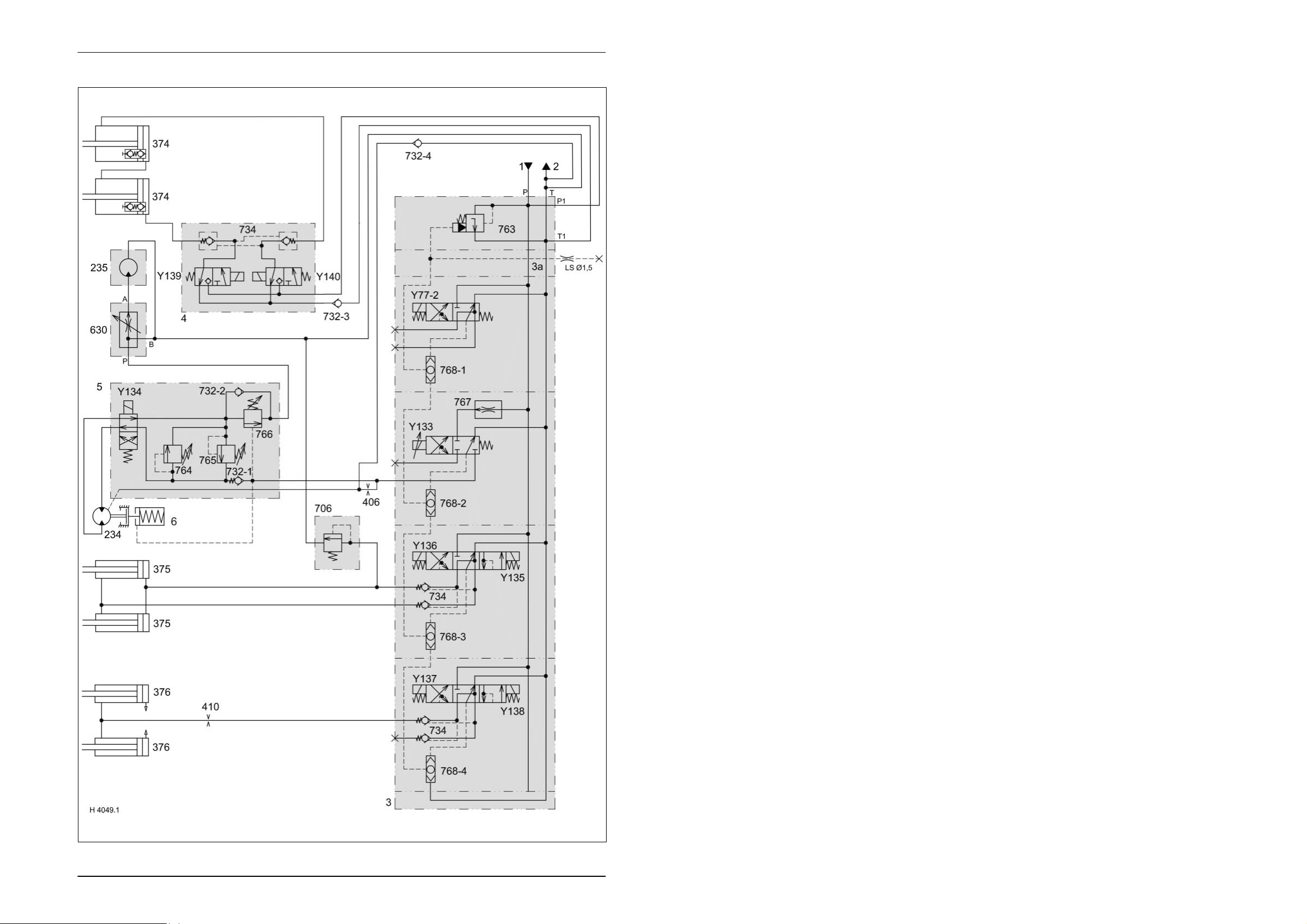
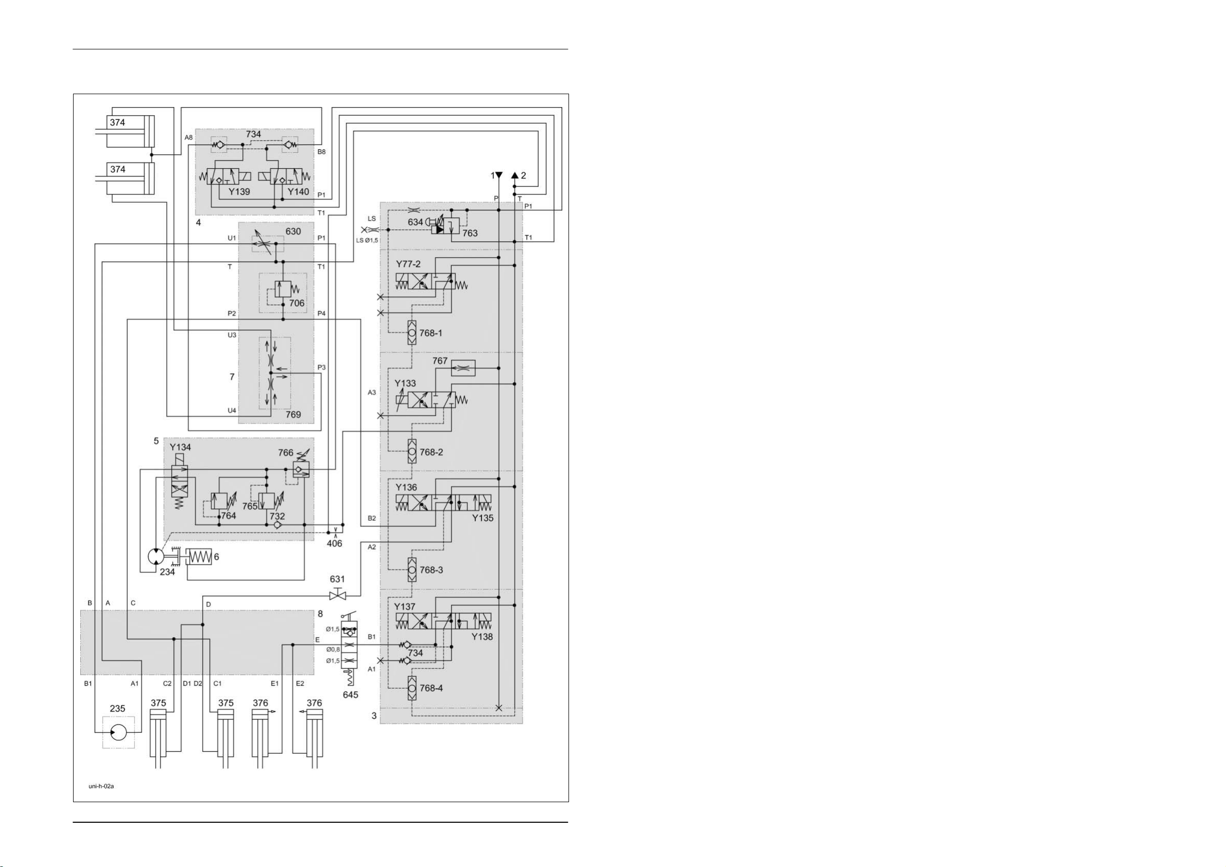
1.1 Hydraulic circuit diagram up to serial no.: 72600130
Key to diagram:
1 Feed line
2 Return line
3 Valve block
3a Plate
4 Valve block
5 Valve block
6 Disc brake
234 Wrapping arm motor
235 Wrapping table motor
374 Film clamping cutters hydraulic cylinder
375 Tipping cradle hydraulic cylinder
376 Wrapping table hydraulic cylinder
406 Orifice plate Ø 0.8 mm
410 Orifice plate Ø 1.5 mm
630 Wrapping table flow control valve
706 Pressure relief valve
732-1 Non-return valve
732-2 Non-return valve
732-3 Non-return valve
732-4 Non-return valve
734 Lock-up valve unit
763 Input pressure balance
764 Pressure relief valve (left) 115
765 Pressure relief valve (right) 115
766 Lower brake valve
767 Wrapping arm motor flow controller
768 LS signal shuttle valves
Y77 Master valve solenoid valve
Y133 Wrapping arm motor forward solenoid valve
Y134 Wrapping arm motor reverse solenoid valve
Y135 Lower tipping cradle solenoid valve
Y136 Raise tipping cradle solenoid valve
Y137 Lower wrapping table solenoid valve
Y138 Raise wrapping table solenoid valve
Y139 Open film cutters solenoid valve
Y140 Close film cutters solenoid valve
+10
+10
bar
bar
8 UNI-h-Kap1 11/04
Page 9

TIC UNIWRAP Hydraulic System
Description of function:
Orifice plate (406)
Ø 0.8 mm
The orifice plate (406) Ø 0.8 mm avoids pressure build-up and
consequently uncontrolled movements of the wrapping arm motor (234).
Wrapping table flow control
valve (630)
The wrapping table flow control valve supplies the hydraulic motor (235)
via output (A).
This volume flow can be adjusted and changes the wrapping table motor /
wrapping arm motor speed ratio and consequently the film layer overlaps.
Pressure relief valve (706) The pressure relief valve limits the pressure to 70 bar when lowering the
tipping cradle hydraulic cylinders.
Non-return valve (732-3) The non-return valve avoids faulty functions of the film clamping cutters
by building up pressure in the T line.
Input pressure balance
(763)
The input pressure balance keeps the connection from P to T open when
no control unit is actuated in valve block 3.
It is closed by LS pressure. The LS pressure is built up when the master
valve (Y77-2) or a control unit in valve block 3 is actuated.
Pressure relief valve (764) The pressure relief valve limits the oil pressure to the wrapping arm motor
(234) and the wrapping table motor (drive) connected in series to
+10
115
bar.
Pressure relief valve (765) The pressure relief valve limits the oil pressure of the wrapping arm motor
(234) to 115
+10
bar when decelerating.
Lower brake valve (766) The non-return valves 732-1/ 732-2 and the lower brake valve (766)
decelerate the wrapping arm motor (234) hydraulically on both sides if the
wrapping arm forward solenoid valve (Y133) is not energized.
Wrapping arm motor flow
controller (767)
The flow controller keeps the volume flow to the wrapping arm motor
(234) constant.
Maximum wrapping speed (approx. 20 l/min.) with SAM wrapping arm
motor.
Maximum wrapping speed (approx. 31 l/min.) with Danfoss wrapping arm
motor.
LS signal shuttle valves
(768)
When operating the control valves in parallel mode, the shuttle valves
allow sending the highest load pressure to the input pressure balance
(763) in each case.
Master valve solenoid valve
(Y77)
The master valve solenoid valve is actuated automatically when a
hydraulic function is to be carried out on the baler.
Now the pump flow is directed into the LS line so that the pressure that
builds up closes the pressure balance (763).
11/04 UNI-h-Kap1 9
Page 10

Hydraulic System UNIWRAP TIC
Description of function:
Wrapping arm forward
solenoid valve (Y133)
The solenoid valve controls the wrapping arm hydraulic motor.
A wrapping arm motor flow controller 767 is provided in the volume flow
input and keeps the volume flow constant.
When the control unit is activated, this volume flow is pumped to the
hydraulic motor (234) which drives the wrapping arm with 28 ... 30 rpm
max. The flow controller may be accessed via the screw plug at the
bottom of the control unit.
The rotational speed of the wrapping arm of 27 rpm ensures that the
wrapping process is shorter than the time required for producing the bale.
Wrapping arm reverse
solenoid valve (Y134)
The solenoid valve changes the direction of oil flow to the wrapping arm
motor (234) and consequently its sense of rotation.
Lower tipping cradle
The solenoid valve lowers the tipping cradle.
solenoid valve (Y135)
Raise tipping cradle
solenoid valve (Y136)
The solenoid valve raises the tipping cradle. The lock-up valve unit 734
avoids lowering of the raised tipping cradle.
Lower wrapping table
solenoid valve (Y137)
The solenoid valve lowers the wrapping table. The lock-up valve unit 734
in the cylinder line avoids lowering of the loaded wrapping table.
Raise wrapping table
The solenoid valve raises the wrapping table.
solenoid valve (Y138)
Open film cutters solenoid
valve (Y139)
The solenoid valve opens both film cutters.
The wrapping table raise solenoid coil (Y138) is actuated simultaneously
with solenoid coils (Y139). This is necessary in order to build up pressure
in the LS line to make the input pressure balance (763) close.
Close film cutters solenoid
valve (Y140)
The solenoid valve closes both film cutters.
The wrapping table raise solenoid coil (Y138) is actuated simultaneously
with solenoid coils (Y139). This is necessary in order to build up pressure
in the LS line to make the input pressure balance (763) close.
10 UNI-h-Kap1 11/04
Page 11

1.2
Hydraulic circuit diagram
- from machine no.: 72600131
- with tipping cradle service shut-off valve (631)
Page 12
Hydraulic System UNIWRAP TIC
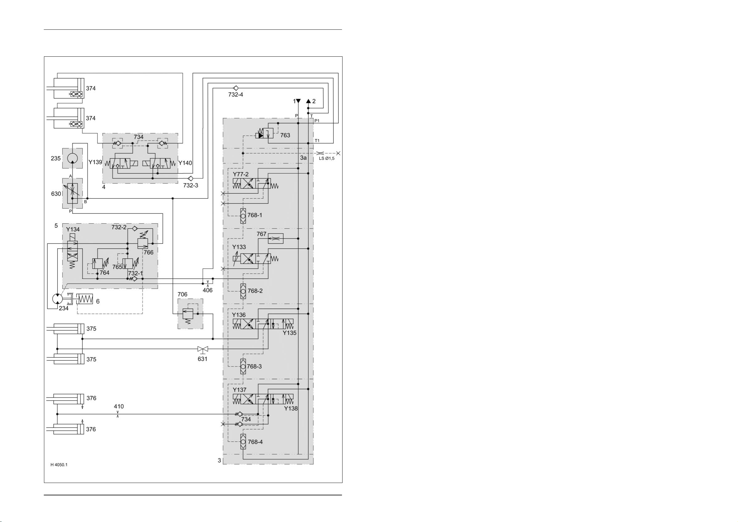
1.2 Hydraulic circuit diagram from machine no.: 72600131,
with tipping cradle service shut-off valve (631)
Key to diagram::
1 Feed line
2 Return line
3 Valve block
3a Plate
4 Clamping cutters valve block
5 Wrapping arm motor valve block
6 Disc brake
234 Wrapping arm motor
235 Wrapping table motor
374 Film clamping cutters hydraulic cylinder
375 Tipping cradle hydraulic cylinder
376 Wrapping table hydraulic cylinder
406 Orifice plate Ø 0.8 mm
410 Orifice plate Ø 1.5 mm
630 Wrapping table flow control valve
631 Tipping cradle shut-off valve
706 Pressure relief valve
732-1 Non-return valve
732-2 Non-return valve
732-3 Non-return valve
732-4 Non-return valve
734 Lock-up valve unit
763 Input pressure balance
764 Pressure relief valve (left) 115
765 Pressure relief valve (right) 115
766 Lower brake valve
767 Wrapping arm motor flow controller
768 LS signal shuttle valves
Y77 Master valve solenoid valve
Y133 Wrapping arm motor forward solenoid valve
Y134 Wrapping arm motor reverse solenoid valve
Y135 Lower tipping cradle solenoid valve
Y136 Raise tipping cradle solenoid valve
Y137 Lower wrapping table solenoid valve
Y138 Raise wrapping table solenoid valve
Y139 Open film cutters solenoid valve
Y140 Close film cutters solenoid valve
+10
+10
bar
bar
12 UNI-h-Kap1 11/04
Page 13

TIC UNIWRAP Hydraulic System
Description of function:
Orifice plate (406)
Ø 0.8 mm
The orifice plate (406) Ø 0.8 mm avoids pressure build-up and
consequently uncontrolled movements of the wrapping arm motor (234).
Wrapping table flow control
valve (630)
The wrapping table flow control valve supplies the hydraulic motor (235)
via output (A).
This volume flow can be adjusted and changes the wrapping table motor /
wrapping arm motor speed ratio and consequently the film layer overlaps.
Tipping cradle shut-off valve
(631)
During service work, the tipping cradle shut-off valve shuts off the oil flow
from the hydraulic cylinders 375.
Pressure relief valve (706) The pressure relief valve limits the pressure to 70 bar when lowering the
tipping cradle hydraulic cylinders.
Non-return valve (732-3) The non-return valve avoids faulty functions of the film clamping cutters
by building up pressure in the T line.
Input pressure balance
(763)
The input pressure balance keeps the connection from P to T open when
no control unit is actuated in valve block 3.
It is closed by LS pressure. The LS pressure is built up when the master
valve (Y77-2) or a control unit in valve block 3 is actuated.
Pressure relief valve (764) The pressure relief valve limits the oil pressure to the wrapping arm motor
(234) and the wrapping table motor (drive) connected in series to
+10
115
bar.
Pressure relief valve (765) The pressure relief valve limits the oil pressure of the wrapping arm motor
(234) to 115
+10
bar when decelerating.
Lower brake valve (766) The non-return valves 732-1/ 732-2 and the lower brake valve (766)
decelerate the wrapping arm motor (234) hydraulically on both sides if the
wrapping arm forward solenoid valve (Y133) is not energized.
Wrapping arm motor flow
controller (767)
The flow controller keeps the volume flow to the wrapping arm motor
(234) constant.
Maximum wrapping speed (approx. 20 l/min.) with SAM wrapping arm
motor.
Maximum wrapping speed (approx. 31 l/min.) with Danfoss wrapping arm
motor.
LS signal shuttle valves
(768)
When operating the control valves in parallel mode, the shuttle valves
allow sending the highest load pressure to the input pressure balance
(763) in each case.
Master valve solenoid valve
(Y77)
The master valve solenoid valve is actuated automatically when a
hydraulic function is to be carried out on the baler.
Now the pump flow is directed into the LS line so that the pressure that
builds up closes the pressure balance (763).
11/04 UNI-h-Kap1 13
Page 14

Hydraulic System UNIWRAP TIC
Description of function:
Wrapping arm forward
solenoid valve (Y133)
The solenoid valve controls the wrapping arm hydraulic motor.
A wrapping arm motor flow controller 767 is provided in the volume flow
input and keeps the volume flow constant.
When the control unit is activated, this volume flow is pumped to the
hydraulic motor (234) which drives the wrapping arm with 28 ... 30 rpm
max. The flow controller may be accessed via the screw plug at the
bottom of the control unit.
The rotational speed of the wrapping arm of 27 rpm ensures that the
wrapping process is shorter than the time required for producing the bale.
Wrapping arm reverse
solenoid valve (Y134)
The solenoid valve changes the direction of oil flow to the wrapping arm
motor (234) and consequently its sense of rotation.
Lower tipping cradle
The solenoid valve lowers the tipping cradle.
solenoid valve (Y135)
Raise tipping cradle
solenoid valve (Y136)
The solenoid valve raises the tipping cradle. The lock-up valve unit 734
avoids lowering of the raised tipping cradle.
Lower wrapping table
solenoid valve (Y137)
The solenoid valve lowers the wrapping table. The lock-up valve unit 734
in the cylinder line avoids lowering of the loaded wrapping table.
Raise wrapping table
The solenoid valve raises the wrapping table.
solenoid valve (Y138)
Open film cutters solenoid
valve (Y139)
The solenoid valve opens both film cutters.
The wrapping table raise solenoid coil (Y138) is actuated simultaneously
with solenoid coils (Y139). This is necessary in order to build up pressure
in the LS line to make the input pressure balance (763) close.
Close film cutters solenoid
valve (Y140)
The solenoid valve closes both film cutters.
The wrapping table raise solenoid coil (Y138) is actuated simultaneously
with solenoid coils (Y139). This is necessary in order to build up pressure
in the LS line to make the input pressure balance (763) close.
14 UNI-h-Kap1 11/04
Page 15

1.3
Hydraulic circuit diagram
- from machine no.: 72600531
- with film clamping cutters flow divider (769)
Page 16
Hydraulic System UNIWRAP TIC
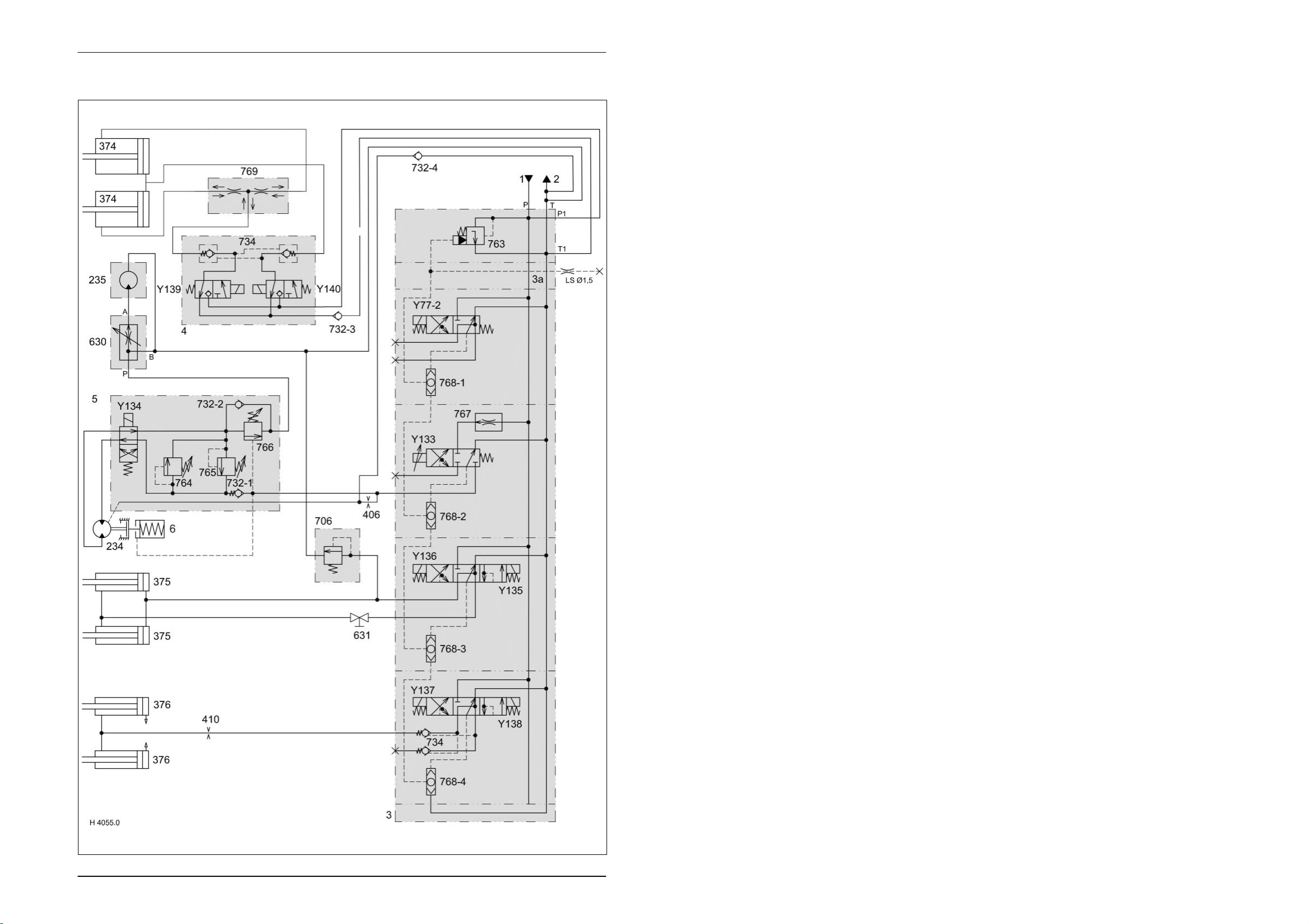
1.3 Hydraulic circuit diagram from machine no.: 72600531,
with film clamping cutters flow divider (769)
Key to diagram:
1 Feed line
2 Return line
3 Valve block
3a Plate
4 Clamping cutters valve block
5 Wrapping arm motor valve block
6 Disc brake
234 Wrapping arm motor
235 Wrapping table motor
374 Film clamping cutters hydraulic cylinder
375 Tipping cradle hydraulic cylinder
376 Wrapping table hydraulic cylinder
406 Orifice plate Ø 0.8 mm
410 Orifice plate Ø 1.5 mm
630 Wrapping table flow control valve
631 Tipping cradle shut-off valve
706 Pressure relief valve
732-1 Non-return valve
732-2 Non-return valve
732-3 Non-return valve
732-4 Non-return valve
734 Lock-up valve unit
763 Input pressure balance
764 Pressure relief valve (left) 115
765 Pressure relief valve (right)
766 Lower brake valve
767 Wrapping arm motor flow controller
768 LS signal shuttle valves
769 Film clamping cutters flow divider
Y77 Master valve solenoid valve
Y133 Wrapping arm motor forward solenoid valve
Y134 Wrapping arm motor reverse solenoid valve
Y135 Lower tipping cradle solenoid valve
Y136 Raise tipping cradle solenoid valve
Y137 Lower wrapping table solenoid valve
Y138 Raise wrapping table solenoid valve
Y139 Open film cutters solenoid valve
Y140 Close film cutters solenoid valve
+10
bar
16 UNI-h-Kap1 11/04
Page 17

TIC UNIWRAP Hydraulic System
Description of function:
Orifice plate (406)
Ø 0.8 mm
The orifice plate (406) Ø 0.8 mm avoids pressure build-up and
consequently uncontrolled movements of the wrapping arm motor (234).
Wrapping table flow control
valve (630)
The wrapping table flow control valve supplies the hydraulic motor (235)
via output (A).
This volume flow can be adjusted and changes the wrapping table motor /
wrapping arm motor speed ratio and consequently the film layer overlaps.
Tipping cradle shut-off valve
(631)
During service work, the tipping cradle shut-off valve shuts off the oil flow
from the hydraulic cylinders 375.
Pressure relief valve (706) The pressure relief valve limits the pressure to 70 bar when lowering the
tipping cradle hydraulic cylinders.
Non-return valve (732-3) The non-return valve avoids faulty functions of the film clamping cutters
by building up pressure in the T line.
Input pressure balance
(763)
The input pressure balance keeps the connection from P to T open when
no control unit is actuated in valve block 3.
It is closed by LS pressure. The LS pressure is built up when the master
valve (Y77-2) or a control unit in valve block 3 is actuated.
Pressure relief valve (764) The pressure relief valve limits the oil pressure to the wrapping arm motor
(234) and the wrapping table motor (drive) connected in series to
+10
115
bar.
Pressure relief valve (765) The pressure relief valve limits the oil pressure of the wrapping arm motor
(234) to 115
+10
bar when decelerating.
Lower brake valve (766) The non-return valves 732-1/ 732-2 and the lower brake valve (766)
decelerate the wrapping arm motor (234) hydraulically on both sides if the
wrapping arm forward solenoid valve (Y133) is not energized.
Wrapping arm motor flow
controller (767)
The flow controller keeps the volume flow to the wrapping arm motor
(234) constant.
Maximum wrapping speed (approx. 20 l/min.) with SAM wrapping arm
motor.
Maximum wrapping speed (approx. 31 l/min.) with Danfoss wrapping arm
motor.
LS signal shuttle valves
(768)
When operating the control valves in parallel mode, the shuttle valves
allow sending the highest load pressure to the input pressure balance
(763) in each case.
Film clamping cutters flow
divider (769)
The flow divider divides the oil flows for opening and closing the film
clamping cutters.
Master valve solenoid valve
(Y77)
The master valve solenoid valve is actuated automatically when a
hydraulic function is to be carried out on the baler.
Now the pump flow is directed into the LS line so that the pressure that
builds up closes the pressure balance (763).
11/04 UNI-h-Kap1 17
Page 18

Hydraulic System UNIWRAP TIC
Description of function:
Wrapping arm forward
solenoid valve (Y133)
The solenoid valve controls the wrapping arm hydraulic motor.
A wrapping arm motor flow controller 767 is provided in the volume flow
input and keeps the volume flow constant.
When the control unit is activated, this volume flow is pumped to the
hydraulic motor (234) which drives the wrapping arm with 28 … 30 rpm
max. The flow controller may be accessed via the screw plug at the
bottom of the control unit.
The rotational speed of the wrapping arm of 27 rpm ensures that the
wrapping process is shorter than the time required for producing the bale.
Wrapping arm reverse
solenoid valve (Y134)
The solenoid valve changes the direction of oil flow to the wrapping arm
motor (234) and consequently its sense of rotation.
Lower tipping cradle
The solenoid valve lowers the tipping cradle.
solenoid valve (Y135)
Raise tipping cradle
solenoid valve (Y136)
The solenoid valve raises the tipping cradle. The lock-up valve unit 734
avoids lowering of the raised tipping cradle.
Lower wrapping table
solenoid valve (Y137)
The solenoid valve lowers the wrapping table. The lock-up valve unit 734
in the cylinder line avoids lowering of the loaded wrapping table.
Raise wrapping table
The solenoid valve raises the wrapping table.
solenoid valve (Y138)
Open film cutters solenoid
valve (Y139)
The solenoid valve opens both film cutters.
The wrapping table raise solenoid coil (Y138) is actuated simultaneously
with solenoid coils (Y139). This is necessary in order to build up pressure
in the LS line to make the input pressure balance (763) close.
Close film cutters solenoid
valve (Y140)
The solenoid valve closes both film cutters.
The wrapping table raise solenoid coil (Y138) is actuated simultaneously
with solenoid coils (Y139). This is necessary in order to build up pressure
in the LS line to make the input pressure balance (763) close.
18 UNI-h-Kap1 11/04
Page 19

1.4
Hydraulic circuit diagram
- from serial no.: 72601047
- with valve combination (630, 706, 769)
- without 3-stage restrictor (645)
Page 20
Hydraulic System UNIWRAP TIC
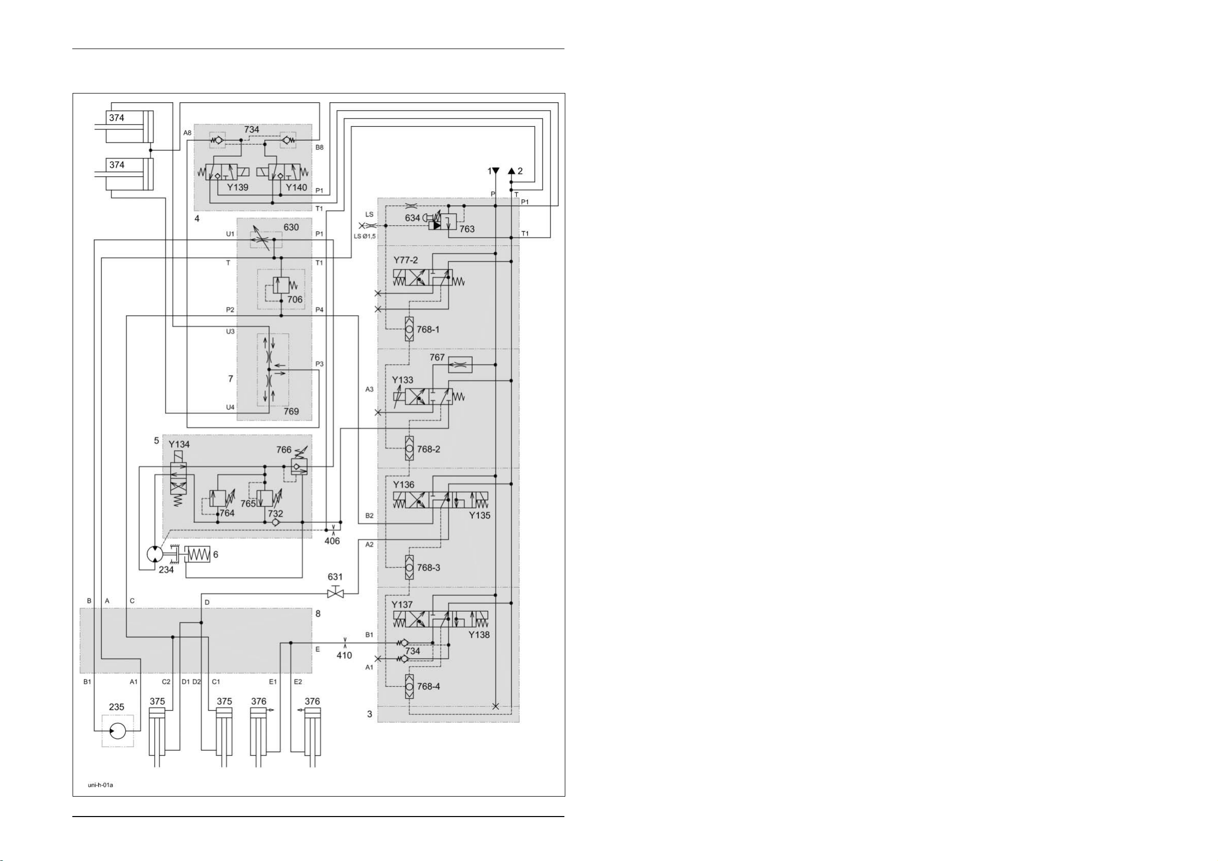
1.4 Hydraulic circuit diagram from serial no.: 72601047, with valve combination (630, 706, 769),
without 3-stage restrictor (645)
Key to diagram:
1 Feed line
2 Return line
3 Valve block
4 Valve block
5 Valve block
6 Disc brake
7 Valve combination
8 Manifold
234 Wrapping arm motor
235 Wrapping table motor
374 Film clamping cutters hydraulic cylinder
375 Tipping cradle hydraulic cylinder
376 Wrapping table hydraulic cylinder
406 Orifice plate Ø 0.8 mm
410 Orifice plate Ø 1.5 mm
630 Wrapping table flow control valve
631 Tipping cradle shut-off valve
634 System screw
706 Pressure relief valve
732 Non-return valve
734 Lock-up valve unit
763 Input pressure balance
764 Pressure relief valve (left) 115
765 Pressure relief valve (right)
766 Lower brake valve
767 Wrapping arm motor flow controller
768 LS signal shuttle valves
769 Film clamping cutters flow divider
Y77 Master valve solenoid valve
Y133 Wrapping arm motor forward solenoid valve
Y134 Wrapping arm motor reverse solenoid valve
Y135 Lower tipping cradle solenoid valve
Y136 Raise tipping cradle solenoid valve
Y137 Lower wrapping table solenoid valve
Y138 Raise wrapping table solenoid valve
Y139 Open film cutters solenoid valve
Y140 Close film cutters solenoid valve
+10
bar
20 UNI-h-Kap1 11/04
Page 21

TIC UNIWRAP Hydraulic System
Description of function:
Orifice plate (406)
Ø 0.8 mm
The orifice plate (406) Ø 0.8 mm avoids pressure build-up and
consequently uncontrolled movements of the wrapping arm motor (234).
Wrapping table flow control
valve (630)
The wrapping table flow control valve supplies the hydraulic motor (235)
via output (A).
This volume flow can be adjusted and changes the wrapping table motor /
wrapping arm motor speed ratio and consequently the film layer overlaps.
Tipping cradle shut-off valve
(631)
During service work, the tipping cradle shut-off valve shuts off the oil flow
from the hydraulic cylinders 375.
Pressure relief valve (706) The pressure relief valve limits the pressure to 70 bar when lowering the
tipping cradle hydraulic cylinders.
Non-return valve (732-3) The non-return valve avoids faulty functions of the film clamping cutters
by building up pressure in the T line.
Input pressure balance
(763)
The input pressure balance keeps the connection from P to T open when
no control unit is actuated in valve block 3.
It is closed by LS pressure. The LS pressure is built up when the master
valve (Y77-2) or a control unit in valve block 3 is actuated.
Pressure relief valve (764) The pressure relief valve limits the oil pressure to the wrapping arm motor
(234) and the wrapping table motor (drive) connected in series to
+10
115
bar.
Pressure relief valve (765) The pressure relief valve limits the oil pressure of the wrapping arm motor
(234) when decelerating.
Lower brake valve (766) The non-return valves 732-1/ 732-2 and the lower brake valve (766)
decelerate the wrapping arm motor (234) hydraulically on both sides if the
wrapping arm forward solenoid valve (Y133) is not energized.
Wrapping arm motor flow
controller (767)
The flow controller keeps the volume flow to the wrapping arm motor
(234) constant.
Maximum wrapping speed (approx. 20 l/min.) with SAM wrapping arm
motor.
Maximum wrapping speed (approx. 31 l/min.) with Danfoss wrapping arm
motor.
LS signal shuttle valves
(768)
When operating the control valves in parallel mode, the shuttle valves
allow sending the highest load pressure to the input pressure balance
(763) in each case.
Film clamping cutters flow
divider (769)
The flow divider divides the oil flows for opening and closing the film
clamping cutters.
Master valve solenoid valve
Y77
The master valve solenoid valve is actuated automatically when a
hydraulic function is to be carried out on the baler. Now the pump flow is
directed into the LS line so that the pressure that builds up closes the
pressure balance (763).
11/04 UNI-h-Kap1 21
Page 22

Hydraulic System UNIWRAP TIC
Description of function:
Wrapping arm forward
solenoid valve (Y133)
The solenoid valve controls the wrapping arm hydraulic motor.
A wrapping arm motor flow controller (767) is provided in the volume flow
input and keeps the volume flow constant.
When the control unit is activated, this volume flow is pumped to the
hydraulic motor (234) which drives the wrapping arm with 28 … 30 rpm
max. The flow controller may be accessed via the screw plug at the
bottom of the control unit.
The rotational speed of the wrapping arm of 27 rpm ensures that the
wrapping process is shorter than the time required for producing the bale.
Wrapping arm reverse
solenoid valve (Y134)
The solenoid valve changes the direction of oil flow to the wrapping arm
motor (234) and consequently its sense of rotation.
Lower tipping cradle
The solenoid valve lowers the tipping cradle.
solenoid valve (Y135)
Raise tipping cradle
solenoid valve (Y136)
The solenoid valve raises the tipping cradle. The lock-up valve unit (734)
avoids lowering of the raised tipping cradle.
Lower wrapping table
solenoid valve (Y137)
The solenoid valve lowers the wrapping table. The lock-up valve unit
(734) in the cylinder line avoids lowering of the loaded wrapping table.
Raise wrapping table
The solenoid valve raises the wrapping table.
solenoid valve (Y138)
Open film cutters solenoid
valve (Y139)
The solenoid valve opens both film cutters.
The wrapping table raise solenoid coil (Y138) is actuated simultaneously
with solenoid coils (Y139). This is necessary in order to build up pressure
in the LS line to make the input pressure balance (763) close.
Close film cutters solenoid
valve (Y140)
The solenoid valve closes both film cutters.
The wrapping table raise solenoid coil (Y138) is actuated simultaneously
with solenoid coils (Y139). This is necessary in order to build up pressure
in the LS line to make the input pressure balance (763) close.
22 UNI-h-Kap1 11/04
Page 23

1.5
Hydraulic circuit diagram
- from serial no.: 72601047
- with valve combination (630, 706, 769)
- with 3-stage restrictor (645)
Page 24
Hydraulic System UNIWRAP TIC
1.5 Hydraulic circuit diagram from serial no.: 72601047, with valve combination (630, 706, 769),
with 3-stage restrictor (645)
Key to diagram:
1 Feed line
2 Return line
3 Valve block
4 Valve block
5 Valve block
6 Disc brake
7 Valve combination
8 Manifold
234 Wrapping arm motor
235 Wrapping table motor
374 Film clamping cutters hydraulic cylinder
375 Tipping cradle hydraulic cylinder
376 Wrapping table hydraulic cylinder
406 Orifice plate Ø 0.8 mm
410 Orifice plate Ø 1.5 mm
630 Wrapping table flow control valve
631 Tipping cradle shut-off valve
634 System screw
645 3-stage restrictor
706 Pressure relief valve
732 Non-return valve
734 Lock-up valve unit
763 Input pressure balance
764 Pressure relief valve (left) 115
+10
bar
765 Pressure relief valve (right)
766 Lower brake valve
767 Wrapping arm motor flow controller
768 LS signal shuttle valves
769 Film clamping cutters flow divider
Y77 Master valve solenoid valve
Y133 Wrapping arm motor forward solenoid valve
Y134 Wrapping arm motor reverse solenoid valve
Y135 Lower tipping cradle solenoid valve
Y136 Raise tipping cradle solenoid valve
Y137 Lower wrapping table solenoid valve
Y138 Raise wrapping table solenoid valve
Y139 Open film cutters solenoid valve
Y140 Close film cutters solenoid valve
24 UNI-h-Kap1 11/04
Page 25

TIC UNIWRAP Hydraulic System
Description of function:
Orifice plate (406)
Ø 0.8 mm
The orifice plate (406) Ø 0.8 mm avoids pressure build-up and
consequently uncontrolled movements of the wrapping arm motor (234).
Wrapping table flow control
valve (630)
The wrapping table flow control valve supplies the hydraulic motor (235)
via output (A).
This volume flow can be adjusted and changes the wrapping table motor /
wrapping arm motor speed ratio and consequently the film layer overlaps.
Tipping cradle shut-off valve
(631)
During service work, the tipping cradle shut-off valve shuts off the oil flow
from the hydraulic cylinders 375.
Pressure relief valve (706) The pressure relief valve limits the pressure to 70 bar when lowering the
tipping cradle hydraulic cylinders.
Non-return valve (732-3) The non-return valve avoids faulty functions of the film clamping cutters
by building up pressure in the T line.
Input pressure balance
(763)
The input pressure balance keeps the connection from P to T open when
no control unit is actuated in valve block 3.
It is closed by LS pressure. The LS pressure is built up when the master
valve (Y77-2) or a control unit in valve block 3 is actuated.
Pressure relief valve (764) The pressure relief valve limits the oil pressure to the wrapping arm motor
(234) and the wrapping table motor (drive) connected in series to
+10
115
bar.
Pressure relief valve (765) The pressure relief valve limits the oil pressure of the wrapping arm motor
(234) when decelerating.
Lower brake valve (766) The non-return valves 732-1/ 732-2 and the lower brake valve (766)
decelerate the wrapping arm motor (234) hydraulically on both sides if the
wrapping arm forward solenoid valve (Y133) is not energized.
Wrapping arm motor flow
controller (767)
The flow controller keeps the volume flow to the wrapping arm motor
(234) constant.
Maximum wrapping speed (approx. 20 l/min.) with SAM wrapping arm
motor.
Maximum wrapping speed (approx. 31 l/min.) with Danfoss wrapping arm
motor.
LS signal shuttle valves
(768)
When operating the control valves in parallel mode, the shuttle valves
allow sending the highest load pressure to the input pressure balance
(763) in each case.
Film clamping cutters flow
divider (769)
The flow divider divides the oil flows for opening and closing the film
clamping cutters.
Master valve solenoid valve
(Y77)
The master valve solenoid valve is actuated automatically when a
hydraulic function is to be carried out on the baler. Now the pump flow is
directed into the LS line so that the pressure that builds up closes the
pressure balance (763).
11/04 UNI-h-Kap1 25
Page 26

Hydraulic System UNIWRAP TIC
Description of function:
Wrapping arm forward
solenoid valve (Y133)
The solenoid valve controls the wrapping arm hydraulic motor.
A wrapping arm motor flow controller (767) is provided in the volume flow
input and keeps the volume flow constant.
When the control unit is activated, this volume flow is pumped to the
hydraulic motor (234) which drives the wrapping arm with 28 … 30 rpm
max. The flow controller may be accessed via the screw plug at the
bottom of the control unit.
The rotational speed of the wrapping arm of 27 rpm ensures that the
wrapping process is shorter than the time required for producing the bale.
Wrapping arm reverse
solenoid valve (Y134)
The solenoid valve changes the direction of oil flow to the wrapping arm
motor (234) and consequently its sense of rotation.
Lower tipping cradle
The solenoid valve lowers the tipping cradle.
solenoid valve (Y135)
Raise tipping cradle
solenoid valve (Y136)
The solenoid valve raises the tipping cradle. The lock-up valve unit (734)
avoids lowering of the raised tipping cradle.
Lower wrapping table
solenoid valve (Y137)
The solenoid valve lowers the wrapping table. The lock-up valve unit
(734) in the cylinder line avoids lowering of the loaded wrapping table.
Raise wrapping table
The solenoid valve raises the wrapping table.
solenoid valve (Y138)
Open film cutters solenoid
valve (Y139)
The solenoid valve opens both film cutters.
The wrapping table raise solenoid coil (Y138) is actuated simultaneously
with solenoid coils (Y139). This is necessary in order to build up pressure
in the LS line to make the input pressure balance (763) close.
Close film cutters solenoid
valve (Y140)
The solenoid valve closes both film cutters.
The wrapping table raise solenoid coil (Y138) is actuated simultaneously
with solenoid coils (Y139). This is necessary in order to build up pressure
in the LS line to make the input pressure balance (763) close.
3-stage restrictor (645) To enable raising and lowering the wrapping table at different speeds, the
respective speed may be preselected using the 3-stage restrictor, see
chapter 4-15.
26 UNI-h-Kap1 11/04
Page 27

TIC UNIWRAP Hydraulic System
2
Pre-conditions for use
2.1 Blocking the master valve (Y77) .....................................................28
2.2 Connection to tractor hydraulic system...........................................29
11/04 UNI-h-Kap2 27
Page 28
Hydraulic System UNIWRAP TIC
2.1
Blocking the master
valve (Y77)
From serial no.
Up to machine no.
1 Circulation shut-off valve solenoid coil (Y77-1)
Caution: The screw must be turned in.
The circulation shut-off valve is now permanently shut off.
2 Hand lever.
Horizontally (to the outside) = Working position
Vertically (to the bottom) = The tailgate is safeguarded in
open position (for service work)
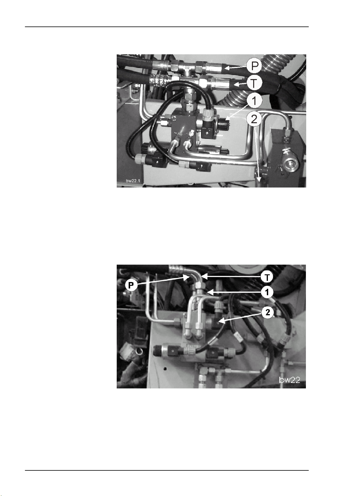
P Feed line to UNIWRAP.
T Return line from UNIWRAP.
28 UNI-h-Kap1 11/04
1 Tee
2 Circulation shut-off valve solenoid coil (Y77-1)
P Feed line to UNIWRAP.
T Return line from UNIWRAP.
Page 29

TIC UNIWRAP Hydraulic System
2.2 Connection to tractor hydraulic system
Description of function: 1/2
The attachment can be connected to any tractor hydraulic system
available on the market.
Connection to tractors with
constant-flow hydraulic
system
The quick release coupling 1 is connected to a control unit port of the
tractor with adjustable oil flow.
This control unit provides oil supply for the attachment and is adjusted to
a constant volume flow of Q
The system screw 634 is turned out up to the stop so that the input
pressure balance 763 is operative.
The quick release coupling 2 is in general connected to the pressureless
return line T of the tractor.
If a pressureless return line is not allowed in continuous operation (e.g.
because lubrication of the tractor gearbox is not guaranteed), a doubleacting control unit can be used for supplying oil to the attachment.
In this case, the quick release coupling 1 is connected to port A (feed) and
quick release coupling 2 to port B (return) of the corresponding tractor
control valve.
Adjust the volume flow to Q
tractor's Operating Manual (e.g. "Continuous operation of hydraulic
motors").
The LS connection (LS, working hydraulics signal) is not used here.
If the tractor is not provided with a flow-adjustable control unit, the volume
flow must not exceed 35 to 50 l/min.
Connection to tractors with
constant-pressure hydraulic
system
The quick release coupling 1 is connected to a control unit port of the
tractor with adjustable oil flow.
This control unit provides oil supply for the attachment and is adjusted to
an oil flow of Q
= 35 to 50 l/min.
max
The system screw 634 is turned in up to the stop so that the input
pressure balance 763 is blocked.
The tractor's hydraulic pump is shut down when the system pressure has
been reached.
The quick release coupling 2 is connected to port T (pressureless return
line) of the tractor.
The LS connection (LS, working hydraulics signal) is not used here.
= 35 to 50 l/min.
max
= 35 to 50 l/min; please refer also to the
max
11/04 UNI-h-Kap2 29
Page 30

Hydraulic System UNIWRAP TIC
Description of function: 2/2
Connection to tractors with
load-sensing system and a
Power Beyond port
Test points/characteristics When no function is active on the attachment, the attachment must not
Connection to tractors with
load-sensing system without
a Power Beyond port
The quick release coupling 1 is connected directly to the pump via the
Power Beyond port P.
The quick release coupling 2 is connected to port T (pressureless return
line) of the tractor.
Here the LS connection (LS, working hydraulics signal) is connected with
the LS signal port of the tractor (the kit is available from the spare parts
department).
The system screw 634 is turned in up to the stop so that the input
pressure balance 763 is blocked.
The tractor's hydraulic pump regulates as a function of the attachment's
load signal.
load the tractor hydraulically.
(The tractor engine speed must not be reduced).
The allowed temperature of the tractor's hydraulic system must not be
exceeded; see also the Operator's Manual of the tractor.
The quick release coupling 1 is connected to a control unit port of the
tractor with adjustable oil flow.
This control unit provides oil supply for the attachment and is adjusted to
a constant volume flow of Q
= 35 to 50 l/min.
max
The system screw 634 is turned out up to the stop so that the input
pressure balance 763 is operative.
The quick release coupling 2 is in general connected to the pressureless
return line T of the tractor.
If a pressureless return line is not allowed in continuous operation (e.g.
because lubrication of the tractor gearbox is not guaranteed), a doubleacting control unit can be used for supplying oil to the attachment.
In this case, the quick release coupling 1 is connected to port A (feed) and
quick release coupling 2 to port B (return) of the corresponding tractor
control valve.
Adjust the volume flow to Q
= 35 to 50 l/min; please refer also to the
max
tractor's Operating Manual (e.g. "Continuous operation of hydraulic
motors").
The LS connection (LS, working hydraulics signal) is not used here.
If the tractor is not provided with a flow-adjustable control unit, the volume
flow must not exceed 35 to 50 l/min.
30 UNI-h-Kap1 11/04
Page 31

TIC UNIWRAP Hydraulic System
3
Valve block
3.1 Valve block, up to machine no. 130 ................................................34
3.2 Valve block - from machine no. 131,
with tipping cradle service shut-off valve (631) ...............................38
11/04 UNI-h-Kap3 31
Page 32

Hydraulic System UNIWRAP TIC
32 UNI-h-Kap3 11/04
Page 33

3.1
Valve block
- up to machine no. 130
Page 34

Hydraulic System UNIWRAP TIC
3.1 Valve block, up to machine no. 130
34 UNI-h-Kap3 11/04
Page 35

TIC UNIWRAP Hydraulic System
Key to diagram:
F Screw plug
Access to flow controller.
Note: Screw plug F must not protrude.
P Pump (supply line)
T Return line (tank)
3a Intermediate plate
763 Input pressure balance
767 Wrapping arm motor flow controller
768 LS signal shuttle valves
Y77 Master valve solenoid valve
Y133 Wrapping arm motor forward solenoid valve
Y135 Lower tipping cradle solenoid valve
Y136 Raise tipping cradle solenoid valve
Y137 Lower wrapping table solenoid valve
Y138 Raise wrapping table solenoid valve
11/04 UNI-h-Kap3 35
Page 36

Hydraulic System UNIWRAP TIC
Description of function:
Intermediate plate (3a) A connection from P to T is open in the intermediate plate.
The LS connection is closed.
Input pressure balance
(763)
The input pressure balance keeps the connection from P to T open when
no control unit is actuated in valve block 3.
It is closed by LS pressure. The LS pressure is built up when the master
valve (Y77-2) or a control unit in valve block 3 is actuated.
Wrapping arm motor flow
controller (767)
The flow controller keeps the volume flow to the wrapping arm motor
(234) constant.
Maximum wrapping speed (approx. 20 l/min.) with SAM wrapping arm
motor.
Maximum wrapping speed (approx. 31 l/min.) with Danfoss wrapping arm
motor.
LS signal shuttle valves
(768)
When operating the control valves in parallel mode, the shuttle valves
allow sending the highest load pressure to the input pressure balance
(763) in each case.
Master valve solenoid valve
(Y77)
The master valve solenoid valve is actuated automatically when a
hydraulic function is to be carried out on the baler.
Now the pump flow is directed into the LS line so that the pressure that
builds up closes the pressure balance (763). Now the entire volume flow
of the baler is available for performing hydraulic functions.
Wrapping arm forward
solenoid valve (Y133)
Controls the wrapping arm hydraulic motor.
A flow control valve is provided in the volume flow input which limits the
volume flow to approx. 20l/min on the SAM wrapping arm motor or
approx. 31l/min on the Danfoss wrapping arm motor. When the control
unit is activated, this volume flow is pumped to the wrapping arm motor
(234) which drives the wrapping arm with 28 ... 30 rpm max.
The flow controller may be accessed via the screw plug (F) at the bottom
of the control unit.
If required, adjust the maximum rotational speed of the wrapping arm
between 28 ... 30 rpm by carefully turning in or our the screw.
Screw plug (F) must not protrude. The rotational speed of 28 ... 30 rpm
ensures that the wrapping process is shorter than the time required for
producing the bale.
Lower tipping cradle
The solenoid valve lowers the tipping cradle.
solenoid valve (Y135)
Raise tipping cradle
solenoid valve (Y136)
The solenoid valve raises the tipping cradle. The lock-up valve unit 734
avoids lowering of the raised tipping cradle.
Lower wrapping table
solenoid valve (Y137)
The solenoid valve lowers the wrapping table. The lock-up valve unit 734
in the cylinder line avoids lowering of the loaded wrapping table.
Raise wrapping table
The solenoid valve raises the wrapping table.
solenoid valve (Y138)
36 UNI-h-Kap3 11/04
Page 37

3.2
Valve block
- from machine no. 131
- with tipping cradle service shut-off valve (631)
Page 38

Hydraulic System UNIWRAP TIC
3.2 Valve block - from machine no. 131, with tipping cradle service shut-off valve (631)
38 UNI-h-Kap3 11/04
Page 39

TIC UNIWRAP Hydraulic System
Key to diagram:
F Screw plug
Access to flow controller.
Note: Screw plug F must not protrude.
P Pump (supply line)
T Return line (tank)
3a Intermediate plate
763 Input pressure balance
767 Wrapping arm motor flow controller
768 LS signal shuttle valves
Y77 Master valve solenoid valve
Y133 Wrapping arm motor forward solenoid valve
Y135 Lower tipping cradle solenoid valve
Y136 Raise tipping cradle solenoid valve
Y137 Lower wrapping table solenoid valve
Y138 Raise wrapping table solenoid valve
11/04 UNI-h-Kap3 39
Page 40

Hydraulic System UNIWRAP TIC
Description of function:
Intermediate plate (3a) A connection from P to T is open in the intermediate plate.
The LS connection is closed.
Input pressure balance
(763)
The input pressure balance keeps the connection from P to T open when
no control unit is actuated in valve block 3.
It is closed by LS pressure. The LS pressure is built up when the master
valve (Y77-2) or a control unit in valve block 3 is actuated.
Wrapping arm motor flow
controller (767)
The flow controller keeps the volume flow to the wrapping arm motor
(234) constant.
Maximum wrapping speed (approx. 20 l/min.) with SAM wrapping arm
motor.
Maximum wrapping speed (approx. 31 l/min.) with Danfoss wrapping arm
motor.
LS signal shuttle valves
(768)
When operating the control valves in parallel mode, the shuttle valves
allow sending the highest load pressure to the input pressure balance
(763) in each case.
Master valve solenoid valve
(Y77)
The master valve solenoid valve is actuated automatically when a
hydraulic function is to be carried out on the baler.
Now the pump flow is directed into the LS line so that the pressure that
builds up closes the pressure balance (763). Now the entire volume flow
of the baler is available for performing hydraulic functions.
Wrapping arm forward
solenoid valve (Y133)
Controls the wrapping arm hydraulic motor.
A flow control valve is provided in the volume flow input which limits the
volume flow to approx. 20 l/min on the SAM wrapping arm motor or
approx. 31l/min on the Danfoss wrapping arm motor. When the control
unit is activated, this volume flow is pumped to the wrapping arm motor
(234) which drives the wrapping arm with 28 ... 30 rpm max.
The flow controller may be accessed via the screw plug (F) at the bottom
of the control unit.
If required, adjust the maximum rotational speed of the wrapping arm
between 28 ... 30 rpm by carefully turning in or our the screw.
Screw plug (F) must not protrude. The rotational speed of 28 ... 30 rpm
ensures that the wrapping process is shorter than the time required for
producing the bale.
Lower tipping cradle
The solenoid valve lowers the tipping cradle.
solenoid valve (Y135)
Raise tipping cradle
solenoid valve (Y136)
The solenoid valve raises the tipping cradle. The lock-up valve unit 734
avoids lowering of the raised tipping cradle.
Lower wrapping table
solenoid valve (Y137)
The solenoid valve lowers the wrapping table. The lock-up valve unit 734
in the cylinder line avoids lowering of the loaded wrapping table.
Raise wrapping table
The solenoid valve raises the wrapping table.
solenoid valve (Y138)
40 UNI-h-Kap3 11/04
Page 41

TIC UNIWRAP Hydraulic System
4
Individual components
4.1 Input pressure balance (763) ..........................................................42
4.2 Circulation shut-off valve (Y77-2)....................................................46
4.3 Wrapping arm control unit (Y133) ...................................................50
4.4 Tipping cradle control unit (Y135 / Y136)........................................54
4.4.1 Up to serial no.: with lock-up valve unit...............................54
4.4.2 From serial no.: without lock-up valve unit ..........................58
4.5 Wrapping table control unit (Y137 / Y138) ......................................62
4.6. Clamping cutters control unit (Y139 / Y140) ...................................66
4.7 Flow controller (630)........................................................................70
4.8 Pressure relief valve (706) ..............................................................74
4.9 Wrapping arm motor (234) ..............................................................76
4.10 Wrapping table motor (235).............................................................78
4.11 Tipping cradle service shut-off valve (631) .....................................80
4.12 Film clamping cutters hydraulic cylinder (374) ................................82
4.13 Film clamping cutters flow divider (769)..........................................84
4.14 Wrapping arm motor valve block (4) ...............................................90
4.15 3-stage restrictor .............................................................................92
4.16 Valve combination (7)......................................................................94
4.17 Manifold (8) .....................................................................................96
11/04 UNI-h-Kap4 41
Page 42

Hydraulic System UNIWRAP TIC
4.1 Input pressure balance (763)
42 UNI-h-Kap4 11/04
Page 43

TIC UNIWRAP Hydraulic System
Key to diagram:
P Channel pump
Volume flow input from the baler. Channel P continues through
each downstream control unit and is connected with the spool
in each case.
P1 Port. Supply of film cutter control unit
LS The LS channel is connected to each of the downstream
control units. Here the load pressure is applied when a control
unit is actuated.
T Return line (tank).
The channel T continues through each of the downstream
control units and is connected with the spool in each case.
T1 Port.
Return line input from the film cutter control unit.
1 Control ram
The compression spring pushes it to the left-hand stop when no
volume flow is flowing.
3 Bore
It connects the LS channel (load pressure) with the spring
space of the control ram.
634 System screw (option)
763 Input pressure balance
11/04 UNI-h-Kap4 43
Page 44

Hydraulic System UNIWRAP TIC
44 UNI-h-Kap4 11/04
Page 45

TIC UNIWRAP Hydraulic System
Description of function:
No volume flow flowing
The pressure spring pushes the control piston (1) to the left-hand stop.
The connection from P to T is closed.
Volume flow flowing – but
no control unit is actuated
The compression spring pushes the control ram (1) to its left-hand stop.
The connection from P to T is closed.
Volume flow enters the pressure balance via channel P (from the tractor
via the baler) and flows to each of the downstream control units. Since no
control unit is actuated, each spool shuts off the volume flow.
This builds up pressure which acts on the left-hand face end of the
control piston (1) and moves it to the right against the pressure spring.
Now the connection from P to T is opened so that the volume flow flows
back to the baler.
At the same time, a partial volume flow flows via the orifice plate (inside
the control piston) into the spring space of the control piston. The spring
space is pressureless because it is connected with the channel (LS) via
bore (3). This channel is pressureless, too, because no control unit is
actuated.
A pressure difference (∆p) of 9 bar results at the control piston because:
pressure ahead of the control piston = 9 bar
pressure in the spring space = 0 bar
A control unit is actuated,
e.g. the tipping cradle is
raised.
When the corresponding control unit is actuated, volume flow flows via
channel P and the spool into the tipping cradle cylinders. The load
pressure now generated is directed into the control piston spring space
through the LS channel and via bore (3).
This pressure build-up moves the control piston (1) to the left, partly
closing the connection from P to T. This closing is necessary to make
volume flow available for raising the tipping cradle.
However, the control piston is pushed to the left only until the pressure
difference (∆p) of 9 bar is re-established. A part of the volume flow will
continue to flow back to the baler via channel T.
When the tipping cradle cylinders have moved up to their stop, the
pressure rises and is applied in the control piston spring space via the LS
channel and pushes the control piston to the left-hand stop. The pressure
inside channel P actuates the pressure relief valve on the tractor (the
baler and the UNIWRAP are supplied with volume flow from here).
11/04 UNI-h-Kap4 45
Page 46

Hydraulic System UNIWRAP TIC
4.2 Circulation shut-off valve (Y77-2)
46 UNI-h-Kap4 11/04
Page 47

TIC UNIWRAP Hydraulic System
Key to diagram:
P Channel pump
Volume flow input from the baler. Channel P continues through
each downstream control unit and is connected with the spool
in each case.
T Return line (tank).
The channel T continues through each of the downstream
control units and is connected with the spool in each case.
A Port.
The connection is closed.
B Port.
The connection is closed.
LS The LS channel is connected to each of the downstream
control units. Here the load pressure is applied when a control
unit is actuated.
1 Spool.
Actuated by solenoid valve (3).
2 Bore
in the spool. It is connected with the LS channel that ends at
the upstream input pressure balance.
Y77-2 Master valve solenoid valve
It actuates the spool (1).
768-1 LS signal shuttle valves
11/04 UNI-h-Kap4 47
Page 48

Hydraulic System UNIWRAP TIC
Description of function:
The circulation shut-off valve solenoid coil (Y77-2) is actuated whenever a
hydraulic function is to be carried out on the baler (e.g. open tailgate, raise
pick-up ...).
No volume flow flowing
Due to the two pressure springs located at the face end, spool (2) is
positioned so that (see figure):
- channel P is shut off at the spool
- ports A and B are connected with the tank
- bore (2) is connected with the tank.
Hydraulic requirement from
the baler
The UNIWRAP electronics module actuates circulation shut-off valve
solenoid coil (Y77-2). Solenoid coil (Y77-2) moves spool (1) to the lefthand stop, thus opening the connection from P to A. Since port A is
closed, pressure is built up which then is applied in the LS channel via
bore (2) and LS signal shuttle valve (768-1). This pressure signal is
directed to the upstream input pressure balance (763) via the LS
channel.The pressure balance (763) switches over and shuts off the
connection from P to T which had been open so far. The volume flow is
now available to the baler.
48 UNI-h-Kap4 11/04
Page 49

TIC UNIWRAP Hydraulic System
11/04 UNI-h-Kap4 49
Page 50

Hydraulic System UNIWRAP TIC
4.3 Wrapping arm control unit (Y133)
50 UNI-h-Kap4 11/04
Page 51

TIC UNIWRAP Hydraulic System
Key to diagram:
P Channel pump
Volume flow input from the baler. Channel P continues through
each downstream control unit and is connected with the spool
in each case.
T Return line (tank)
The channel T continues through each of the downstream
control units and is connected with the spool in each case.
LS The LS channel is connected to each of the downstream
control units.
When the wrapping arm rotates, the load pressure acts here.
This pressure signal ends in the input pressure balance.
A Port
The wrapping arm hydraulic motor is connected here.
B Port
The connection is closed.
1 Spool
Actuated by solenoid valve (6).
2 Bore
In the spool, senses the load pressure in port A. Is connected
with the LS channel which ends in the input pressure balance.
3 2-way flow controller
It limits the max. volume flow to the wrapping arm motor to
20 l/min, resulting in a wrapping arm speed of 28 ... 30 l/min.
3a Orifice plate
3b Connection
Is a spiral groove which directs the load pressure from
port A (wrapping arm hydraulic motor) into the spring
space.
4 Spring support
This allows changing the spring force.
767 Wrapping arm motor flow controller
768-2 LS signal shuttle valve
Y133 Solenoid valve
- Is a proportional solenoid valve and actuates spool (1).
- Is actuated by the UNIWRAP electronics module.
11/04 UNI-h-Kap4 51
Page 52

Hydraulic System UNIWRAP TIC
Description of function:
No volume flow flowing Due to the two pressure springs located at the face end, spool (2) is
positioned so (see figure) that ports P and A are shut off.
Oil supply is available, but
control unit is not yet
actuated
The volume flow enters the control unit via channel P and flows through
orifice plate (3a) to spool (1).
Since the spool stops the flow, pressure is built up which acts on the
right-hand face end of the 2-way flow controller (3) and via connection
(3b) also in the spring space.
This compensates the pressure at the 2-way flow controller (3) which is
pushed to the right-hand stop by the pressure spring.
Control unit is actuated The speed of the hydraulic motor which drives the wrapping arm depends
on the amount of volume flow.
The higher the volume flow, the higher the motor speed. When the input
volume flow is constant, the hydraulic motor speed will be constant as
well.
When the wrapping arm starts, its speed is to be continuously increased
from 0 to 28 ... 30 rpm. To realise this start-up behaviour, the volume flow
to the hydraulic motor must be continuously increased.
The UNIWRAP electronics module actuates the solenoid coil (Y133) and
continuously increases its force which moves the spool (1) against the
pressure spring to the left.
This opens the connection from P to A continuously, thus constantly
increasing the volume flow and consequently the hydraulic motor speed.
When the solenoid coil (Y133) has moved the spool (1) fully to the left
against the pressure spring, the spool gap has reached its maximum
opening position.
In this position, the 2-way flow controller (767) regulates the volume flow
to approx. 20 l/min on the SAM wrapping arm motor or approx. 31 l/min
on the Danfoss wrapping arm motor, independently from the load.
This keeps the hydraulic motor speed constant.
52 UNI-h-Kap4 11/04
Page 53

TIC UNIWRAP Hydraulic System
Control behaviour When volume flow flows through the 2-way flow controller (767), different
pressure levels are generated:
- The pump pressure is applied ahead of the orifice plate (3a)
- The load pressure is applied behind the orifice plate (3a) via
connection (3b).
The pressure behind the orifice plate (3a) is lower than the pressure
ahead of the orifice plate. This pressure difference is referred to as ∆p.
The flow controller keeps this ∆p constant even when the load pressure
(in the spring space) changes. When ∆p is constant, the volume flow is
also constant.
Load pressure The load pressure generated is directed through the hollow-drilled spool
via bore (2), actuates the LS signal shuttle valve (768-2) and is then
transmitted into the LS channel which ends at the upstream input
pressure balance (763).
11/04 UNI-h-Kap4 53
Page 54

Hydraulic System UNIWRAP TIC
4.4 Tipping cradle control unit (Y135 / Y136)
4.4.1 Up to serial no.: with lock-up valve unit
54 UNI-h-Kap4 11/04
Page 55

TIC UNIWRAP Hydraulic System
Key to diagram:
P Channel pump
Volume flow input.
T Return line (tank)
LS LS channel.
When the tipping cradle is actuated, the load pressure acts
here. This pressure signal ends in the input pressure balance.
A Port
To the rod spaces of the hydraulic cylinders. The tipping cradle
is raised when pressure is built up.
B Port
To the piston spaces of the hydraulic cylinders. The tipping
cradle is lowered when pressure is built up.
1 Spool
Actuated by solenoid valve (6).
4 Ram
Opens the non-return valve (734-1) or (734-2)
734-1 Lock-up valve unit non-return valve
This seals off port A and is opened by ram (4).
734-2 Lock-up valve unit non-return valve
This seals off port B and is opened by ram (4).
768-3 LS signal shuttle valve
Y136 Raise tipping cradle solenoid valve
The solenoid valve moves the spool (1) to the left.
Y135 Lower tipping cradle solenoid valve
The solenoid valve moves the spool (1) to the right.
11/04 UNI-h-Kap4 55
Page 56

Hydraulic System UNIWRAP TIC
Description of function:
No volume flow flowing,
the solenoid valves are not
actuated.
Due to the two pressure springs located at the face end, spool (1) is
positioned so (see figure) that port P is shut off.
Ports A and B are sealed by the non-return valves.
Raise tipping cradle Solenoid coil (Y136) is actuated by the UNIWRAP electronics module and
moves spool (1) to the left.
Volume flow flows from channel P via the spool gap in front of the lock-up
valve unit non-return valve (734-1). Pressure is built up which:
- opens the lock-up valve unit non-return valve (734-1) and
- moves the piston (4) to the right.
The volume flow flows from port A via the open lock-up valve unit nonreturn valve (734-1) into the rod spaces of the hydraulic cylinders - the
tipping cradle is raised.
At the same time, the piston (4) is moved to the right and opens the lockup valve unit non-return valve (734-2). Port B (piston spaces of hydraulic
cylinders) is connected with the tank (T1) via the open lock-up valve unit
non-return valve (734-2) and spool (1).
Lower tipping cradle Solenoid coil (Y135) is actuated by the UNIWRAP electronics module and
moves spool (1) to the right.
Volume flow flows from channel P via the spool gap in front of the lock-up
valve unit non-return valve (734-2). Pressure is built up which:
- opens the lock-up valve unit non-return valve (734-2) and
- moves the piston (4) to the left.
The volume flow from port B flows via the open lock-up valve unit nonreturn valve (734-2) into the piston spaces of the hydraulic cylinders - the
tipping cradle is lowered.
At the same time, the piston (4) is moved to the left and opens the lockup valve unit non-return valve (734-1). Port A (rod spaces of the hydraulic
cylinders) is connected with the tank (T) via the open lock-up valve unit
non-return valve (734-1) and spool (1).
56 UNI-h-Kap4 11/04
Page 57

TIC UNIWRAP Hydraulic System
Notes:
11/04 UNI-h-Kap4 57
Page 58

Hydraulic System UNIWRAP TIC
4.4 Tipping cradle control unit (Y135 / Y136)
4.4.2 From serial no.: without lock-up valve unit
58 UNI-h-Kap4 11/04
Page 59

TIC UNIWRAP Hydraulic System
Key to diagram:
P Channel pump
Volume flow input.
T, T1 Return line (tank)
LS LS channel
When the tipping cradle is actuated, the load pressure acts
here. This pressure signal ends in the input pressure balance.
A Port
To the rod spaces of the hydraulic cylinders. The tipping cradle
is raised when pressure is built up.
B Port
To the piston spaces of the hydraulic cylinders. The tipping
cradle is lowered when pressure is built up.
1 Spool
Actuated by solenoid valve (6).
768-3 LS signal shuttle valve
Y136 Raise tipping cradle solenoid valve
The solenoid valve moves the spool (1) to the left.
Y135 Lower tipping cradle solenoid valve
The solenoid valve moves the spool (1) to the right.
11/04 UNI-h-Kap4 59
Page 60

Hydraulic System UNIWRAP TIC
Description of function:
No volume flow flowing,
the solenoid valves are not
Due to the two pressure springs located at the face end, spool (1) is
positioned so (see figure) that port P is shut off.
actuated.
Raise tipping cradle Solenoid coil (Y136) is actuated by the UNIWRAP electronics module and
moves spool (1) to the left.
Volume flow flows from channel P via the spool gap to port A and
continues into the rod spaces of the hydraulic cylinders – the tipping
cradle is raised.
At the same time, volume flow from the piston spaces of the hydraulic
cylinders flows via port B into the tank (T1).
Lower tipping cradle Solenoid coil (Y135) is actuated by the UNIWRAP electronics module and
moves spool (1) to the right.
Volume flow flows from channel P via the spool gap to port B and
continues into the piston spaces of the hydraulic cylinders – the tipping
cradle is lowered.
At the same time, the volume flow from the rod spaces of the hydraulic
cylinders flows via port A into the tank (T).
60 UNI-h-Kap4 11/04
Page 61

TIC UNIWRAP Hydraulic System
Notes:
11/04 UNI-h-Kap4 61
Page 62

Hydraulic System UNIWRAP TIC
4.5 Wrapping table control unit (Y137 / Y138)
62 UNI-h-Kap4 11/04
Page 63

TIC UNIWRAP Hydraulic System
Key to diagram:
P Channel pump
Volume flow input.
T, T1 Return line (tank)
LS LS channel
When the wrapping table is raised, the load pressure acts here.
This pressure signal ends in the input pressure balance.
A Port
Is closed.
B Port
To the rod spaces of the hydraulic cylinders. The wrapping
table is raised when pressure is built up.
1 Spool
Actuated by solenoid valve (6).
734-1 Lock-up valve unit non-return valve
This seals off port A and is opened by ram (4).
734-2 Lock-up valve unit non-return valve
This seals off port B and is opened by ram (4).
4 Ram
Opens the non-return valve (734-1) or (734-2)
768-4 LS signal shuttle valve
Y137 Lower wrapping table solenoid valve
The solenoid valve moves the spool (1) to the left.
Y138 Raise wrapping table solenoid valve
The solenoid valve moves the spool (1) to the right.
11/04 UNI-h-Kap4 63
Page 64

Hydraulic System UNIWRAP TIC
Description of function:
No volume flow flowing,
the solenoid valves are not
actuated.
Due to the two pressure springs located at the face end, spool (1) is
positioned so (see figure) that port P is shut off.
Port B is sealed by non-return valve (2).
Raise wrapping table Solenoid coil (Y138) is actuated by the UNIWRAP electronics module and
moves spool (1) to the right.
Volume flow flows from channel P via the spool gap in front of the lock-up
valve unit non-return valve (734-2). Pressure is built up which:
- opens the lock-up valve unit non-return valve (734-2) and
- moves the piston (4) to the left.
The volume flow flows via port B and via the open lock-up valve unit nonreturn valve (734-2) into the rod spaces of the hydraulic cylinders – the
wrapping table is raised.
Lower wrapping table Solenoid coil (Y137) is actuated by the UNIWRAP electronics module and
moves spool (1) to the left.
Volume flow flows from channel P via the spool gap in front of the lock-up
valve unit non-return valve (734-1). Pressure is built up which:
- opens the lock-up valve unit non-return valve (734-1)
(without importance here since port A is closed) and
- moves the piston (4) to the right.
The movement of the piston (4) to the right opens the lock-up valve unit
non-return valve (734-2). Port B (rod spaces of hydraulic cylinders) is
connected with the tank (T1) via the open lock-up valve unit non-return
valve (734-2) and the spool (1).
64 UNI-h-Kap4 11/04
Page 65

TIC UNIWRAP Hydraulic System
Notes:
11/04 UNI-h-Kap4 65
Page 66

Hydraulic System UNIWRAP TIC
4.6. Clamping cutters control unit (Y139 / Y140)
66 UNI-h-Kap4 11/04
Page 67

TIC UNIWRAP Hydraulic System
Key to diagram:
P Channel pump
Volume flow input.
T Return line (tank)
A Port
to the rod space of the right hydraulic cylinder.
B Port
to the ram space of the left hydraulic cylinder.
1 Ball
It is opened by the magnetic tappet (2).
When not energized, it closes port P.
2 Magnetic tappet
It is pushed down by the solenoid valve (Y139, Y140) and
opens ball (1).
7 Ram
Opens the non-return valve (734-1) or (734-2)
734-1 Lock-up valve unit non-return valve
This seals off port A and is opened by ram (4).
734-2 Lock-up valve unit non-return valve
This seals off port B and is opened by ram (4).
Y139 Open film cutters solenoid valve
is controlled by the UNIWRAP electronic module, actuates the
magnetic tappet (2) and thus opens the ball (1) = connection
from P to A.
Y140 Close film cutters solenoid valve
is controlled by the UNIWRAP electronic module, actuates the
magnetic tappet (2) and thus opens the ball (1) = connection
from P to B.
11/04 UNI-h-Kap4 67
Page 68

Hydraulic System UNIWRAP TIC
Description of function:
When de-energised, the balls (1) keep the pressure port P closed.
The load ports A and B are connected with tank T.
When a solenoid valve (Y139, Y140) is energized, the magnetic tappet
opens the ball (1) against the spring and the applied hydraulic pressure.
The connection from P to A or to B is released. At the same time, the ram
cone closes the feed line to the tank.
In this condition, a consumer connected to port “A” or “B” can perform
work.
After de-energizing solenoid valve (Y139, Y140), port A or B is relieved
again towards the tank.
68 UNI-h-Kap4 11/04
Page 69

TIC UNIWRAP Hydraulic System
Notes:
11/04 UNI-h-Kap4 69
Page 70

Hydraulic System UNIWRAP TIC
4.7 Flow controller (630)
Up to serial no.: 72601047
70 UNI-h-Kap4 11/04
Page 71

TIC UNIWRAP Hydraulic System
Key to diagram:
P Input for total volume flow = Return oil from wrapping arm
hydraulic motor (approx. 17 l/min)
A Port
Constant flow output to wrapping table hydraulic motor.
B Port
Residual flow output to tank.
E Adjusting screw
Adjusts the pre-stress of the pressure spring
1 Orifice plate
In the control piston (3), produces the pressure difference ∆p
which determines the constant flow at port A.
2 Control edge
Controls the passage to port B
3 Control piston
- is pushed to the left-hand stop by the pressure spring when
no volume flow is flowing
- is moved by the pressure difference Dp at the orifice plate (1)
when volume flow flows.
4 Bore
The constant flow to port A flows via this bore.
6 Connecting bore
Directs the pressure behind the orifice plate into the spring
space
630 Flow controller
Divides the total volume flow (port P) into:
- a constant flow (port A) which drives the wrapping table
hydraulic motor and
- a residual flow (port B) which is directed into the tank.
11/04 UNI-h-Kap4 71
Page 72

Hydraulic System UNIWRAP TIC
Description of function:
The total volume flow enters the flow controller via port P and flows
through the orifice plate (1).
Here the pressure difference ∆p appears. The pressure downstream of
the orifice plate (1) is lower than the pressure upstream of it.
The flow controller keeps this ∆p constant, even when the pressure in
port A changes. With a constant ∆p at the orifice plate (1), the volume
flow leaving via port A and driving the wrapping table hydraulic motor is
constant.
The constant flow at output A can be adjusted to up to 6 l/min. with
adjusting screw (E). This allows continuous adjustment of the speed of
wrapping table rollers between 19 to 25 rpm.
- Low speed = large film overlap;
- High speed = small film overlap.
72 UNI-h-Kap4 11/04
Page 73

TIC UNIWRAP Hydraulic System
11/04 UNI-h-Kap4 73
Page 74

Hydraulic System UNIWRAP TIC
4.8 Pressure relief valve (706)
74 UNI-h-Kap4 11/04
Page 75

TIC UNIWRAP Hydraulic System
Key to diagram:
Description of function:
The pressure relief valve limits the pressure when lowering the tipping
630 Flow controller
706 Pressure relief valve
cradle to 70 bar.
It is installed below the valve block.
11/04 UNI-h-Kap4 75
Page 76

Hydraulic System UNIWRAP TIC
4.9 Wrapping arm motor (234)
76 UNI-h-Kap4 11/04
Page 77

TIC UNIWRAP Hydraulic System
Key to diagram:
Description of function:
When the wrapping arm rotates, the brake is opened by compressed oil.
W Wrapping arm drive shaft
234 Wrapping arm hydraulic motor
B Brake
P Feed line
T Return line
Y134 Wrapping arm backward solenoid coil
V Valve block
L Leakage oil line
When the wrapping arm is at standstill, the brake is mechanically closed,
preventing wrapping arm rotation by hand.
11/04 UNI-h-Kap4 77
Page 78

Hydraulic System UNIWRAP TIC
4.10 Wrapping table motor (235)
78 UNI-h-Kap4 11/04
Page 79

TIC UNIWRAP Hydraulic System
Key to diagram:
235 Wrapping table motor
11/04 UNI-h-Kap4 79
Page 80

Hydraulic System UNIWRAP TIC
4.11 Tipping cradle service shut-off valve (631)
80 UNI-h-Kap4 11/04
Page 81

TIC UNIWRAP Hydraulic System
Key to diagram:
Description of function:
The Tipping cradle service shut-off valve 631 is mounted directly on the
631 Tipping cradle service shut-off valve
control unit port.
For service work, the raised tipping cradle can be secured with the shutoff valve.
11/04 UNI-h-Kap4 81
Page 82

Hydraulic System UNIWRAP TIC
4.12 Film clamping cutters hydraulic cylinder (374)
82 UNI-h-Kap4 11/04
Page 83

TIC UNIWRAP Hydraulic System
Key to diagram:
Description of function:
The hydraulic cylinders are connected in series.
Non-return valves (628) The non-return valves 628 at the bottom of the rams are not opened
Bleeding the hydraulic
cylinders
When the cylinders are extended, the rings R open the non-return valves
374 Film clamping cutters hydraulic cylinder
628 Non-return valve
A Ram space port
B Rod space port
K Ram
R Ring
The film cutter cylinders extend when hydraulic pressure is applied at
port A.
The film cutter cylinders retract when hydraulic pressure is applied at
port B.
mechanically when the hydraulic cylinders are retracted.
628 at the top of the rams.
In this position (film clamping cutters are open), the hydraulic oil can flow
from A to B.
This position can be used for bleeding the cylinders.
11/04 UNI-h-Kap4 83
Page 84

Hydraulic System UNIWRAP TIC
4.13 Film clamping cutters flow divider (769)
84 UNI-h-Kap4 11/04
Page 85

TIC UNIWRAP Hydraulic System
Description of function:
Task
The flow divider divides the supplied volume flow (port P1) into 2 equal
Design
volume flows (ports P2 and P3). The hydraulic cylinders of the film cutters
are connected here.
These volume flows remain constant even when the loads from
consumers at ports (P2 and P3) change.
At equal volume flows, the speeds of the hydraulic cylinders are also
constant.
When the flow direction is reversed (from P2 and P3 to P1), the two
volume flows are combined into one total volume flow.
Item Designation Remark
1 Control ram
• Controls the opening cross-section of bore (2)
• Is mechanically connected with the control ram (4)
2 Bore The opening cross-section of the bore determines the partial volume flow at
port (P2)
3 Bore The opening cross-section of the bore determines the partial volume flow at
port (P3)
4 Control ram
• Controls the opening cross-section of bore (3)
• Is mechanically connected with the control ram (1)
F2 Compression
Loads control ram (1)
spring
F3 Compression
Loads control ram (4)
spring
F4 Compression
Loads both control rams (1, 4) so that they are mechanically connected
spring
P1 Port Total volume flow
P2 Port Partial volume flow
P3 Port Partial volume flow
11/04 UNI-h-Kap4 85
Page 86

Hydraulic System UNIWRAP TIC
Function
Open film cutters
while load on hydraulic
cylinders is identical
When the load on the hydraulic cylinders is identical, the control rams (1,
4) are subject to equal loads.
The compression springs position the two control rams so that the
opening cross-sections of the bores (2, 3) are identical.
The total volume flow enters the flow divider via port (P1).
Due to the identical opening cross-sections of bores (2, 3), the total
volume flow is divided into two equal volume flows which extend the
hydraulic cylinders via ports (P2, P3).
The film cutters open with the same speed.
86 UNI-h-Kap4 11/04
Page 87

TIC UNIWRAP Hydraulic System
Open film cutters
while load on hydraulic
cylinders is not identical
When the load on the hydraulic cylinders is not identical, the control rams
(1, 4) are subject to different loads. In the case shown here, the higher
load pressure exists at port (P2).
Without any control function, the hydraulic cylinder subject to the smaller
load (port P3) would extend first since the volume flow always flows
where resistance is the lowest.
Due to the control function, the load pressure in port (P2) moves the
control ram (1) to the right. This enlarges the opening cross-section of
bore (2).
The control ram (4) follows this movement so that the opening crosssection of bore (2) is reduced.
Due to the unequal opening cross-sections of bores (2, 3), the same
pressure drop is generated at each opening cross-section.
The total volume flow (port P1) is divided into two equal volume flows
(ports P2, P3). The hydraulic cylinders extend with the same speed
despite a different load.
11/04 UNI-h-Kap4 87
Page 88

Hydraulic System UNIWRAP TIC
Close film cutters
while load on hydraulic
cylinders is identical
When the load on the hydraulic cylinders is identical, the control rams (1,
4) are subject to equal loads.
The compression springs position the two control rams so that the
opening cross-sections of the bores (2, 3) are identical.
The equal partial volume flows (ports P2, P3) are combined into one total
volume flow (port P1).
The film cutters close with the same speed.
88 UNI-h-Kap4 11/04
Page 89

TIC UNIWRAP Hydraulic System
Close film cutters
while load on hydraulic
cylinders is not identical
When the load on the hydraulic cylinders is not identical, the control rams
(1, 4) are subject to different loads. In the case shown here, the higher
load pressure exists at port (P2).
Without any control function, the hydraulic cylinder subject to the higher
load (port P2) would retract first.
Due to the control function, the load pressure in port (P2) moves the
control ram (1) to the right. This reduces the opening cross-section of
bore (2).
The load pressure moves the control ram (4) in the spring space to the
right, thus enlarging the opening cross-section of bore (2).
Due to the unequal opening cross-sections of bores (2, 3), the same
pressure drop is generated at each opening cross-section.
The two unequal partial volume flows are combined into one total volume
flow (port P1). The hydraulic cylinders retract with the same speed despite
a different load.
11/04 UNI-h-Kap4 89
Page 90

Hydraulic System UNIWRAP TIC
4.14 Wrapping arm motor valve block (4)
F = Direction of travel of machine
Valve 764
Valve 765
F = Direction of travel
Valve 766
90 UNI-h-Kap4 11/04
Page 91

TIC UNIWRAP Hydraulic System
10
Key to diagram:
764 Wrapping arm motor drive pressure relief valve 115
765 Wrapping arm motor brake pressure relief valve 115
+
bar
+10
bar
766 Brake valve
F Direction of travel
Description of function:
Pressure relief valve (764) The wrapping arm motor drive pressure relief valve (764) limits the oil
pressure to the wrapping arm motor (234) and the wrapping table motor
(drive) connected in series to 115
+10
bar.
Pressure relief valve (765) The wrapping arm motor brake pressure relief valve limits the pressure of
the wrapping arm motor to 115
+10
bar while braking.
Brake valve (766) The brake valve (766) decelerates the wrapping arm motor hydraulically
on both sides when the wrapping arm forward solenoid valve (Y133) is
not actuated.
11/04 UNI-h-Kap4 91
Page 92

Hydraulic System UNIWRAP TIC
4.15 3-stage restrictor
92 UNI-h-Kap4 11/04
Page 93

TIC UNIWRAP Hydraulic System
Key to diagram:
Description of function:
To enable raising and lowering the wrapping table at different speeds, the
Valve position I In valve position I (operation without bale rotating mechanism), the
Valve position II In valve position II, raising and lowering of the wrapping table is via a
Valve position III In valve position III (operation with bale rotating mechanism), the
645 3-stage restrictor
I Valve position, restrictor Ø 1.5 mm
II Valve position, restrictor Ø 0.8 mm
III Valve position, restrictor Ø 1.5 mm
respective speed may be preselected using the 3-stage restrictor.
wrapping table is lowered and raised via a 1.5 mm orifice plate.
0.8 mm orifice plate.
This function is necessary in order to keep the bale rotating mechanism
from hitting the wrapping arm gearbox at high speed while swinging to
transport position.
wrapping table is raised via a 1.5 mm orifice plate.
Lowering the table is without any orifice plate (via the non-return valve) in
order to obtain a safe transfer of the bale onto the bale rotating
mechanism.
11/04 UNI-h-Kap4 93
Page 94

Hydraulic System UNIWRAP TIC
4.16 Valve combination (7)
94 UNI-h-Kap4 11/04
Page 95

TIC UNIWRAP Hydraulic System
Key to diagram:
Description of function:
The valve combination (7) combines the components (630, 706 and 769).
Wrapping table flow control
valve (630)
Pressure relief valve (706) The pressure relief valve limits the pressure to 70 bar when lowering the
Film clamping cutters flow
divider (769)
The wrapping table flow control valve supplies the hydraulic motor (235).
The flow divider divides the oil flows for opening and closing the film
630 Wrapping table flow control valve
706 Pressure relief valve
769 Film clamping cutters flow divider
This volume flow can be adjusted to up to 8 l/min. and changes the
wrapping table motor / wrapping arm motor speed ratio and consequently
the film layer overlaps.
- low speed = large film overlap;
- high speed = small film overlap
tipping cradle hydraulic cylinders (375).
clamping cutters.
11/04 UNI-h-Kap4 95
Page 96

Hydraulic System UNIWRAP TIC
4.17 Manifold (8)
96 UNI-h-Kap4 11/04
Page 97

TIC UNIWRAP Hydraulic System
Key to diagram:
Description of function:
The introduction of the manifold (8) simplifies the laying of lines on the
8 Manifold
UNIWRAP.
11/04 UNI-h-Kap4 97
Page 98

Hydraulic System UNIWRAP TIC
98 UNI-h-Kap4 11/04
Page 99

Following the policy of CLAAS KGaA mbH to improve
their products as technical developments continue,
CLAAS reserve the right to make alterations which
must not necessarily correspond to text and
illustrations contained in this publication, and without
Incurring obligation to alter any machines previously
delivered.
Technical data, dimensions and weights are given as
an indication only. Responsibility for errors or
omissions not accepted.
Reproduction or translation of this publication, in whole
or part, is not permitted without the written consent of
the CLAAS KGaA mbH.
All rights under the provision of the Copyright Act are
reserved.
CLAAS KGaA mbH
33426 Harsewinkel
Germany
Our contribution to the environment:
CLAAS has printed this manual
on 100 % chlorine free paper.
Page 100

CLAAS KGaA mbH
Postfach 1163
33426 Harsewinkel
Tel. +49 (0)5247 12-0
www.claas.com
0293 522.0
SYS-HY UNIWRAP
EN - 05.05 - NF
Printed in Germany
 Loading...