

Cissell KMAN589, UTILITY-MU-42-K, UTILITY-MU-45-K Service Manual
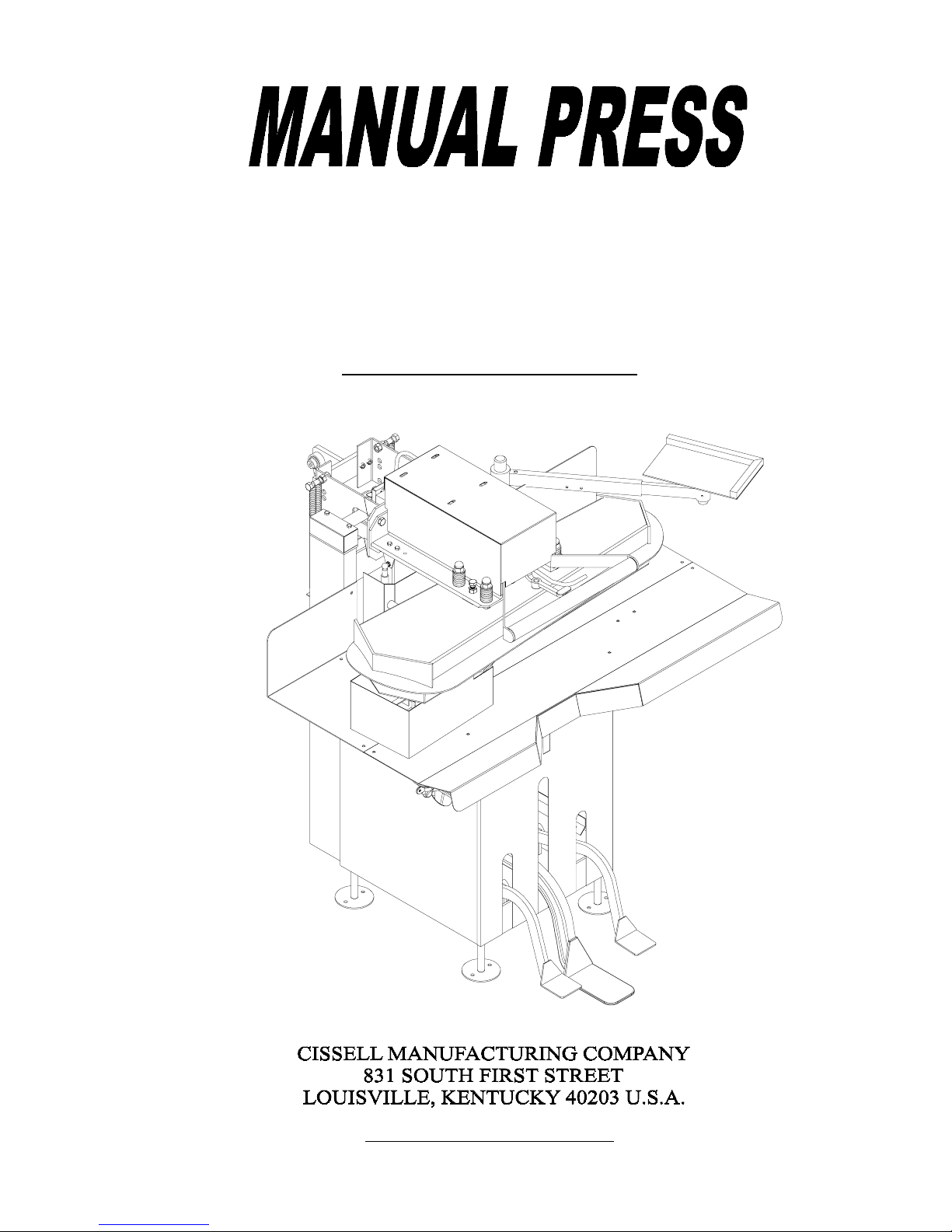
Service Manual
UTILITY- MU-42-K, MU-45-K
MAN589 ECN5736 31599

WARRANTY
Cissell Manufacturing Company (Cissell) warrants all new equipment (and the original parts thereof) to be free
from defects in material or workmanship for a period of one (1) year from the date of sale thereof to an original purchaser
for use, except as hereinafter provided. With respect to non-durable parts normally requiring replacement in less than one
(1) year due to normal wear and tear, including but not limited to, cloth goods, valve discs, hoses and iron cords, and with
respect to all new repair or replacement parts for Cissell equipment for which the one (1) year warranty period has
expired or for all new repair or replacement parts for equipment other than Cissell equipment, the warranty period is
limited to ninety (90) days from date of sale. The warranty period on each new replacement part furnished by Cissell in
fulfillment of the warranty on new equipment or parts shall be for the unexpired portion of the original warranty period on
the part replaced.
With respect to electric motors, coin meters and other accessories furnished with the new equipment, but not manufactured by Cissell, the warranty is limited to that provided by the respective manufacturer.
Cissell’s total liability arising out of the manufacture and sale of new equipment and parts, whether under the warranty or
caused by Cissell’s negligence or otherwise, shall be limited to Cissell repairing or replacing, at its option, any defective
equipment or part returned f.o.b. Cissell’s factory, transportation prepaid, within the applicable warranty period and found
by Cissell to have been defective, and in no event shall Cissell be liable for damages of any kind, whether for any injury
to persons or property or for any special or consequential damages. The liability of Cissell does not include furnishing
(or paying for) any labor such as that required to service, remove or install; to diagnose troubles; to adjust, remove or
replace defective equipment or a part; nor does it include any responsibility for transportation expense which is involved
therein.
The warranty of Cissell is contingent upon installation and use of its equipment under normal operating conditions. The
warranty is void on equipment or parts that have been subjected to misuse, accident or negligent damage; operated under
loads, pressures, speeds, electrical connections, plumbing, or conditions other than those specified by Cissell; operated or
repaired with other than genuine Cissell replacement parts; damaged by fire, flood, vandalism, or such other causes
beyond the control of Cissell; altered or repaired in anyway that affects the reliability or detracts from its performance; or
which have had the identification plate or serial number altered, effaced or removed.
No defective equipment or part may be returned to Cissell for repair or replacement without prior written authorization
from Cissell. Charges for unauthorized repairs will not be accepted or paid by Cissell.
CISSELL MAKES NO OTHER EXPRESSED OR IMPLIED WARRANTY, STATUTORY OR OTHERWISE, CONCERNING THE EQUIPMENT OR P ARTS INCLUDING, WITHOUT LIMITATION, A WARRANTY OF FITNESS
FOR A P A RTICULAR PURPOSE, OR A WARRANTY OF MERCHANTABILITY. THE WARRANTIES GIVEN
ABOVE ARE EXPRESSLY IN LIEU OF ALL OTHER WARRANTIES, EXPRESSED OR IMPLIED. CISSELL
NEITHER ASSUMES NOR AUTHORIZES ANY PERSON TO ASSUME FOR IT ANY OTHER WARRANTY OR
LIABILITY IN CONNECTION WITH THE MANUF ACTURE, USE OR SALE OF ITS EQUIPMENT OR PARTS.
For warranty service, contact the Distributor from whom the Cissell equipment or part was purchased. If the Distributor
cannot be reached, contact Cissell.
Page 2

T ABLE OF CONTENTS
MU42 and MU45 (UTILITY)
P AGE
Warranty………………………………………………………………………………………….. 2
Testing…………………………………………………………………………………………..... 5
Foreward ………………………………………………………………………………………… 5
Installing the Press ……………………………………………………………………………… 6
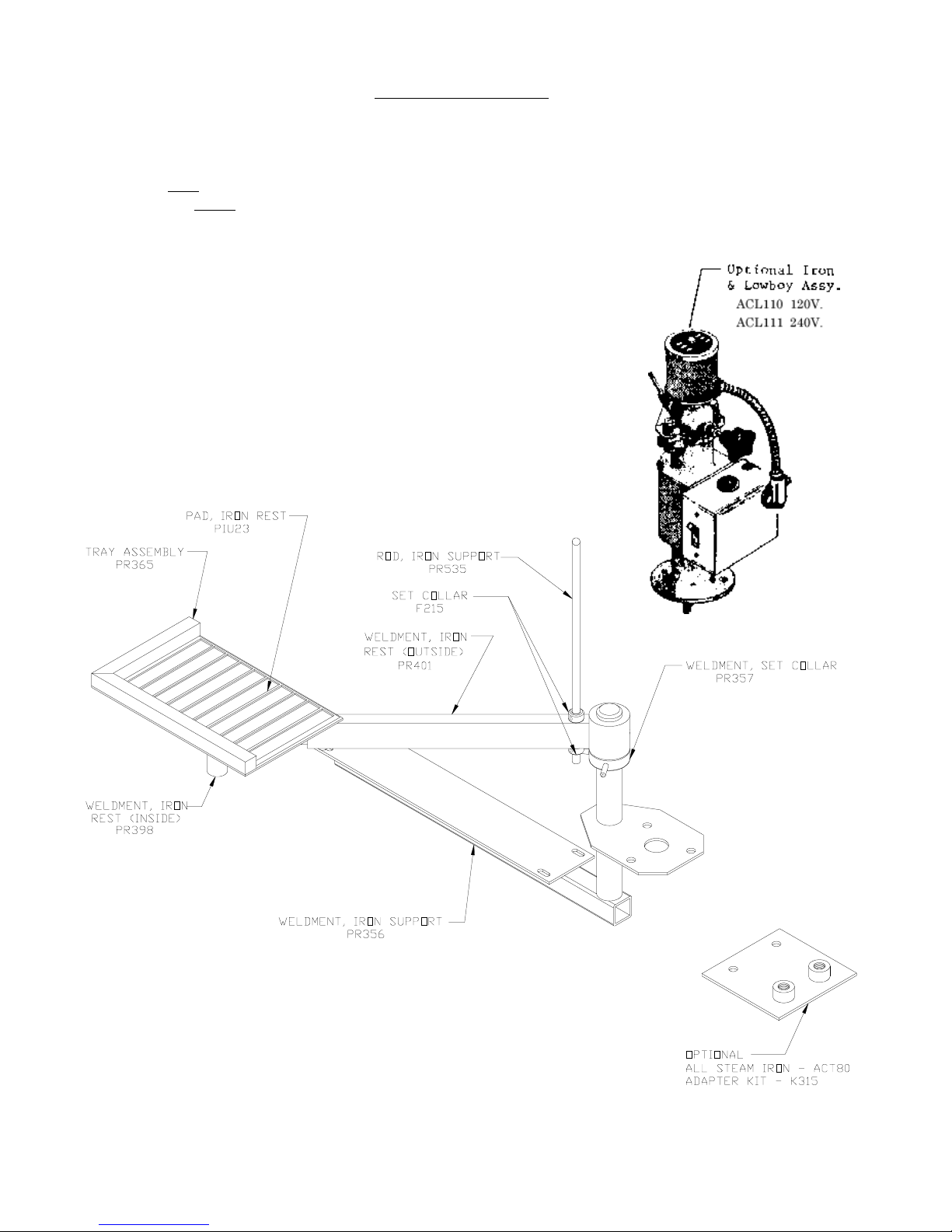
Fig. 1. Iron Rest Plate Group………………………………………………………… 6
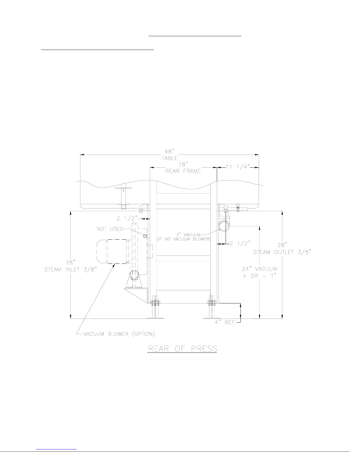
Fig. 2. Steam & Vacuum Connections……………………………………………….. 7
Fig. 3. Layout Foot Print....................………………………………………………... 9
Description of the Press…………………………………………………………………………. 9
Operation of the Press…………………………………………………………………………… 9
Overview of the Press ..................………………………………………………………. 1 0
Maintenance…………………………………………………………………………………......... 12
Adjustments …………………………………………………………………………………….... 1 2
Head Lever ……………………………………………………………………………... 12
Head Valve …………………………………………………………………………….... 12
Part Numbers:
Iron Rest Plate……………………………………………………………………........... 6
Lower Assembly....................................................................................................................... 11
Head Release Assembly (Lower Pivot)………………………………………………..... 1 4
Head Release Unit (Upper Pivot)……………………………………………………..... 1 5
Handle Assembly ……………………………………………………………………...... 1 6
Pivot Arm Assembly (upper)....………………………………………………………..... 1 7
Pivot Arm Assembly (Lower) ……………………………………………………........... 1 8
Table Assembly..... ………………………………………………………………............. 19
Steam & Vacuum Lever Assembly........………………………………………….............. 20
Cover & Foot Assembly........……………………………………………………............. 2 1
Pivot Arm Assembly ……………………………………………………………............. 22
Steam Connections ………………………………………………………………........... 2 3
Head Valve Unit …………………………………………………………......................... 24
Buck Valve Unit …………………………………………………………………............. 2 4
Page 3

TABLE OF CONTENTS
MU42, MU45, – UTILITY
PAGE
Buck Steam Linkage …………………………………………………………………… 20
General Trouble Shooting………………………………………………………………………… 1 2
Head will not lock ……………………………………………………………………… 1 2
Press Head bangs down when released .………………………………………………… 12
No vacuum ……………………………………………………………………………… 1 2
Vacuum will not shut off………………………………………………………………… 1 3
Buck Steam Valve releases too much or too little steam……………………………… 1 3
Wet spots on buck pad and covering …………………………………………………… 13
Defective check valve ………………………………………………………………… 1 3
Buck Valve leaking externally ………………………………………………………… 1 3
Head Valve leaking externally ………………………………………………………… 1 3
No head steam ………………………………………………………………………… 13
Page 4

TESTING
This press has been tested in the Cissell factory to determine that it is safe and in working order. Final adjustments must
be made to obtain the best results for your garments using your steam and vacuum in your environment.
The Cissell presses are manufactured and tested to the highest standards. The steam pressure vessels have been tested
with liquid to a pressure of 250 psi (17 bars). They have been tested for leaks with live steam at a pressure of 88 psi (6
bars).
On request, we can supply pressure certification and information regarding sizes and wall thickness of the vessel(s).
FOREWORD
Manual Foot Operated Presses
These modern presses are precision engineered to provide faster, easier operation than any other foot operated press. The
head is closed by hand and by foot operation of the central pedal. The head is opened by pressing down on the lever on
the right of the head steam valve. The head steam is hand lever operated while the buck steam and vacuum are foot pedal
operated. The improved leverage system and roller bearing pivot assures smoother, faster head operation and a quality
finish.
Page 5
INSTALLING THE PRESS
1. Uncrate the press and remove the skid. Move the press into position.
2. Hold the head down and cut the twine that holds the head closed. Allow the head to
rise slowly to the open position.
3. The Lowboy bracket (PR356) has been installed on the table at the factory. Then assemble the iron rest
assembly (PR365, PR398 & PR401) to the shaft of PR356. (See Figure 1)
FIGURE 1 (IRON REST)
Page 6
INSTALLING THE PRESS (Continued)
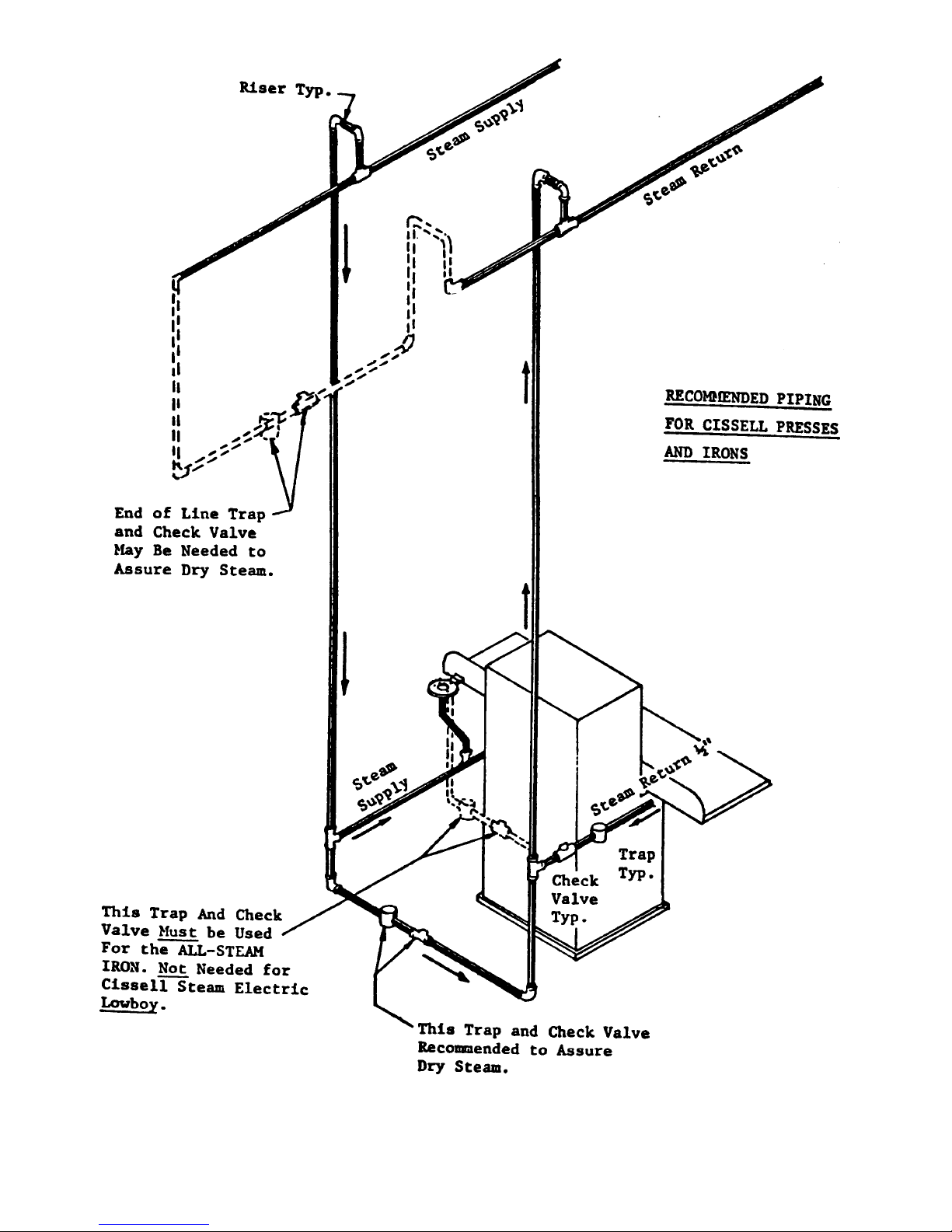
Steam and Vacuum Connections – (See Figure 2)
5. Connect a 3/8 inch steam supply line to the press at a recommended pressure of 88 psi
(6 bars). Use a reducing valve if needed to obtain the correct pressure. The press
uses one boiler horsepower (34.5 lb/h) of steam.
6. Connect a 3/8 inch steam return line to the press. Install a 1/2 inch steam trap suitable for
88 psi (6 bars) in the line.
7. Connect the vacuum using a 2 inch pipe to the vacuum supply. The vacuum supply should
be rated two presses or more. (Example: Cissell Dryset model 2D or larger).
FIGURE 2
STEAM & VACUUM CONNECTIONS
Page 7
Page 8
 Loading...