


 Loading...
MR74 Installation Guide
The Cisco Meraki MR74 is a dual-band enterprise class 802.11ac cloud-managed access point. Designed for general purpose network design, the MR74 meets the needs of the most demanding environments, and also includes the first ever cloud-managed third radio dedicated to optimizing the RF environment and securing the airwaves.
The Meraki MR74 has an operating temperature of -40o to 55o C.
Package Contents
The MR74 package contains the following:
•MR74 Cloud-Managed Access Point
•Mount cradle
•Wall screws
•Wall screw anchors
•Grounding screws
•Mounting straps
Understanding the MR74
LED indicator
Your MR74 is equipped with a multi-color LED light on the bottom edge of the unit to convey information about system functionality and performance:
•Orange - AP is booting (permanent Orange suggests hardware issue)
•Rainbow - AP is initializing/scanning
•Blinking Blue - AP is upgrading
•Green - AP in Gateway mode with no clients
•Blue - AP in Gateway mode with clients
•Blinking Orange - AP can't find uplink
The MR74 may be operated in “Run Dark” mode for additional security and to reduce the visibility of the access point. In this mode, the LED will not be illuminated. This mode may be enabled through the Meraki dashboard.
1
Ethernet Port
The MR74 features 1 Ethernet port:
The port labeled “PoE” accepts 802.3af power and should be used as the primary uplink to your LAN/WAN.
N-Type antenna attachment ports (4x)
2x N-Type antenna ports are located at the top of the MR74 and 2x are located at the bottom of the MR74. The pairs of antenna ports each correspond to the 2 client-serving radios. The spectrum that each pair serves is printed on the shell of the MR74. In order to ensure highest performance, ensure antennas connected to the 4 ports have overlapping coverage areas.
Mount plate attachment slots (4x)
The mounting slots located on the rear shell of the MR74 marry to the 4 mounting posts on the mounting plate, securely fastening the MR74 to the mounting plate.
Factory reset button
The factory reset button is located in a small pin-sized hole just above the PoE Ethernet port of the MR74. If the button is pressed and held for at least five seconds and then released, the MR74 will reboot and be restored to its original factory settings by deleting all configuration information stored on the unit.
The Vent
The vent allows pressure equalization between the interior and the environment. This prevents internal condensation and maintains a waterproof seal.
Understanding the MR74 mount plate
The mount plate is unique to the MR74. Previous outdoor AP mount plates are not compatible with the MR74.
The mount cradle has the following features:
2

Mounting posts (4x)
The mounting slots located in the middle of the mounting plate marry the MR74 to the mounting plate.
Mounting holes (4x)
The mounting holes located on the 4 outermost corners of the mounting plate allow secure installation of the mounting plate to a surface such as a wall.
Vertical orientation mounting strap slots (2x)
The vertical orientation mounting strap slots located in the middle of the mounting plate secure the mounting plate to a vertical pole using the included mounting straps.
Horizontal orientation mounting strap slots (2x)
The horizontal orientation mounting strap slots located in the middle of the mounting plate secure the mounting plate to a horizontal pole using the included mounting straps.
3

Release tab
The release tab located at the bottom of the mounting plate. It locks the movement of the AP once attached.
Mount plate attachment screw
The mount plate attachment screw is located at the bottom of the mounting plate. It securely attaches the AP to the mounting plate.
Mount plate grounding post
The mount plate grounding post located on the left side of the mounting plate. Using the included grounding strap, the ground post allows you to ground the unit.
Pre-Install Preparation
You should complete the following steps before going on-site to perform an installation.
Configure Your Network in Dashboard
The following is a brief overview only of the steps required to add an MR74 to your network. For detailed instructions about creating, configuring and managing Meraki wireless networks, refer to the online documentation (documentation.meraki.com/mr).
1.Login to http://dashboard.meraki.com. If this is your first time, create a new account.
2.Find the network to which you plan to add your APs or create a new network.
3.Add your APs to your network. You will need your Meraki order number (found on your invoice) or the serial number of each AP, which looks like Qxxx-xxxx-xxxx, and is found on the bottom of the unit. You will also need your Enterprise license key, which you should have received via email.
4.Go to the map / floor plan view and place each AP on the map by clicking and dragging it to the location where you plan to mount it.
Check and Upgrade Firmware
To ensure your MR74 performs optimally immediately following installation, it is recommended that you facilitate a firmware upgrade prior to mounting your MR74.
1.Attach your MR74 to PoE enabled wired Internet connection. See the "Power the MR74" section for details.
2.The MR74 will turn on and the LED will glow solid orange. If the unit does not require a firmware upgrade, the LED will turn either green (no clients associated) or blue (clients associated) within thirty seconds.
* If the unit requires an upgrade, the LED will begin blinking blue until the upgrade is complete, at which point the LED will turn solid green or blue. You should allow at least a few minutes for the firmware upgrade to complete, depending on the speed of your internet connection.
4

Check and Configure Firewall Settings
If a firewall is in place, it must allow outgoing connections on particular ports to particular IP addresses. The most current list of outbound ports and IP addresses for your particular organization can be found here.
Assigning IP Addresses to MR74s
All gateway MR74s (MR74s with Ethernet connections to the LAN) must be assigned routable IP addresses. These IP addresses can be dynamically assigned via DHCP or statically assigned.
Dynamic Assignment (Recommended)
When using DHCP, the DHCP server should be configured to assign a static IP address for each MAC address belonging to a Meraki AP. Other features of the wireless network, such as 802.1X authentication, may rely on the property that the APs have static IP addresses.
Static Assignment
Static IPs are assigned using the local web server on each AP. The following procedure describes how to set the static IP:
1.Using a client machine (e.g., a laptop), connect to the AP wirelessly (by associating to any SSID broadcast by the AP) or over a wired connection.
2.If using a wired connection, connect the client machine to the MR74 either through a PoE switch or a PoE Injector. If using a PoE switch, plug an Ethernet cable into the MR74’s Ethernet jack, and the other end into a PoE switch. Then connect the client machine over Ethernet cable to the PoE switch. If using a PoE Injector, connect the MR74 to the “PoE” port of the Injector, and the client machine to the “LAN” port.
3.Using a web browser on the client machine, access the AP’s built-in web server by browsing to http://my.meraki.com. Alternatively, browse to http://10.128.128.128.
4.Click on the “Uplink Configuration” tab. Log in. The default login is the serial number (e.g. Qxxx-xxxx-xxxx), with no password (e.g., Q2DD-551C-ZYW3).
5.Configure the static IP address, net mask, gateway IP address and DNS servers that this AP will use on its wired connection.
6.If necessary, reconnect the AP to the LAN.
Static IP via DHCP Reservations
Instead of associating to each Meraki AP individually to configure static IP addresses, an administrator can assign static IP addresses on the upstream DHCP server. Through “DHCP reservations,” IP addresses are “reserved” for the MAC addresses of the Meraki APs. Please consult the documentation for the DHCP server to configure DHCP reservations.
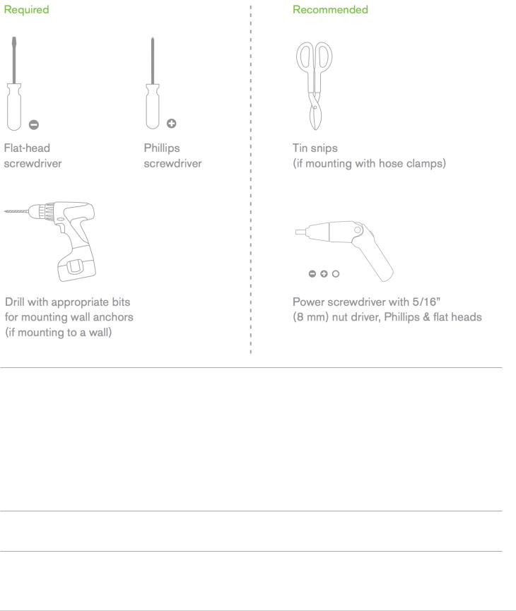
Collect Tools
You will need the following tools to perform an installation:
5
Collect Additional Hardware for Installation
You will need the following tools to perform an installation:
•Network cables with RJ45 connectors long enough for your particular mounting location
•802.3af or 802.3at PoE power source (either PoE switch or Meraki PoE Injector)
•Connection to the internet (if you are setting up your MR74 as a gateway to the internet)
•Appropriately sized metal straps (if mounting to a pole larger than 3.9” in diameter)
•Specialized mounting hardware if mounting to surface other than wood, stucco or stone
Installation Instructions
Choose Your Mounting Location
A good mounting location is important to getting the best performance out of your MR74 access point. Keep the following in mind:
6
1.The device should have unobstructed line of sight to most coverage areas.
2.Power over Ethernet supports a maximum cable length of 300 ft (100 m).
3.If being used in a mesh deployment, the MR74 should have line of sight to at least two other Meraki devices.
4.The antennas should be as unobstructed as possible. Make sure that there is clearance around the MR74 for installation of all of your chosen antennas.
Install the MR74
For most mounting scenarios, the MR74 mount cradle provides a quick, simple, and flexible means of mounting your device. The installation should be done in two steps. First, install the mount cradle to your selected location. Then, attach the MR74 to the mount cradle.
Remove the Mount Plate from the Access Point
Before installing the mount plate, you must remove it from the back of the access point.
1.Unscrew the mount plate attachment screw.
2.Lift the mount plate release tab upwards.
3.While holding the mount plate release tab up, slide the mount plate off the access point in the direction shown below.
Attach the mount cradle
The MR74 mount plate can be used to install your access point in a wide range of scenarios.
Wall or Solid Ceiling Mount Using mount cradle
Using included wall anchors and screws, attach the mount plate to your mounting wall or ceiling.
It is recommended that the MR74 be mounted to a wall or solid ceiling using the mount plate for physical security reasons.
Pole Mount Using Mount Plate
Use the included mounting straps to mount the AP to a pole less than 3.9” in diameter. Thread the mounting straps through the mounting strap slots to secure the mount plate in a horizontal or vertical orientation.
Attach Grounding Strap
Connect one end of grounding strap to grounding post with included screw and washer. Securely attach the other end nearby metal structure.
7
Loading...