

Page 1

Cisco Catalyst 6500-E Series Switch and Cisco Catalyst 6807-XL Switch
PFC4 and PFC4XL Installation Note
Contents 2
Product Overview 2
Safety Warnings 2
Parts List 3
Required Tools 3
Installation Guidelines 3
Preparing the Supervisor Engine 4
Installing a Policy Feature Card 5
Verifying the Policy Feature Card Installation 8
Removing a Policy Feature Card 9
Applying the Label to the Supervisor Engine 10
Troubleshooting 10
Related Documentation 11
Obtaining Documentation and Submitting a Service Request 12
Page 2
Revised: April 7, 2014, OL-31788-01
Contents
This document describes how to install and uninstall the Policy Feature Card 4 (PFC4) and Policy Feature Card 4XL (PFC4XL) on
Cisco Supervisor Engine 2T.
Product Overview
Product numbers: VS-F6K-PFC4=, and VS-F6K-PFC4XL=.
Policy Feature Card 4 (VS-F6K-PFC4=) and Policy Feature Card 4XL (VS-F6K-PFC4XL=) can be installed on the following Cisco
Supervisor Engine 2T models:
• Cisco Supervisor Engine 2T-10GE (model number VS-S2T-10G)—Shipped with factory-installed Policy Feature Card 4.
• Cisco Supervisor Engine 2T-10GE (model number VS-S2T-10G-XL)—Shipped with factory-installed Policy Feature Card
4XL.
Note
To upgrade from VS-S2T-10G to VS-S2T-10G-XL, remove VS-F6K-PFC4= from the corresponding
supervisor engine and install VS-F6K-PFC4XL=.
Cisco Supervisor Engine 2T is shipped with a 2-GB DRAM module by default. Although not mandatory,
we recommend that you install a second 2-GB DRAM module when installing VS-F6K-PFC4XL=. For
installation instructions, see the Installation Note for the Supervisor Engine 2T DRAM Memory on
Cisco.com.
Safety Warnings
Safety warnings appear throughout this publication in procedures that may harm you if you perform them incorrectly. A warning
symbol precedes each warning statement. The warnings below are general warnings that are applicable to the entire publication.
Warning
IMPORTANT SAFETY INSTRUCTIONS
This warning symbol means danger. You are in a situation that could cause bodily injury. Before you
work on any equipment, be aware of the hazards involved with electrical circuitry and be familiar with
standard practices for preventing accidents. Use the statement number provided at the end of each warning
to locate its translation in the translated safety warnings that accompanied this device. Statement 1071
SAVE THESE INSTRUCTIONS
Warning
2
This unit is intended for installation in restricted access areas. A restricted access area can be accessed
only through the use of a special tool, lock and key or other means of security. Statement 1017
Page 3
Warning
Only trained and qualified personnel should be allowed to install, replace, or service this equipment.
Statement 1030
Warning
Warning
Hazardous voltage or energy is present on the backplane when the system is operating. Use caution when
servicing. Statement 1034
Blank faceplates and cover panels serve three important functions: they prevent exposure to hazardous
voltages and currents inside the chassis; they contain electromagnetic interference (EMI) that might disrupt
other equipment; and they direct the flow of cooling air through the chassis. Do not operate the system
unless all cards, faceplates, front covers, and rear covers are in place. Statement 1029
Parts List
The following parts are available in both the Policy Feature Card 4 kit and the Policy Feature Card 4XL kit.
One VS-F6K-PFC4= or VS-F6K-PFC4XL= policy feature card.
•
One packet of labels.
•
One disposable grounding wrist strap.
•
One bag of mounting screws.
•
Required Tools
These tools are required to perform the installation or removal of the Policy Feature Card 4 or Policy Feature Card 4XL:
Antistatic mat or foam pad to support the removed supervisor engine.
•
3/16-inch flat-blade screwdriver for the captive installation screws on the supervisor engine.
•
Number 1 Phillips screwdriver for the screws and cap nuts that fasten the policy feature card to the supervisor engine.
•
Your own ESD-prevention equipment or the disposable grounding wrist strap included with all upgrade kits, field-replaceable
•
units (FRUs), and spares.
Installation Guidelines
Observe the following cautionary guidelines when installing the Policy Feature Card 4 or Policy Feature Card 4XL:
3
Page 4
Caution
If you have redundant supervisor engines, you must install the same policy feature card on each
•
supervisor engine. The hardware on both the supervisor engines in a single chassis must be identical.
You must shut down the switch to install the policy feature card, even if you have redundant supervisor
•
engines.
Ensure that the policy feature card is securely seated before you install and tighten the cap nut and
•
the securing screws. If you use the screws to forcibly seat the policy feature card, the card might
warp.
You must use all the screws. The screws provide grounding between the policy feature card and the
•
supervisor engine. Failure to use and tighten all screws will invalidate the safety approval and pose
a fire and electrical hazard.
Use care not to damage the connectors on the supervisor engine. If you damage a connector, you
•
will have to return the supervisor engine to Cisco for repair.
Always use an ESD wrist strap when handling modules or coming into contact with internal
•
components.
Preparing the Supervisor Engine
To prepare Cisco Supervisor Engine 2T before you install or remove Policy Feature Card 4 or Policy Feature Card 4XL, perform
these steps:
Before You Begin
Always use an ESD wrist strap when handling modules or coming into contact with internal components.Caution
Procedure
Step 1
Step 2
Step 3
Step 4
Upload the current configuration to a server and save the running configuration on any modules running Cisco IOS software.
Note
Shut down the switch.
Remove the supervisor engine from the chassis.
For removal instructions, see the Catalyst 6500 Series Switch Module Installation Guide on Cisco.com.
Place the supervisor engine on an antistatic mat or foam.
Performing this step saves time when bringing the module back online. You can recover the configuration by
downloading it from the server to the nonvolatile memory of the supervisor engine. For more information, refer
to Chapter 26, "Working with Configuration Files" in the Catalyst 6500 Series Software Configuration Guide on
Cisco.com.
What to Do Next
Install or remove the policy feature card.
4
Page 5

Installing a Policy Feature Card
This topic describes how to install Policy Feature Card 4XL (VS-F6K-PFC4XL=).
The procedure to install Policy Feature Card 4, and Policy Feature Card 4XL is the same.Note
Before You Begin
Refer to the topics Installation Guidelines, on page 3 and Preparing the Supervisor Engine, on page 4.
Procedure
Step 1
Step 2
Remove the policy feature card from its antistatic bag.
Insert the front edge of the policy feature card under the EMI gasket on the supervisor engine.
Figure 1: Inserting the PFC4XL Under the EMI Gasket
Caution
Use care not to damage the connectors on the supervisor engine. If you damage a connector, you will have to
return the supervisor engine to Cisco for repair.
5
Page 6

Step 3
Align the policy feature card with the male standoffs on the supervisor engine, and carefully seat the policy feature card
onto the supervisor engine.
Figure 2: Male Standoff Location on Cisco Supervisor Engine 2T
Step 4
Caution
Use care not to damage the connectors on the supervisor engine. If you damage a connector, you will
•
have to return the supervisor engine to Cisco for repair.
Ensure that the policy feature card is securely seated before you install and tighten the cap nuts and the
•
securing screws. If you use the screws to forcibly seat the policy feature card, the card might warp.
Using your thumbs, apply pressure at the locations shown in the following figure to ensure that the policy feature card is
securely seated on the supervisor engine.
Figure 3: Seating the PFC4XL on the Supervisor Engine
6
Page 7
Step 5
Use a Phillips-head screwdriver to install the supplied screws and cap nuts that secure the VS-F6K-PFC4XL= to the
Supervisor Engine 2T.
Figure 4: Installing the Supplied Screws
Caution
You must use all the screws. The screws provide grounding between the policy feature card and the supervisor
engine. Failure to use and tighten all screws will invalidate the safety approval and pose a fire and electrical
hazard.
Use the supplied screws and cap nuts to secure the policy feature card to the supervisor engine.Note
Step 6
Install the supervisor engine in the switch chassis.
Refer to the Catalyst 6500 Series Switch Module Installation Guide for installation instructions.
What to Do Next
1
If you are installing a policy feature card on a redundant supervisor engine, repeat the procedure for removing the supervisor
engine and install the same policy feature card there as well. See topic Preparing the Supervisor Engine, on page 4.
2
Power up the switch.
7
Page 8

3
Verify the installation procedure. See Verifying the Policy Feature Card Installation, on page 8.
Verifying the Policy Feature Card Installation
This section describes how to verify the policy feature card installation. This applies to the Cisco IOS software on the supervisor
engine and the Multilayer Switch Feature Card 5 (MSFC5):
Verify that the switch is online. This indicates that the system acknowledges the new module and has brought it online. Enter the
show module command in the privileged EXEC mode.
The following is the show module command output of a Cisco Catalyst 6807-XL Switch. Here, the supervisor engines have been
upgraded from VS-S2T-10G to VS-S2T-10G-XL by installing the VS-F6K-PFC4XL= policy feature cards. The Sub-Module section
in the output shows that two VS-F6K-PFC4XL= policy feature cards are installed and are working properly (Status is Ok).
C6807-XL.4SUP.VSS# show module
Mod Ports Card Type Model Serial No.
--- ----- -------------------------------------- ------------------ ----------1 20 DCEF2T 4 port 40GE / 16 port 10GE WS-X6904-40G SAL1624E826
3 5 Supervisor Engine 2T 10GE w/ CTS (Acti VS-SUP2T-10G SAL17152F6Q
4 5 Supervisor Engine 2T 10GE w/ CTS (CSSO VS-SUP2T-10G SAL17152F7C
5 4 Network Analysis Module 3 WS-SVC-NAM-3-K9 SAL1530KNW3
6 48 CEF720 48 port 1000mb SFP WS-X6848-SFP SAL1533MHD4
7 48 CEF720 48 port 10/100/1000mb Ethernet WS-X6848-GE-TX SAL1534N50G
Mod MAC addresses Hw Fw Sw Status
--- ---------------------------------- ------ ------------ ------------ ------1 1cdf.0f9b.df26 to 1cdf.0f9b.df39 1.0 12.2(50r)SYL 15.1(2)SY2 Ok
3 2c54.2dc4.a0a5 to 2c54.2dc4.a0ac 1.5 12.2(50r)SYS 15.1(2)SY2 Ok
4 2c54.2dc3.7499 to 2c54.2dc3.74a0 1.5 12.2(50r)SYS 15.1(2)SY2 Ok
5 e8b7.4828.fc80 to e8b7.4828.fc8f 1.0 12.2(50r)SYL 15.1(2)SY2 Ok
6 0007.7d90.5fb8 to 0007.7d90.5fe7 1.0 12.2(18r)S1 15.1(2)SY2 Ok
7 0007.7d90.6f78 to 0007.7d90.6fa7 1.0 12.2(18r)S1 15.1(2)SY2 Ok
Mod Sub-Module Model Serial Hw Status
---- --------------------------- ------------------ ----------- ------- ------1 Distributed Forwarding Card WS-F6K-DFC4-EXL SAL1532M1VE 1.0 Ok
3 Policy Feature Card 4 VS-F6K-PFC4XL SAL1422005E 1.0 Ok
3 CPU Daughterboard VS-F6K-MSFC5 SAL17142D69 2.0 Ok
4 Policy Feature Card 4 VS-F6K-PFC4XL SAL142502KP 1.0 Ok
4 CPU Daughterboard VS-F6K-MSFC5 SAL171424F1 2.0 Ok
5/0 NAM Application Processor SVC-APP-PROC-1 SAL1530KLVV 1.0 Ok
6 Distributed Forwarding Card WS-F6K-DFC4-AXL SAL1533MDL3 1.0 Ok
7 Distributed Forwarding Card WS-F6K-DFC4-AXL SAL1535NTGL 1.1 Ok
Base PID:
Mod Model Serial No.
---- ----------- ---------5 WS-SVC-APP-HW-1 SAL1530KNW3
Mod Online Diag Status
---- ------------------1 Pass
3 Pass
4 Pass
5 Pass
5/0 Pass
6 Pass
7 Pass
C6807-XL.4SUP.VSS#
If the installation is not successful, the system will not boot. For more information, see Troubleshooting, on page 10.
8
Page 9

Removing a Policy Feature Card
This topic describes how to remove Policy Feature Card 4 (VS-F6K-PFC4=).
The procedure to remove Policy Feature Card 4, and Policy Feature Card 4XL is the same.Note
Before You Begin
Refer to the topics Installation Guidelines, on page 3 and Preparing the Supervisor Engine, on page 4.
Procedure
Step 1
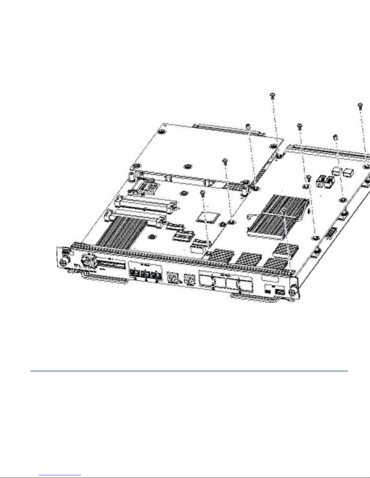
Remove the nine securing screws and two cap nuts, and set them aside.
Use the supplied screws and cap nuts when securing a policy feature card to the supervisor engine.
Figure 5: Removing Securing Screws and Cap Nuts
Caution
Use care not to damage the connectors on the supervisor engine. If you damage a connector, you will have to
return the supervisor engine to Cisco for repair.
9
Page 10

Step 2
Hold the right edge of the card with your right hand and the rear left corner with your left hand. Gently lift the card with
both hands simultaneously and remove the card from the supervisor engine.
Figure 6: Removing PFC4
Step 3
Place the card on an antistatic mat or antistatic foam pad.
Applying the Label to the Supervisor Engine
The policy feature card kit includes a label. Apply the label to the upper-left corner of the supervisor engine front panel.
Figure 7: Applying the Label
Troubleshooting
The following table provides troubleshooting tips that you can use if the policy feature card installation is not successful:
Table 1: Troubleshooting
The supervisor engine fails online diagnostics.
Severity—Low
10
SolutionProblem
Remove the supervisor engine from the chassis and make sure
that all the securing screws and cap nuts are tight. See Figure
4: Installing the Supplied Screws, on page 7
Page 11
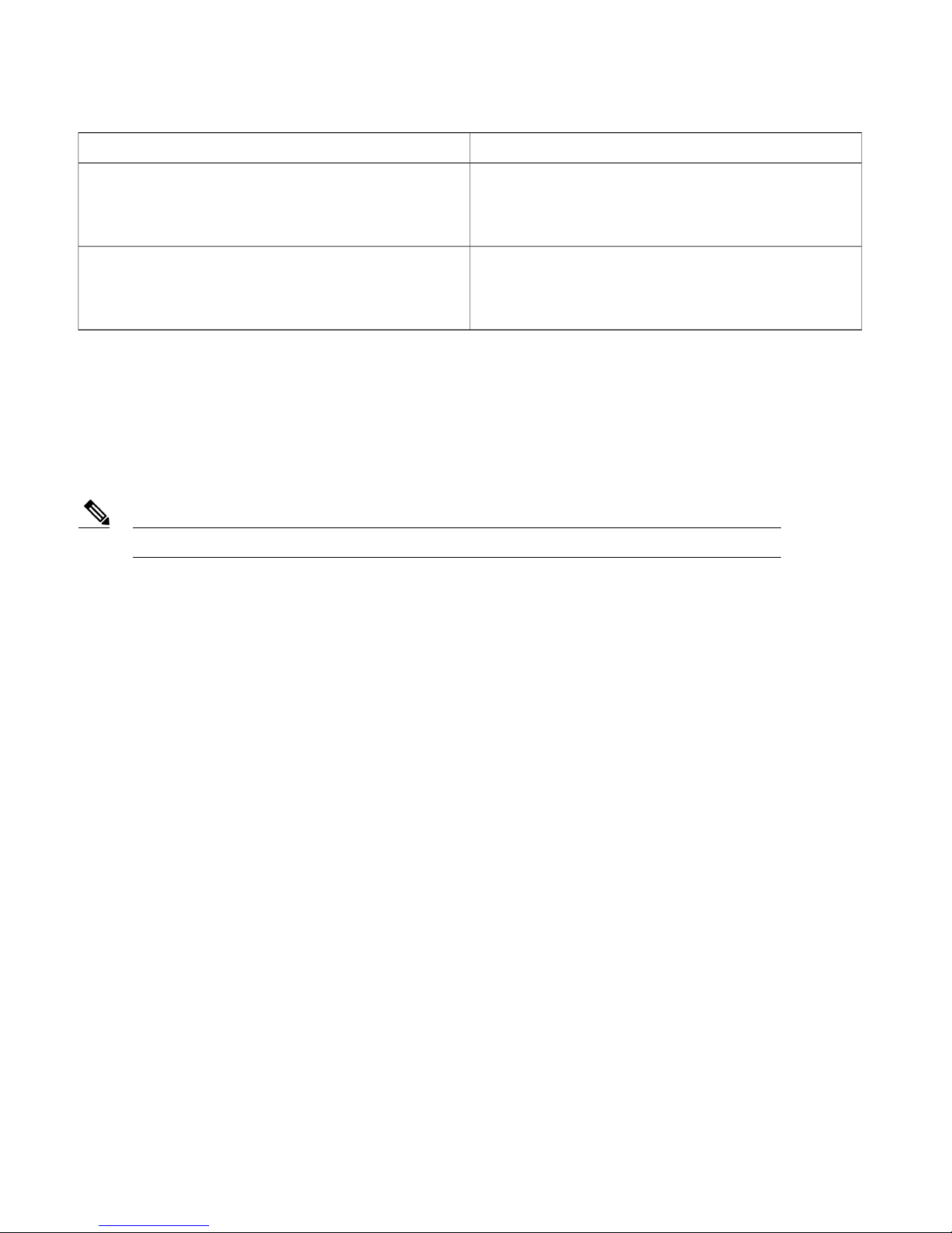
SolutionProblem
The supervisor engine experiences a partial boot up, or a
software-forced reset, or boots to ROMMON.
Severity—Medium
The supervisor engine does not boot up (no power to supervisor
engine, no console prompt, no STATUS LED).
Severity—High
If these solutions do not resolve the corresponding issue, contact a Cisco customer service representative for instructions. For
information on obtaining technical assistance, see the topic Obtaining Documentation and Submitting a Service Request, on page
12.
Remove the supervisor engine from the chassis and make sure
that all securing screws and cap nuts are tight. Check if the
BOOT variable is correct, and the Cisco IOS image is available.
Remove the supervisor engine from the chassis and reseat the
RP memory modules.
Related Documentation
Note
For additional information on Cisco Catalyst 6807-XL switches and command-line interface (CLI) commands, refer to the following
publications located at: http://www.cisco.com/go/cat6800_docs:
Before installing or upgrading, refer to the Release Notes for Cisco IOS Release 15.1SY.
Regulatory Compliance and Safety Information for the Catalyst 6880-X and 6807-XL Switches
•
Cisco Catalyst 6807-XL Switch Hardware Installation Guide
•
Release 15.1SY Supervisor Engine 2T Software Configuration Guide
•
Cisco IOS 15.1SY Configuration Guides
•
For additional information on Catalyst 6500 series switches and command-line interface (CLI) commands, refer to the following
publications located at http://www.cisco.com/go/cat6500_docs:
Regulatory Compliance and Safety Information for the Catalyst 6500 Series Switches
•
Catalyst 6500 Series Switch Installation Guide
•
Catalyst 6500 Series Switch Module Installation Guide
•
Catalyst 6500 Series Switch Software Configuration Guide
•
Catalyst 6500 Series Switch Command Reference
•
Catalyst 6500 Series Switch Cisco IOS Software Configuration Guide
•
Catalyst 6500 Series Switch Cisco IOS Command Reference
•
Catalyst 6500 Series System Message Guide
•
11
Page 12

Obtaining Documentation and Submitting a Service Request
For information on obtaining documentation, submitting a service request, and gathering additional information, see the monthly
What's New in Cisco Product Documentation, which also lists all new and revised Cisco technical documentation, at:
http://www.cisco.com/en/US/docs/general/whatsnew/whatsnew.html
Subscribe to the What's New in Cisco Product Documentation as a Really Simple Syndication (RSS) feed and set content to be
delivered directly to your desktop using a reader application. The RSS feeds are a free service and Cisco currently supports RSS
version 2.0.
12
Page 13

Cisco and the Cisco logo are trademarks or registered trademarks of Cisco and/or its affiliates in the U.S. and other countries. To view a list of Cisco trademarks, go to this URL: http://
www.cisco.com/go/trademarks. Third-party trademarks mentioned are the property of their respective owners. The use of the word partner does not imply a partnership
relationship between Cisco and any other company. (1110R)
©
2014 Cisco Systems, Inc. All rights reserved.
Page 14

Cisco Systems, Inc.
San Jose, CA 95134-1706
USA
Cisco has more than 200 offices worldwide. Addresses, phone numbers, and fax numbers are listed on the
Cisco Website at www.cisco.com/go/offices.
Cisco Systems (USA) Pte. Ltd.
Singapore
Europe HeadquartersAsia Pacific HeadquartersAmericas Headquarters
Cisco Systems International BV
Amsterdam, The Netherlands
 Loading...