

Cisco VG400 series, SM-X-16FXS/2FXO, SM-X-8FXS/12FXO, SM-X-72FXS, SM-X-24FXS/4FXO Hardware Installation Manual
Page 1

Cisco VG400 Voice Gateway Hardware Installation Guide
First Published: 2018-11-30
Americas Headquarters
Cisco Systems, Inc.
170 West Tasman Drive
San Jose, CA 95134-1706
USA
http://www.cisco.com
Tel: 408 526-4000
800 553-NETS (6387)
Fax: 408 527-0883
Page 2

©
2018 Cisco Systems, Inc. All rights reserved.
Page 3

CHAPTER 1
Introduction to Cisco VG400 Voice Gateway
Cisco medium-density Analog Voice Gateway provide enterprises, managed services providers, and service
providers the ability to directly connect public-switched telephone networks (PSTNs) and existing telephony
equipment to Cisco 4000 Series Integrated Services Routers. These FXS and FXO ports provide Dual-Tone
Multifrequency (DTMF) detection, voice compression and decompression, call progress tone generation,
Voice Activity Detection (VAD), echo cancellation, and adaptive jitter buffering. Cisco VG400 Voice Gateway
is a medium-density analog voice gateway. It is an intermediate path that enables TDM to IP transition.
The Cisco VG400 Voice Gateway supports the following interfaces:
• Two RJ45 Gigabit Ethernet (GE) ports
• One RJ45 Console Port
• One USB 2.0 Port
• LED for System, GE Port, and Console Port Status
• Features and Benefits of Cisco VG400 Voice Gateway, on page 1
• Cisco VG400 Voice Gateway Chassis, on page 3
• LED Indicators, on page 4
• Slot, Bay, and Ports, on page 5
• Technical and Compliance Specifications, on page 7
• Platform and Software Requirements, on page 9
Features and Benefits of Cisco VG400 Voice Gateway
Cisco VG400 Voice Gateway provides VoIP connectivity to analog devices, such as analog desk phones,
analog conference room phones, fax machines, and modems. Cisco 400 Voice Gateway provides several
improvements from the previous high-density analog and digital extension modules (EVMs), in the following
ways:
• On-board Digital Signal Processor (DSP)—The FXO and FXS ports contain an onboard DSP and
don’t require the router to have a dedicated packet voice DSP module (PVDM) on the motherboard. The
DSP on the voice module is necessary for the voice features. It also provides for echo cancellation of up
to 128-ms echo-tail length for demanding network conditions.
• FXS-E (extended loops) support—FXS ports on the new modules support FXS-E with the following
details:
• Higher loop current (35 mA) to accommodate specialty phones
• Longer loop length for loops with 26 AWG wire, up to 11,000 feet (3400 meters)
Cisco VG400 Voice Gateway Hardware Installation Guide
1
Page 4

Analog Phone Connectivity
In addition to these features, Cisco 400 Voice Gateway also supports the following features:
Introduction to Cisco VG400 Voice Gateway
• Higher ringing voltage (65 Vrms, no load)
• FXO failover bypass ports—A failover bypass port, also called a failover trunk bypass, provides a way
to use designated analog phone ports to make phone calls through the PSTN during a power outage.
• Caller line ID
• G.711, G.729a, and G.726
• G722, iLBC, GSMAMR-NB, and Internet Speech Audio Codec (iSAC)
• Fax detection, pass-through, and relay (T.38)
• Modem pass-through
• DTMF detection
• Echo cancellation
• Voice activity detection
• Comfort noise generation
• Real-Time Control Protocol (RTCP)
• Acoustic shock protection
• Real-Time Transport Protocol (RTP)
• RFC 4733 Digit Relay
• Noise reduction is on the roadmap
The FXS features include:
• Support for either FXS or DID functionality
• Message-Waiting Indicator (MWI)
• Cable detection: GR909 line test
• The FXO features include:
• Support for both ground-start and loop-start modes
• Support for FXO CAMA signaling type
• Call Detail Record (CDR) information
• Support for interworking with Cisco Unified Communications Manager (Skinny Client Control Protocol
[SCCP]), H.323, Session Initiation Protocol (SIP), and Media Gateway Control Protocol (MGCP) 0.1
• Cable detection
• Overload protection
Analog Phone Connectivity
Cisco 400 Voice Gateway are ideal for analog phone deployments ranging from centralized to sparsely
concentrated or distributed topologies. Cisco 400 Voice Gateway offer many supplementary analog calling
features, depending on the call control and signaling type used. All supplementary analog features are supported
through the FXS and FXO ports. The analog interface on Cisco 400 Voice Gateway also supports Feature
Access Codes (FACs) for invoking supplementary services.
Fax and Modem Connectivity
FXS ports on Cisco 450 Voice Gateway support fax machines and modems. When using fax machines, the
gateways support T.38 fax relay and fax pass-through. T.38 fax relay technologies allow transfer of faxes
Cisco VG400 Voice Gateway Hardware Installation Guide
2
Page 5
Introduction to Cisco VG400 Voice Gateway
across the network with high reliability using less bandwidth than a voice call. All modems can be connected
to the Cisco VG Series Gateways and are transferred over the network using modem pass-through.
Protocols Supported
The voice gateways support the following protocols:
• SCCP
• H.323v4
• MGCP
• SIP
• Real-Time Transport Protocol (RTP)
• Secure Real-Time Transport Protocol (SRTP)
• Trivial File Transfer Protocol (TFTP)
• HTTP server
• Simple Network Management Protocol (SNMP)
• Telnet
• Dynamic Host Configuration Protocol (DHCP)
• DNS
• Cisco Unified Communications Manager or Cisco Unified Communications Manager Express redundancy
support using Hot Standby Router Protocol (HSRP)
• Call survivability: MGCP failover to an H.323 connection to the Survivable Remote Site Telephony
(SRST) router
• T.38 fax relay and modem pass-through
• Codec support: G.711, G.729. G.729a will be used if the gateway does not support G729 annex b
• RADIUS and TACACS+ for Telnet and authorization
Protocols Supported
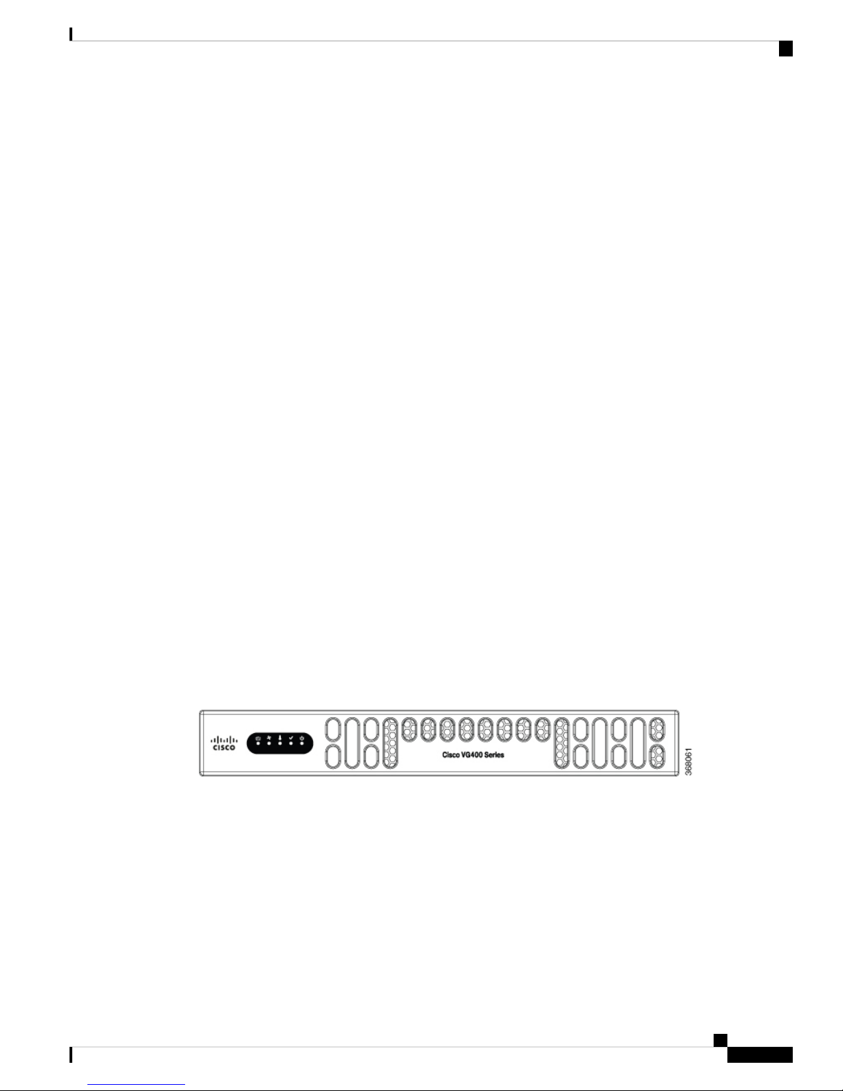
Cisco VG400 Voice Gateway Chassis
The following figures show the front and back panels of the Cisco VG400 Voice Gateway Chassis:
Figure 1: Front panel of the Cisco VG400 Voice Gateway
Cisco VG400 Voice Gateway Hardware Installation Guide
3
Page 6
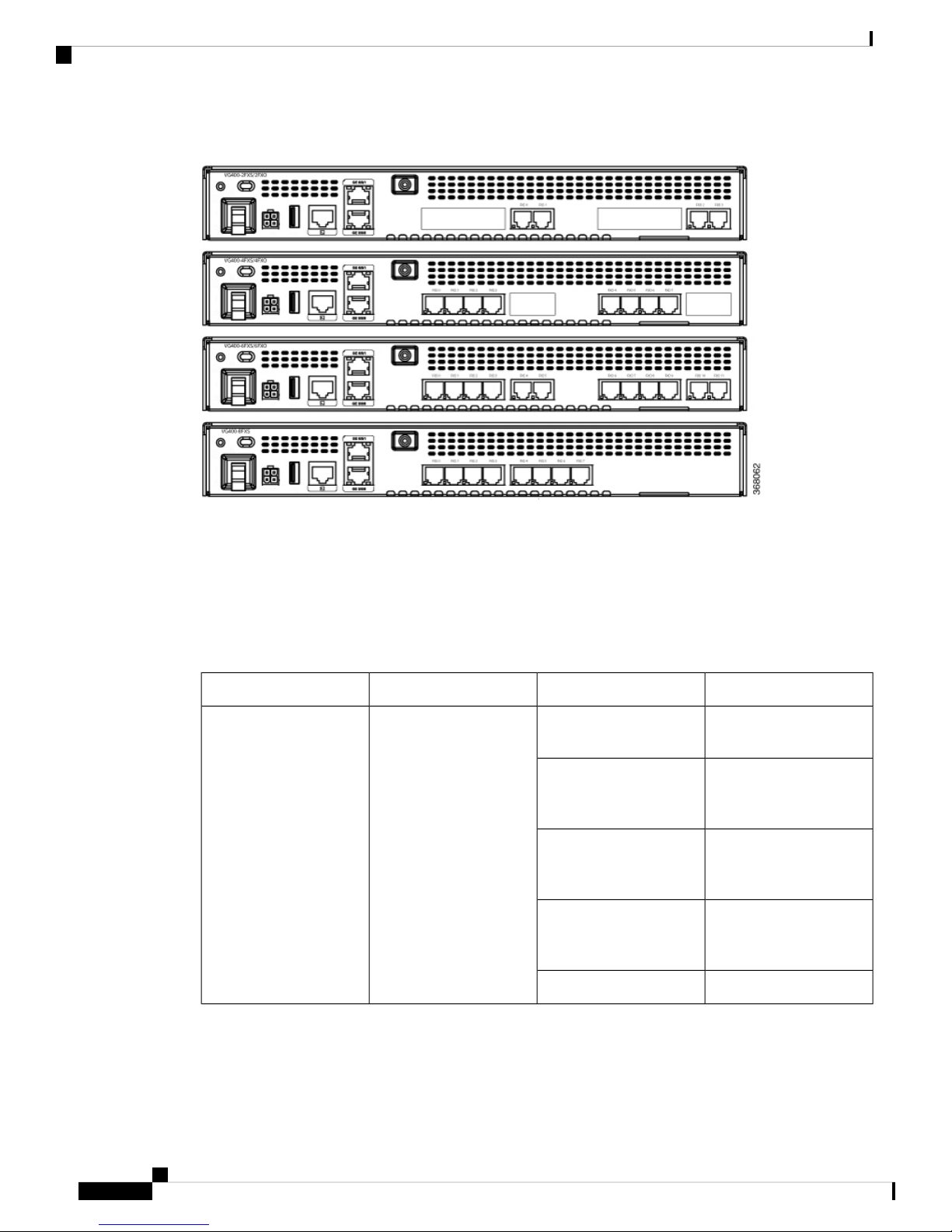
LED Indicators
Introduction to Cisco VG400 Voice Gateway
Figure 2: Back Panel of the VG400 Voice Gateway
LED Indicators
The following table summarizes the LED indicators that are located in the bezel side of Cisco VG400 Voice
Gateway:
Table 1:
GreenSystem PowerPWR
Green blinking
Amber
Amber blinking
DescriptionColorRepresentsLED
System power is on and
functions correctly
System power is on and
in the process of shutting
down
System power is up, but
low level initialization has
failed
System power is up, but
the system has failed to
come out of reset
System power is offOff
Cisco VG400 Voice Gateway Hardware Installation Guide
4
Page 7

Introduction to Cisco VG400 Voice Gateway
Slot, Bay, and Ports
DescriptionColorRepresentsLED
System StatusSTAT
Amber
SystemFlash statusFLASH
Blinking Green
Solid GreenTemperature StatusTEMP
Amber
System operates normallySolid Green
BIOS/RUMMON bootingBlinking Amber
BIOS/ROMMON has
completed booting, and
system is at the
ROMMON prompt or the
booting platform software
Compact flash/eUSB flash
is present and is currently
being accessed.
Note Do not remove the
flash device while the
system is powered on.
All the temperature
sensors in the system are
within the acceptable
range
One or more temperature
sensors in the system are
outside the acceptable
range
Slot, Bay, and Ports
The FXO port is used to connect to PBX or key systems, or to provide off-premises connections to the PSTN.
It supports battery reversal detection and caller ID. The FXO port is also used to connect to analog Centralized
Automatic Message Accounting (CAMA) trunks to provide dedicated E-911 service (only in North America).
The FXS port is used to connect analog phones, modems, fax machines, and speaker phones to an enterprise
IP voice system, to use them as extensions to your Cisco or third-party IP call-control system. Having these
Off
Fan statusFAN
Amber
Blinking Amber
Temperature is not being
monitored
All the fans are operatingGreen
One of the fans has
stopped working
Two or more fans have
stopped working, or the
fan tray has been removed
Fans are not monitoredOff
Cisco VG400 Voice Gateway Hardware Installation Guide
5
Page 8
Slot, Bay, and Ports
devices tightly integrated with the IP-based phone system is advantageous for increased manageability,
scalability, and cost-effectiveness. The Direct Inward Dialing (DID) port is used to provide off-premises DID
connection from the central office. It serves only incoming calls from the PSTN. The Caller ID feature is not
supported in DID mode.
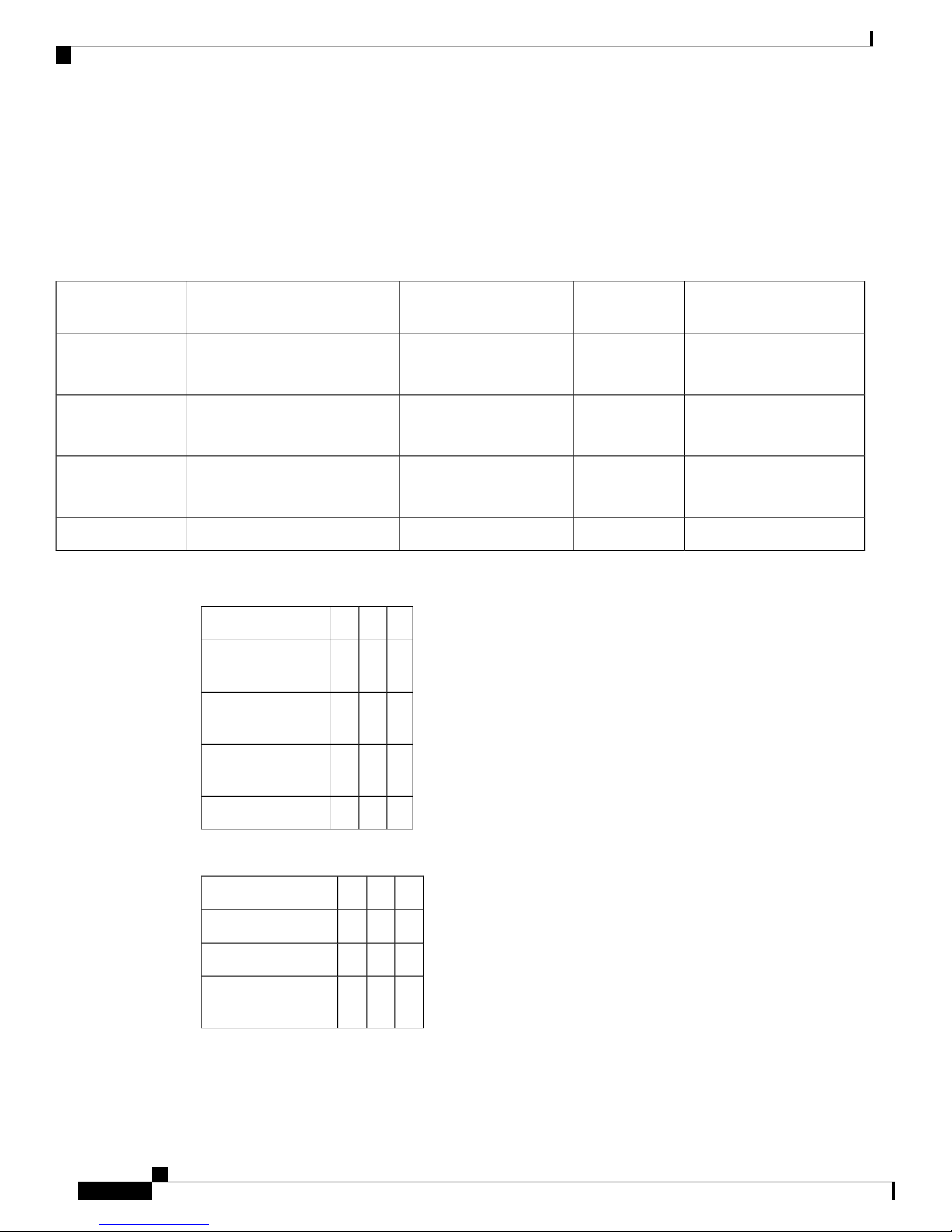
The following table provides information about Cisco 400 Voice Gateway SKU:
Table 2: Cisco 400 Voice Gateway FXS-E/DID, REN, Failed-over Port Support
Introduction to Cisco VG400 Voice Gateway
Maximum Number or RENsMaximum Number of FXS-E PortsInterface
102VG400-2FXS/2FXO
124VG400-4FXS/4FXO
126VG400-6FXS/6FXO
Table 3: Slot, bay, and port information for Cisco VG400 FXS Port
PortBaySlotInterface
0-1102FXS/2FXO
0/1/0-1
0-3104FXS/4FXO
0/1/0-3
Number of Failed-over PortsRJ-11
Connectors
2FXS: 1x2
FXO: 1x2
4FXS: 1x4
FXO: 1x4
6FXS: 1x2 1x4
FXO: 1x2 1x4
—FXS: 1x4 1x4168VG400-8FXS
0-5106FXS/6FXO
0/1/0-5
0-7108FXS
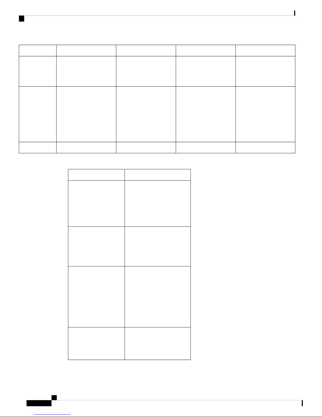
Table 4: Slot, bay, and port information for Cisco VG400 FXO Port
PortBaySlotInterface
2-3102FXS/2FXO 0/1/2-3
3-7104FXS/4FXO 0/1/3-7
6-11106FXS/6FXO
0/1/6-11
Cisco VG400 Voice Gateway Hardware Installation Guide
6
Page 9

Introduction to Cisco VG400 Voice Gateway
Technical and Compliance Specifications
The following table details the technical specifications of Cisco VG400 Voice Gateway.
Table 5: Cisco VG400 Voice Gateway Technical Specifications
Physical
Technical and Compliance Specifications
SM-X-72FXSSM-X-24FXS/4FXOSM-X-16FXS/2FXOSM-X-8FXS/12FXODescription
Dimensions (H
x W x D)
Power
AC power
Off-hook loop
current
Operating
temperature
Nonoperating
temperature
FXS loop
resistance
25 mA (maximum) for
short loop-length-port35
mA for long
loop-length-port
32 o to 104 o F (0 o to 40 o
C)
-40 o to 158 o F (-40 o to
70 o C)
Up to 600 ohms for short
loop-length-portUp to 1400
ohms for long
loop-length-port
25 mA (maximum) for
short loop-length-port35
mA for long
loop-length-port
32 o to 104 o F (0 o to 40 o
C)
-40 o to 158 o F (-40 o to
70 o C)
Up to 600 ohms for short
loop-length-portUp to 1400
ohms for long
loop-length-port
25 mA (maximum) for
short loop-length-port35
mA for long
loop-length-port
32 o to 104 o F (0 o to 40 o
C)
-40 o to 158 o F (-40 o to
70 o C)
Up to 600 ohms for short
loop-length-portUp to 1400
ohms for long
loop-length-port
1.58 x 15.57 x 7.57 inches1.58 x 7.44 x 7.6 inches1.58 x 7.44 x 7.6 inches1.58 x 7.44 x 7.6 inches
4.94 lb (2.24 kg)2.12 lb (0.96 kg)1.98 lb (0.90 kg)1.90 lb (0.86 kg)Weight
128.16W79.37W70.32W53.55W
10.68A on 12V6.61A on 12V5.86A on 12V4.46A on 12VCurrent
12V from backplane12V from backplane12V from backplane12V from backplaneVoltage
-44V-44V-44V-44VOn-hook voltage
25 mA (maximum) for
short loop-length-port35
mA for long
loop-length-port
32 o to 104 o F (0 o to 40 o
C)
-40 o to 158 o F (-40 o to
70 o C)
Up to 600 ohms for short
loop-length-portUp to 1400
ohms for long
loop-length-port
resistance
REN loading
5 RENs per port
(short-loop-length port)2
RENs per port
(long-loop-length port)
5 RENs per port
(short-loop-length port)2
RENs per port
(long-loop-length port)
Cisco VG400 Voice Gateway Hardware Installation Guide
5 RENs per port
(short-loop-length port)2
RENs per port
(long-loop-length port)
Up to 1400 ohmsUp to 1400 ohmsUp to 1400 ohmsUp to 1400 ohmsDID loop
20, 25, 30, and 50 Hz20, 25, 30, and 50 Hz20, 25, 30, and 50 Hz20, 25, 30, and 50 HzRing frequency
5 RENs per port
(short-loop-length port)2
RENs per port
(long-loop-length port)
7
Page 10
Technical and Compliance Specifications
Introduction to Cisco VG400 Voice Gateway
SM-X-72FXSSM-X-24FXS/4FXOSM-X-16FXS/2FXOSM-X-8FXS/12FXODescription
Impedance
FXS loop length
600c, 600r, 900c, 900r,
complex1, complex2,
complex3, complex4,
complex5, and complex6
Short-loop-length port:
3000 ft (900 m) with 26
AWG, 5500 ft (1700 m)
with 24
AWGLong-loop-length
port: 11,000 ft (3400 m)
with 26 AWG, 18,000 ft
(5500 m) with 24 AWG
600c, 600r, 900c, 900r,
complex1, complex2,
complex3, complex4,
complex5, and complex6
Short-loop-length port:
3000 ft (900 m) with 26
AWG, 5500 ft (1700 m)
with 24
AWGLong-loop-length
port: 11,000 ft (3400 m)
with 26 AWG, 18,000 ft
(5500 m) with 24 AWG
600c, 600r, 900c, 900r,
complex1, complex2,
complex3, complex4,
complex5, and complex6
Short-loop-length port:
3000 ft (900 m) with 26
AWG, 5500 ft (1700 m)
with 24
AWGLong-loop-length
port: 11,000 ft (3400 m)
with 26 AWG, 18,000 ft
(5500 m) with 24 AWG
The following table details the compliance specifications of Cisco VG400 Voice Gateway.
DescriptionCompliance Specification
Safety
• UL 60950-1
• CAN/CSA C22.2 No.
60950-1
• EN 60950-1
• AS/NZS 60950-1
• IEC 60950-1
600c, 600r, 900c, 900r,
complex1, complex2,
complex3, complex4,
complex5, and complex6
Short-loop-length port:
3000 ft (900 m) with 26
AWG, 5500 ft (1700 m)
with 24
AWGLong-loop-length
port: 11,000 ft (3400 m)
with 26 AWG, 18,000 ft
(5500 m) with 24 AWG
Category 3 and Category 5Category 3 and Category 5Category 3 and Category 5Category 3 and Category 5Cables
Telecom
EMC
Immunity
• TIA/EIA/IS-968
• CS-03
• TBR21 (FXO)
• ES 201 970 (FXS)
• S002, S003
• 47 CFR, Part 15
• CES-003 Issue 4
• EN55022 Class A/B
• CISPR22 Class A/B
• AS/NZS 3548 Class A
• VCCI V-3
• CNS 13438
• EN 300-386
• EN 55024, CISPR 24
• EN50082-1
• EN 61000-6-1
• EN300-386
Cisco VG400 Voice Gateway Hardware Installation Guide
8
Page 11

Introduction to Cisco VG400 Voice Gateway
Platform and Software Requirements
Cisco 400 Voice Gateway is supported on IOS XE Release16.10.1. The ports provide gateway services for
Cisco Unified Communications using Cisco Unified Communications Manager or Cisco Unified
Communications Manager Express. The following list provides information about the software version that
is compatible with the FXO and FXS ports:.
• CUCM: 12.5.1, 12.0.1su2 and 12.0.1 (with device pack)
• IOS XE: Version 16.10.1 and later
Configuration Methods
After Cisco 400 Voice Gateway is operational, use the procedures in Cisco 400 Voice Gateway Software
Configuration Guide to configure the specific services and functions or to make changes to an existing
configuration.
There are multiple methods for configuring Cisco 400 Voice Gateways:
Platform and Software Requirements
• System configuration dialog
• Configuration mode: Cisco IOS software CLI
• Setup command facility: Remote configuration through a LAN
• SNMP-based application: CiscoView or HP OpenView
• HTTP-based configuration server: Provides access to the CLI from a web browser
Cisco VG400 Voice Gateway Hardware Installation Guide
9
Page 12

Configuration Methods
Introduction to Cisco VG400 Voice Gateway
Cisco VG400 Voice Gateway Hardware Installation Guide
10
Page 13

CHAPTER 2
Planning Your Installation
This chapter provides preinstallation information, such as recommendations and requirements that must be
met before installing Cisco VG400 Voice Gateway. Before you begin, inspect all items for shipping damage.
If anything appears to be damaged or if you encounter problems installing or configuring the Voice Gateway,
contact the customer service. Warranty, service, and support information is included in the Hardware Quick
Start guide that is shipped with your product. See the following sections to prepare for installation:
• Location and Mounting Requirements, on page 11
• Temperature Control and Ventilation, on page 12
• Rack requirements, on page 12
• Access to Chassis, on page 12
• Power Source and Supply, on page 13
• Network Cabling Considerations, on page 13
• Interference Considerations , on page 14
• Required tools and equipment for installation, on page 15
• Site Log, on page 15
• Installation Checklist, on page 16
Location and Mounting Requirements
The three mounting possibilities for your Cisco VG400 Voice Gateway are as follows:
• Rack-mount
• Wall-mount
The mounting location must provide the following:
• Access to the chassis.
• Access to a suitable power source.
• Access to an appropriate earth ground.
• Allowance for adequate heat dissipation and airflow around the chassis.
Bench Mounted
The installation location (room, closet, or cabinet) for the Cisco VG400 Voice Gateway should always be
well ventilated and provide adequate air circulation to ensure proper cooling. The room temperature should
be maintained between 32 to 104°F (0 to 40°C).
Cisco VG400 Voice Gateway Hardware Installation Guide
11
Page 14

Temperature Control and Ventilation
Note
The Cisco VG400 Voice Gateway chassis is designed for back and sides-to-front airflow.
Temperature Control and Ventilation
The installation location (room, closet, or cabinet) for the Cisco VG400 Voice Gateway should always be
well ventilated and provide adequate air circulation to ensure proper cooling. The room temperature should
be maintained between 32 to 104°F (0 to 50°C).
Note
The Cisco VG400 Voice Gateway chassis is designed for back and sides-to-front airflow.
Rack requirements
Planning Your Installation
The following information can help you plan your equipment rack configuration:
• Allow clearance around the rack for maintenance.
• Enclosed racks must have adequate ventilation. Ensure that the rack is not congested, because the hardware
generates heat. An enclosed rack should have louvered sides and a fan to provide cooling air. Heat
generated by equipment at the bottom of the rack can be drawn upward into the intake ports of the
equipment above it.
• When mounting a chassis in an open rack, ensure that the rack frame does not block the intake or exhaust
ports. If the chassis is installed on slides, check the position of the chassis when it is seated in the rack.
If the Cisco VG400 Voice Gateway is installed in an enclosed rack with a ventilation fan at the top, make
sure that heated air drawn upward from other equipment does not prevent adequate cooling.
Note
Enclosed racks must have adequate ventilation. An enclosed rack should never be overcrowded and should
have louvers and a fan
If the chassis is installed using slide rails, check for blocked ventilation ports when it is in position in the rack
or cabinet. Make sure that the ventilation ports of the Cisco VG400 Voice Gateway are not blocked.
Baffles can help isolate exhaust air from intake air. Baffles also help draw cooling air through the cabinet.
The best location for the baffles depends on the airflow patterns in the rack. You can test the airflow by
experimenting with different equipment arrangements.
Access to Chassis
Allow space at the rear of the chassis for cable connections. Also consider the need to access the chassis for
future upgrades, maintenance, and troubleshooting.
Cisco VG400 Voice Gateway Hardware Installation Guide
12
Page 15

Planning Your Installation
Chassis grounding is provided through the power cable, which uses a standard grounding plug. However, the
chassis also requires a reliable earth ground using the earth ground lug and hardware provided. For more
information, see the Chassis Grounding section.
Power Source and Supply
Check the power at your site to ensure that you are receiving “clean” power (free of spikes and noise). Install
a power conditioner if necessary.
A Cisco VG400 Voice Gateway with AC power supply auto selects power ranging from 100-240V. AC
versions include a 6-foot (1.8-meter) electrical power cord.
Power Source and Supply
Caution
Warning
Warning
Warning
Cisco VG400 Voice Gateway requires significantly more power because of its high-density ports and OPX
‘Lite’ requirements. This require a larger 48V battery backup that may need to be custom built.
To handle power failure conditions, an uninterrupted power supply (UPS) is needed. UPS is widely available
in all markets, including emerging markets (due to prevalence of UPS for personal computers). Thus, a separate
UPS for Cisco VG400 Voice Gateway is a viable option when the UPS is not co-located with it.
This warning symbol means danger. You are in a situation that could cause bodily injury. Before you work
on any equipment, be aware of the hazards involved with electrical circuitry and be familiar with standard
practices for preventing accidents. Use the statement number provided at the end of each warning to locate
its translation in the translated safety warnings that accompanied this device. Statement 1071
Ultimate disposal of this product should be handled according to all national laws and regulations. Statement
1040
Read the installation instructions before using, installing or connecting the system to the power source.
Statement 1004
Warning
This product relies on the building’s installation for short-circuit (overcurrent) protection. Ensure that the
protective device is rated not greater than:120 VAC, 15A U.S. (240 VAC, 10A international) Statement 1005
Network Cabling Considerations
The cable types that are used are dependent on the Cisco VG400 Voice Gateway that you are using. For more
information, see the Cable Specifications and Information in this guide..
The following are the cable types that are used in Cisco VG400 Voice Gateway:
Cisco VG400 Voice Gateway Hardware Installation Guide
13
Page 16

Interference Considerations
Distance Limitations for Interface Cables
When planning your installation, consider distance limitations and potential electromagnetic interference
(EMI) as defined by the Electronic Industries Association (EIA). Distance limitation information is included
for the following VG ports:
Planning Your Installation
• GE cables
• Analog voice cables (RJ-11)
• Gigabit Ethernet Maximum Distance: The maximum segment distance for Gigabit Ethernet is 330 feet
(100 meters) (specified in IEEE 802.3).
• FXS Analog Voice Port Maximum Distance: The maximum distance is established by a total allowable
loop resistance, including the phone or terminal equipment, of 600 ohms.
• FXS-E (Extended loop) Analog Voice Port Maximum Distance: The maximum distance is established
by a total allowable loop resistance, including the phone or terminal equipment, of 1400 ohms.
Note
Typically, a 26 AWG wire is equal to 81.6 ohm/Kft and 24 AWG wire is equal to 51.3 ohm/Kft.
Interference Considerations
When you run cables for any significant distance in an electromagnetic field, interference can occur between
the electromagnetic field and the signals on the cables. This has two implications for the installation of terminal
plant cabling:
• Unshielded plant cabling can emit radio interference.
• Strong electromagnetic interference (EMI), especially as caused by lightning or radio transmitters, can
destroy the EIA/TIA-232 drivers and receivers in the Cisco vg400 Voice Gateway.
If you use twisted-pair cables with a good distribution of grounding conductors in your plant cabling, emitted
radio interference is unlikely.
If you have cables exceeding recommended distances, or if you have cables that pass between buildings, give
special consideration to the effect of lightning strikes or ground loops. If your site has these characteristics,
consult experts in lightning suppression and shielding. The electromagnetic pulse caused by lightning or other
high-energy phenomena can easily couple enough energy into unshielded conductors to destroy electronic
devices.
Most data centres cannot resolve such infrequent, but potentially catastrophic problems just described without
pulse meters and other special equipment. Take precautions to avoid these problems by providing a properly
grounded and shielded environment and by installing electrical surge suppression.
If you remove any module, you must either install a module in its place or install a cover plate over the opening.
All module openings must be either occupied or covered to prevent electromagnetic interference.
For advice on the prevention of electromagnetic interference, consult experts in radio-frequency interference
(RFI).
Cisco VG400 Voice Gateway Hardware Installation Guide
14
Page 17

Planning Your Installation
Required tools and equipment for installation
Required tools and equipment for installation
Warning
Only trained and qualified personnel should be allowed to install, replace, or service this equipment. Statement
1030
You need the following tools and equipment to install and upgrade the Voice Gateway and its components:
• Standard flat-blade screwdriver as required for attaching brackets to rack or wall.
• Phillips screwdriver for attaching the brackets to the Voice Gateway.
• Mounting brackets and screws for the 24-inch rack, if required.
• Four telco machine screws, for installing the chassis in a rack (use the screw size required by the rack).
• Screws and anchors for wall-mounting, if required:
• Eight wood screws or other fasteners, for installing the chassis on a wall.
• An additional starter screw can be used to facilitate wall-mounting.
• An ESD-preventive wrist strap
• In addition, you might also need the following external equipment:
• A Console terminal or PC with terminal emulation software
• A PC running terminal emulation software for administrative access
• Modem for remote access.
Site Log
• Analog voice RJ-11 cables
• Ethernet switch
• A modem for remote configuration.
We recommend that you maintain a Site Log to record all actions relevant to the system. Site Log entries
might include the following:
• Installation—Print a copy of the Installation Checklist and insert it into the Site Log.
• Upgrades and maintenance—Use the Site Log to record ongoing maintenance and expansion history.
Update the Site Log to reflect the following:
• Configuration changes
• Maintenance schedules, requirements, and procedures performed
• Comments, notes, and problems
• Changes and updates to Cisco IOS software
Cisco VG400 Voice Gateway Hardware Installation Guide
15
Page 18

Installation Checklist
Installation Checklist
The Installation Checklist lists the tasks for installing a Cisco VG400 Voice Gateway. Print a copy of this
checklist and mark the entries as you complete each task. For each Cisco VG400 Voice Gateway, include a
copy of the checklist in your Site Log.
Installation Checklist for site ______________________________________________
Cisco VG name/serial number _____________________________________________
Planning Your Installation
Task
Background information placed in Site Log
Environmental specifications verified
Site power voltages verified
Installation site prepower check completed
Required tools available
Additional equipment available
Cisco VG received
Quick start guide received
Regulatory compliance and safety information received
Information packet, warranty card, and Cisco.com card received
Software version verified
Rack, desktop, or wall-mounting of chassis completed
DateVerified
by
Initial electrical connections established
ASCII terminal attached to console port
Modem attached to console port (for remote configuration)
Signal distance limits verified
Startup sequence steps completed
Initial operation verified
Cisco VG400 Voice Gateway Hardware Installation Guide
16
Page 19

CHAPTER 3
Installing the Cisco VG400 Voice Gateway
The following chapter describes how to install and connect a Cisco VG400 Voice Gateway. The following
sections provide the installation procedures in detail:
Danger
Danger
Only trained and qualified personnel should be allowed to install, replace, or service this equipment. Statement
1030
Read the installation instructions before using, installing or connecting the system to the power source.
Statement 1004
• Safety Recommendations, on page 17
• Unpacking and Inspection, on page 19
• Install the Cisco VG400 Voice Gateway, on page 19
• Connect to Power Supply, on page 25
• Power-On Procedure, on page 25
Safety Recommendations
Before you begin the installation, read the following safety warnings and recommendations. The following
information is included to alert you to safety recommendations and best practices when working with this
equipment.
Maintaining Safety with Electricity
Follow these guidelines when working on equipment powered by electricity.
Danger
Avoid using or servicing any equipment that has outdoor connections during an electrical storm. There may
be a risk of electric shock from lightning. Statement 1088.
Cisco VG400 Voice Gateway Hardware Installation Guide
17
Page 20

General Safety Practices
Installing the Cisco VG400 Voice Gateway
Warning
Caution
This equipment contains a ring signal generator (ringer), which is a source of hazardous voltage. Do not touch
the RJ-11 (phone) port wires (conductors), the conductors of a cable connected to the RJ-11 port, or the
associated circuit-board when the ringer is active. The ringer is activated by an incoming call. Statement 1042
Installation of the equipment must comply with local and national electrical codes. Statement 1074
General Safety Practices
Follow these guidelines to ensure personal safety and to protect the equipment:
• Keep the chassis area clear and dust-free during and after installation.
• Put the removed chassis cover in a safe place.
• Keep tools away from walk areas where you and others could fall over them.
• Do not wear loose clothing that could get caught in the chassis.
• Wear safety glasses if you are working under any conditions that might be hazardous to your eyes.
Danger
This equipment must be installed and maintained by service personnel as defined by AS/NZS 3260. Incorrectly
connecting this equipment to a general-purpose outlet could be hazardous. The telecommunications lines must
be disconnected 1) before unplugging the main power connector or 2) while the housing is open, or both.
Statement 1043
Safety Tips
Use these tips as safety guidelines when installing or working around this equipment:
• Locate the emergency Power-off switch for the room in which you are working. Then, if an electrical
accident occurs, you can act quickly to turn off the power.
• Disconnect all power before installing or removing a chassis.
• Do not work alone if potentially hazardous conditions exist.
• Never assume that power is disconnected from a circuit. Always check.
• Look carefully for possible hazards in your work area, such as moist floors, ungrounded power extension
cables, and missing safety grounds.
• If an electrical accident occurs, proceed as follows:
• Use caution; do not become a victim yourself.
• Turn off power to the system.
• If possible, send another person to get medical aid. Otherwise, assess the condition of the victim
and then call for help.
• Determine if the person needs rescue breathing or external cardiac compressions; then take appropriate
action.
Cisco VG400 Voice Gateway Hardware Installation Guide
18
Page 21

Installing the Cisco VG400 Voice Gateway
Preventing Electrostatic Discharge Damage
Electrostatic discharge (ESD) can damage equipment and impair electrical circuitry. ESD occurs when
electronic components are improperly handled; it can result in complete or intermittent failures.
Always follow ESD-prevention procedures when removing and replacing components.
• Ensure that the chassis is electrically connected to earth ground.
• Wear an ESD-preventive wrist strap, ensuring that it makes good skin contact.
• Connect the clip to the ESD-strap connection jack (to the left of the power switch on the rear of the
chassis) or to an unpainted chassis frame surface.
Preventing Electrostatic Discharge Damage
Caution
For safety, periodically check the resistance value of the antistatic strap, which should be between 1 and 10
megohm (Mohm).
Unpacking and Inspection
Do not unpack the Cisco VG400 until you are ready to install it. If the installation site is not ready, keep the
chassis in its shipping container to prevent accidental damage.
The Cisco VG400, cables, printed publications, and any optional equipment you ordered might be shipped in
more than one container. When you unpack each shipping container, check the packing list to ensure that you
received all the following items:
• Cisco VG400 Voice Gateway
• Power cord, 6-foot (1.8-meter)
• RJ-45-to-DB-25 adapter cable (labeled Console)
• RJ-45-to-DB-9 adapter cable (labeled Auxiliary)
• Rack-mounting brackets for 19-inch rack (one pair) with screws for attaching to chassis
• Chassis guard for wall-mounting applications
• Grounding lug and fasteners
Inspect all the items for shipping damage. If anything appears damaged, or if you encounter problems when
installing or configuring your system, contaca customer service representative.
Install the Cisco VG400 Voice Gateway
Caution
Setting the Chassis on a Desktop
To prevent damage to the chassis, never attempt to lift or tilt the chassis by holding it by the plastic panel on
the front. Always hold the chassis by the sides of the metal body.
You can install the Cisco VG400 Voice Gateway in one of the following ways:
You can place the router on a desktop, bench top, or shelf.
Cisco VG400 Voice Gateway Hardware Installation Guide
19
Page 22

Attach Cisco VG400 Voice Gateway Chassis to Wall
Note
Do not set the chassis in an area where the high acoustic noise can be an issue.
Installing the Cisco VG400 Voice Gateway
Caution
Do not place anything on top of the router that weighs more than 10 pounds (4.5 kg), and do not stack the
gateway hardware on a desktop. Excessive distributed weight of more than 10 pounds, or pound point load
of 10 pounds on top could damage the chassis.
Warning
To prevent airflow restriction, allow clearance around the ventilation openings to be at least 1 inch (2.54cms).
Statement 1076.
After you install the voice gateway, you must connect the chassis to a reliable earth ground. For the chassis
ground connection procedures, see the Chassis Grounding section.
Attach Cisco VG400 Voice Gateway Chassis to Wall
SUMMARY STEPS
1. Attach the wall-mounting brackets to the voice gateway chassis as shown in the following figure, using
the four PHMS screws and the plastic spacers provided for each bracket.
2. Attach the voice gateway to the wall using the brackets.
DETAILED STEPS
PurposeCommand or Action
Step 1
Attach the wall-mounting brackets to the voice gateway
chassis as shown in the following figure, using the four
PHMS screws and the plastic spacers provided for each
bracket.
Caution
Note
Note
Caution
Do not over-torque the screws. The
recommended torque is 15 to 18 inch-lb (1.7 to
2.0 N-m).
To attach to a wall stud, each bracket requires
one number-10 wood screws (round- or
pan-head) with number-10 washers, or two
number-10 washer-head screws. The screws must
be long enough to penetrate at least 1.5 inches
(38.1 mm) into the supporting wood or metal
wall stud.
For hollow-wall mounting, each bracket requires
two wall anchors with washers. Wall anchors
and washers must be size number 10. Route the
cables so that they do not put a strain on the
connectors or mounting hardware.
Your chassis installation must allow unrestricted
airflow for chassis cooling.
Cisco VG400 Voice Gateway Hardware Installation Guide
20
Page 23

Installing the Cisco VG400 Voice Gateway
Mount Cisco VG400 Voice Gateway Chassis in Rack
PurposeCommand or Action
Step 2
Attach the voice gateway to the wall using the brackets.
Note
If you prefer, you can also install the voice
gateway diagonally using the other two sides.
After you install the voice gateway, you must connect the
chassis to a reliable earth ground. For the chassis ground
connection procedures, see the Chassis Grounding section.
Mount Cisco VG400 Voice Gateway Chassis in Rack
Warning
To prevent bodily injury when mounting or servicing this unit in a rack, you must take special precautions to
ensure that the system remains stable. The following guidelines are provided to ensure your safety:
• This unit should be mounted at the bottom of the rack if it is the only unit in the rack.
• When mounting this unit in a partially filled rack, load the rack from the bottom to the top with the
heaviest component at the bottom of the rack.
• If the rack is provided with stabilizing devices, install the stabilizers before mounting or servicing the
unit in the rack. Statement 1006.
Cisco VG400 Voice Gateway can be installed in 19-inch (48.26-cm) EIA and 23-inch (58.42-cm) Southwestern
Bell Corporation (SBC) racks. The voice gateway can also be mounted in a 600-mm ETSI rack. Use the
standard brackets shipped with the hardware for mounting the chassis in a 19-inch EIA rack; you can order
optional larger brackets for mounting the chassis in a 23-inch SBC rack.
Caution
Caution
You can mount the voice gateway in the following ways:
• Center-front mounting: Brackets attached in the center front of the chassis with only the front panel
facing forward.
• Center-back mounting: Brackets attached in the center back of the chassis with only the back panel facing
forward.
• Front mounting: Brackets attached at the front of the chassis with the front panel facing forward.
• Back mounting: Brackets attached at the back of the chassis with the back panel facing forward.
1. Attach the mounting brackets to the chassis as shown in the following images, using the screws provided.
Do not over-torque the screws. The recommended torque is 15 to 18 inch-lb (1.7 to 2.0 N-m).
2. Attach the second bracket to the opposite side of the chassis. Use a number-2 Phillips screwdriver to
install the number-8 bracket screws.
Your chassis installation must allow unrestricted airflow for chassis cooling.
Cisco VG400 Voice Gateway Hardware Installation Guide
21
Page 24

Mount Cisco VG400 Voice Gateway Chassis in Rack
Figure 3: Bracket Installation for Front Mounting
Installing the Cisco VG400 Voice Gateway
Figure 4: Bracket Installation for Back Mounting
Cisco VG400 Voice Gateway Hardware Installation Guide
22
23-inch SBC brackets4Screws1
Page 25

Installing the Cisco VG400 Voice Gateway
3. Use the screws provided with the rack to install the chassis in the rack. For both the 19-inch EIA brackets
and the 23-inch SBC brackets, start the lower pair of screws first, and rest the brackets on the lower screws
while you insert the upper pair of screws.
Tip
The screw slots in the brackets are spaced to line up with every second pair of screw holes in the rack. When
the correct screw holes are used, the small, threaded holes in the brackets line up with unused screw holes in
the rack. If the small holes do not line up with the rack holes, you must raise or lower the brackets to the next
rack hole.
The following image shows a typical installation with back mounting
Figure 5: Bracket Installation for Back Mounting
Mount Cisco VG400 Voice Gateway Chassis in Rack
19-inch EIA brackets419-inch EIA brackets3
Mounting Screws (4)1
Cisco VG400 Voice Gateway Hardware Installation Guide
23
Page 26

Chassis Grounding
After you install the voice gateway, you must connect the chassis to a reliable earth ground. For the chassis
ground connection procedures, see the Chassis Grounding section.
Chassis Grounding
Installing the Cisco VG400 Voice Gateway
Warning
To reduce the risk of electric shock, the chassis of this equipment needs to be connected to permanent earth
ground during normal use. Statement 445
Use a size 14 AWG (2 mm2) or larger copper wire and an appropriate user-supplied ring terminal with an
inner diameter of 1/4 in. (5–7 mm).
To install the ground connection for your router, perform the following steps:
SUMMARY STEPS
1. Strip one end of the ground wire to the length required for the ring terminal.
2. Crimp the ground wire to the ring terminal, using a crimp tool of the appropriate size.
3. Attach the ground lug or ring terminal to the chassis as shown in the following image. Use one of the
screws provided. Tighten the screws to a torque of 8 to 10 in-lb (0.9 to 1.1 N-m).
4. Connect the other end of the ground wire to a known reliable earth ground point at your site.
DETAILED STEPS
Step 1 Strip one end of the ground wire to the length required for the ring terminal.
Step 2 Crimp the ground wire to the ring terminal, using a crimp tool of the appropriate size.
Step 3 Attach the ground lug or ring terminal to the chassis as shown in the following image. Use one of the screws provided.
Tighten the screws to a torque of 8 to 10 in-lb (0.9 to 1.1 N-m).
Cisco VG400 Voice Gateway Hardware Installation Guide
24
Page 27

Installing the Cisco VG400 Voice Gateway
Figure 6: Chassis Ground Connection on the Router
Connect to Power Supply
Step 4 Connect the other end of the ground wire to a known reliable earth ground point at your site.
Connect to Power Supply
This section explains how to connect AC power to the voice gateway.
Warning
Read the installation instructions before using, installing or connecting the system to the power source.
Statement 1004
Power-On Procedure
Perform this procedure to power on your Cisco VG400 Voice Gateway, and verify that it goes through its
initialization and self-test. When this is finished, the Cisco VG400 Voice Gateway is ready to configure.
To power on the Cisco VG400 Voice Gateway, perform the following:
Before you begin
Before you power on the Cisco VG400 Voice Gateway, ensure that:
• The chassis is securely mounted
Cisco VG400 Voice Gateway Hardware Installation Guide
25
Page 28

Installing the Cisco VG400 Voice Gateway
Power-On Procedure
• Power cable is connected
• Interface cables are connected
SUMMARY STEPS
1. Power on your terminal or PC, and configure it for 9600 bps, 8 data bits, 1 stop bit, and no parity.
2. Move the Cisco VG400 Voice Gateway power switch to the ON position.
3. Enter no to proceed with manual configuration using the CLI:
4. Press Return to terminate autoinstall and continue with manual configuration.
5. Press Return to bring up the Router> prompt:
6. Enter privileged EXEC mode:
7. Continue with the Troubleshooting, on page 29 section.
DETAILED STEPS
Step 1 Power on your terminal or PC, and configure it for 9600 bps, 8 data bits, 1 stop bit, and no parity.
Step 2 Move the Cisco VG400 Voice Gateway power switch to the ON position.
The green LED next to the auxiliary port comes on and the fan starts to operate. If this does not happen, see the
Troubleshooting, on page 29 section.
The following message is displayed at the end of the boot-up messages:
Example:
--- System Configuration Dialog --Would you like to enter the initial configuration dialog? [yes/no]:
Step 3 Enter no to proceed with manual configuration using the CLI:
Example:
Would you like to enter the initial configuration dialog? [yes/no]: no
Would you like to terminate autoinstall? [yes]
Step 4 Press Return to terminate autoinstall and continue with manual configuration.
Several messages are displayed, ending with a line similar to the following:
Example:
...
Copyright (c) 1986-2018 by cisco Systems, Inc.
Compiled <date
> <time
> by <person
>
Step 5 Press Return to bring up the Router> prompt:
Example:
...
Cisco VG400 Voice Gateway Hardware Installation Guide
26
Page 29

Installing the Cisco VG400 Voice Gateway
flashfs[4]: Initialization complete.
Router>
Step 6 Enter privileged EXEC mode:
Example:
Router> enable
Router#
Step 7 Continue with the Troubleshooting, on page 29 section.
Power-On Procedure
Note
If the rommon 1> prompt appears, your system has booted in ROM monitor mode. For information on the
ROM monitor, refer to the router rebooting and ROM monitor information in the Cisco IOS Configuration
Fundamentals Configuration Guide for your Cisco IOS software release.
Cisco VG400 Voice Gateway Hardware Installation Guide
27
Page 30

Power-On Procedure
Installing the Cisco VG400 Voice Gateway
Cisco VG400 Voice Gateway Hardware Installation Guide
28
Page 31

CHAPTER 4
Troubleshooting
This section describes possible mechanical problems and corrective actions.
Danger
Danger
Table 6: Troubleshooting the Cisco VG400 Voice Gateway
Only trained and qualified personnel should be allowed to install, replace, or service this equipment. Statement
1030
No user-serviceable parts inside. Do not open. Statement 1073
If there appears to be a malfunction, first check all cables and connections. If these are in order, see the
Troubleshooting, on page 29 section for specific troubles and solutions.
For problems with the configuration, refer to Cisco vg400 Voice Gateway Software Configuration Guide..
Faulty Cisco VG400Power LED on; fan off
Corrective ActionPossible CauseSymptom
Switch power source onPower source switched offPower LED and fan are off
Check/replace power cableFaulty power cable
Check/correct input powerFaulty power source
Contact Cisco1or your Cisco resellerFaulty internal power supply
Contact Cisco 1 Technical Service Center or your Cisco reseller
Cisco VG400
Contact Cisco 1 or your Cisco resellerFaulty Cisco VG400Power LED off; fan on
Check/replace modem/terminalFaulty modem console terminalNo initialization response from
Check/replace cableFaulty cabling to terminal
Contact Cisco 1 or your Cisco resellerFaulty Cisco VG400
Cisco VG400 Voice Gateway Hardware Installation Guide
29
Page 32

Troubleshooting
Corrective ActionPossible CauseSymptom
OverheatingUnit shuts off after operating for
some time
Console faultConsole screen display freezes
1
See the “Obtaining Technical Assistance” section.
Check ventilation
Contact Cisco 1 or your Cisco resellerFaulty Cisco VG400
Reset/replace console
Repeat power-on procedureSoftware error
Contact Cisco 1 or your Cisco resellerFaulty Cisco VG400
Cisco VG400 Voice Gateway Hardware Installation Guide
30
Page 33

CHAPTER 5
Configuration Methods
After Cisco 400 Voice Gateway is operational, use the procedures in Cisco 400 Voice Gateway Software
Configuration Guide to configure the specific services and functions or to make changes to an existing
configuration.
There are multiple methods for configuring Cisco 400 Voice Gateways:
• System configuration dialog
• Configuration mode: Cisco IOS software CLI
• Setup command facility: Remote configuration through a LAN
• SNMP-based application: CiscoView or HP OpenView
• HTTP-based configuration server: Provides access to the CLI from a web browser
Cisco VG400 Voice Gateway Hardware Installation Guide
31
Page 34

Configuration Methods
Cisco VG400 Voice Gateway Hardware Installation Guide
32
Page 35

APPENDIX A
Cable Specifications and Information
This appendix provides the connector and pinout information you need for making or purchasing cables used
with Cisco VG400 Voice Gateway. To order cables from Cisco, see the Obtaining Technical Assistance
section. This appendix contains the following sections:
• Console and Auxiliary Port Cables and Pinouts, on page 33
• Gigabit Ethernet Port Pinouts (RJ-45), on page 36
• Analog Voice Multiport Pinouts (RJ-11X/CA21A), on page 37
Console and Auxiliary Port Cables and Pinouts
Your Cisco VG400 Voice Gateway comes with the cable and adapters you need to connect a PC, an ASCII
terminal, or a modem to your Cisco VG400 Voice Gateway. The cable kit includes:
• RJ-45-to-RJ-45 rollover cable
• RJ-45-to-DB-9 adapter cable for console connection
• RJ-45-to-DB-25 adapter cable for modem connection
The following illustrations and tables provide cable pinout information:
• Console port to a PC—See Table A-1 and A-4
• Console port to an ASCII terminal—See Table A-2 and Table A-4
• Auxiliary port to a modem—See Table A-3 and Table A-4
The console port is configured as data communications equipment (DCE); the auxiliary port is configured as
data terminal equipment (DTE). Both are asynchronous serial ports and use RJ-45 connectors.
Console Port to PC
Figure A-1 shows the RJ-45-to-RJ-45 rollover cable assembly and the RJ-45-to-DB-9 female DTE adapter
(labeled TERMINAL); Table A-1 lists the pinouts.
Cisco VG400 Voice Gateway Hardware Installation Guide
33
Page 36

Console Port to ASCII Terminal
Figure 7: Console Port to PC—Cable and Adapter
Table 7: Console Port to PC—Cable Pinouts (RJ-45 to DB-9)
Cable Specifications and Information
Console
Port
(DCE, RJ-45)
RJ-45-to-RJ-45
Rollover Cable
RJ-45-to-DB-9
Adapter “TERMINAL”
PC Port
(DTE,
DB-9)
RJ-45 PinRJ-45 PinRJ-45 PinSignal
RTS
2
Pin 1 is connected to pin 8 inside the Cisco VG450 Voice Gateway.
2
SignalDB-9
Pin
CTS8881
DSR6772DTR
RxD2663TxD
GND5554GND
GND5445GND
TxD3336RxD
DTR4227DSR
RTS71181CTS
Console Port to ASCII Terminal
Figure A-2 shows the RJ-45-to-RJ-45 rollover cable assembly and the RJ-45-to-DB-25 female DTE adapter
(labeled TERMINAL); Table A-2 lists the pinouts.
Figure 8: Console Port to ASCII Terminal—Cable and Adapter
Cisco VG400 Voice Gateway Hardware Installation Guide
34
Page 37

Cable Specifications and Information
Table 8: Console Port to ASCII Terminal—Cable Pinouts (RJ-45 to DB-25)
Auxiliary Port to Modem
Console
Port
(DCE, RJ-45)
RJ-45-to-RJ-45
Rollover
Cable
RJ-45-to-DB-25
Adapter “TERMINAL”
Terminal
Port
(DTE, DB-25)
RJ-45 PinRJ-45 PinRJ-45 PinSignal
RTS
3
Pin 1 is connected to pin 8 inside the Cisco VG400 Voice Gateway.
3
SignalDB-25
Pin
CTS5881
DSR6772DTR
RxD3663TxD
GND7554GND
GND7445GND
TxD2336RxD
DTR20227DSR
RTS41181CTS
Auxiliary Port to Modem
Figure A-3 shows the RJ-45-to-RJ-45 rollover cable assembly and the RJ-45-to-DB-25 male DCE adapter
(labeled MODEM); Table A-3 lists the pinouts.
Figure 9: Auxiliary Port to Modem—Cable and Adapter
Table 9: Auxiliary Port to Modem—Cable Pinouts (RJ-45 to DB-25)
Auxiliary
Port
(DTE, RJ-45)
RJ-45-to-RJ-45
Rollover Cable
RJ-45-to-DB-25
Adapter
“MODEM”
Modem Port
(DCE,
DB-25)
RJ-45 PinRJ-45 PinRJ-45 PinSignal
SignalDB-25
Pin
Cisco VG400 Voice Gateway Hardware Installation Guide
35
Page 38

Alternative Connections to Terminal and Modem
Cable Specifications and Information
Auxiliary
Port
(DTE, RJ-45)
RJ-45-to-RJ-45
Rollover Cable
RJ-45-to-DB-25
Adapter
“MODEM”
Modem Port
(DCE,
DB-25)
Alternative Connections to Terminal and Modem
Your Cisco VG400 Voice Gateway ships with an RJ-45-to-RJ-45 rollover cable and two adapters for connection
to a PC, a terminal, or a modem. If you want to use an RJ-45 straight-through cable or other adapters, see
Table A-4 for usable cable and adapter combinations.
RTS4881RTS
DTR20772DTR
TxD2663TxD
GND7554GND
GND7445GND
RxD3336RxD
DCD8227DSR
CTS5118CTS
Table 10: Alternative Terminal and Modem Connections
Auxiliary port to modem
4
An octal cable or RJ-45 breakout cable is equivalent to a rollover cable.
5
Modify the DB-25 adapter by removing the wire in pin 6 and placing it in the pin 8 position.
4
Gigabit Ethernet Port Pinouts (RJ-45)
Figure A-4 shows the RJ-45 connector wiring for the Gigabit Ethernet cable; Table A-4 lists the pinouts.
Note
Pinout shown is for category 3, 4, or 5 10/100BASE-T connection to an Gigabit Ethernet switch.
AdapterRJ-45 Type CableCisco VG400 Port Connection
DCE, DB-9 femaleStraight-throughConsole port to PC
DCE5, DB-25, maleRollover
DTE2, DB-25, maleStraight-through
Cisco VG400 Voice Gateway Hardware Installation Guide
36
Page 39

Cable Specifications and Information
Figure 10: RJ-45 Connector Wiring
Analog Voice Multiport Pinouts (RJ-11X/CA21A)
Table 11: Gigabit Ethernet Port Pinouts (RJ-45)
6
SignalPin
TX+1
TX–2
RX+3
–4
–5
RX–6
–7
–8
6
Any pin not referenced is not connected.
Analog Voice Multiport Pinouts (RJ-11X/CA21A)
Figure A-5 shows the RJ-11 connector wiring for the cable used for the multiport analog voice interface.
Cisco VG400 Voice Gateway Hardware Installation Guide
37
Page 40

Cable Specifications and Information
Figure 11: RJ-11 Connector Wiring
Table A-6 lists the pinouts for the RJ-11 connector.
Table 12: RJ-11 Connector Pinouts
Cable Specifications and Information
Number
SignalConnector Pin NumberPort
SignalConnector Pin NumberPort
Number
RingTip133813RingTip1261
RingTip143914RingTip2272
RingTip154015RingTip3283
RingTip164116RingTip4294
RingTip174217RingTip5305
RingTip184318RingTip6316
RingTip194419RingTip7327
RingTip204520RingTip8338
RingTip214621RingTip9349
RingTip224722RingTip103510
RingTip234823RingTip113611
RingTip244924RingTip123712
Cisco VG400 Voice Gateway Hardware Installation Guide
38
GND25, 50, 51, 52————
 Loading...